
John Deere 4WD Loaders WL56 with T2/S2 Engines Operation and Test Service Manual (TM12741)

Complete service manual with electrical wiring diagrams for John Deere WL56 4WD Loader with T2/S2 Engines (PIN: 1T0315SK**D229820—; 1T0315SK**C219607—), with all the technical information to maintain, diagnose, repair, and rebuild like professional mechanics.
John Deere WL56 4WD Loader with T2/S2 Engines workshop service & repair manual includes:
* Numbered table of contents easy to use so that you can find the information you need fast.
* Detailed sub-steps expand on repair procedure information
* Numbered instructions guide you through every repair procedure step by step.
* Troubleshooting and electrical service procedures are combined with detailed wiring diagrams for ease of use.
* Notes, cautions and warnings throughout each chapter pinpoint critical information.
* Bold figure number help you quickly match illustrations with instructions.
* Detailed illustrations, drawings and photos guide you through every procedure.
* Enlarged inset helps you identify and examine parts in detail.
TM12741 - John Deere WL56 4WD Loader with T2/S2 Engines Technical Manual (Operation and Test).PDF
TM12741 - John Deere WL56 4WD Loader with T2/S2 Engines Technical Manual (Operation and Test).EPUB
Total Pages: 789 pages
File Format: PDF/EPUB/MOBI/AZW (PC/Mac/Android/Kindle/iPhone/iPad; bookmarked, ToC, Searchable, Printable)
Language: English
MAIN SECTIONS
Foreword
Manual Identification-READ THIS FIRST!
General Information
Safety
Diagnostics
Engine Control Unit (ECU) Diagnostic Trouble Codes
Operational Checkout Procedure
Operational Checkout Procedure
Engine
Theory of Operation
Diagnostic Information
Adjustments
Tests
Electrical System
System Information
System Diagrams
Sub-System Diagnostics
References
Power Train
Theory of Operation
Diagnostic Information
Adjustments
Tests
Hydraulic System
Theory of Operation
Diagnostic Information
Adjustments
Tests
Heating and Air Conditioning
Theory of Operation
Diagnostic Information
Tests
TABLE OF CONTENTS........1
Section 9000: General Information........16
Group 01: Safety........16
Recognize Safety Information........19
Follow Safety Instructions........20
Operate Only If Qualified........21
Wear Protective Equipment........22
Avoid Unauthorized Machine Modifications........23
Add Cab Guarding for Special Uses........24
Inspect Machine........25
Stay Clear of Moving Parts........26
Avoid High-Pressure Fluids........27
Avoid High-Pressure Oils........28
Work In Ventilated Area........29
Prevent Fires........30
Clean Debris from Machine........31
Prevent Battery Explosions........32
Handle Chemical Products Safely........33
Dispose of Waste Properly........34
Prepare for Emergencies........35
Use Steps and Handholds Correctly........36
Start Only From Operator's Seat........37
Use and Maintain Seat Belt........38
Prevent Unintended Machine Movement........39
Avoid Work Site Hazards........40
Use Special Care When Operating Loader........42
Keep Riders Off Machine........43
Avoid Backover Accidents........44
Avoid Machine Tip Over........45
Operating on Slopes........47
Operating or Traveling On Public Roads........48
Inspect and Maintain ROPS........49
Add and Operate Attachments Safely........50
Park and Prepare for Service Safely........51
Service Cooling System Safely........52
Service Tires Safely........53
Remove Paint Before Welding or Heating........54
Make Welding Repairs Safely........55
Drive Metal Pins Safely........56
Section 9001: Diagnostics........57
Group 20: Engine Control Unit (ECU) Diagnostic Trouble Codes........59
Engine Control Unit (ECU) Diagnostic Trouble Codes........59
91.03 - Primary Analog Throttle Out of Range High........57
91.04 - Engine Throttle Open or Short........57
97.03 - Water-in-Fuel Signal Out of Range High........57
97.04 - Water-in-Fuel Signal Out of Range Low........57
97.16 - Water-in-Fuel Detected........57
110.00 - Coolant Temperature Signal Extremely High........57
110.03 - Coolant Temperature Signal Out of Range High........57
110.04 - Coolant Temperature Signal Out of Range Low........57
110.15 - Coolant Temperature Signal Slightly High........57
110.16 - Coolant Temperature Signal Moderately High........57
Section 9005: Operational Checkout Procedure........102
Group 10: Operational Checkout Procedure........102
Operational Checkout........125
Section 9010: Engine........147
Group 05: Theory of Operation........147
John Deere Engine........187
Cold Start Aid System Theory of Operation—If Equipped........150
Group 10: System Diagrams........147
Engine Fuel System Component Location........155
Engine Cooling System Component Location........159
Engine Intake and Exhaust Component Location........161
Diesel Fired Coolant Heater (A8) Component Location—If Equipped........163
Group 15: Diagnostic Information........147
John Deere Engine........187
Engine Cranks/Will Not Start........147
Engine Misfires-Runs Irregularly........147
Engine Does Not Develop Full Power........147
Engine Emits Excessive White Exhaust Smoke........147
Engine Emits Excessive Black or Gray Exhaust Smoke........147
Engine Will Not Crank........147
Engine Idles Poorly........147
Abnormal Engine Noise........147
Excessive Fuel Consumption........147
Fuel in Oil........147
Low Pressure Fuel System Check........147
Group 20: Adjustments........147
John Deere Engine........187
Group 25: Tests........147
John Deere Engine........187
Section 9015: Electrical System........188
Group 05: Theory of Operation........188
Start and Charge Circuits Theory of Operation........194
Controller Area Network (CAN) Circuits Theory of Operation........198
Engine Control Unit (ECU) Circuits Theory of Operation........200
Display Unit Circuits Theory of Operation........205
Transmission Control Unit (TCU) Circuits Theory of Operation........209
Park Brake Circuit Theory of Operation........214
JDLink JDLink is a trademark of Deere & Company Circuit Theory of Operation—IF Equipped........188
Group 10: System Diagrams........188
Electrical Diagram Information........222
Electrical Schematic Symbols........226
System Functional Schematic, Wiring Diagram, and Component Location Master Legend........229
System Functional Schematic........234
Power and Ground Cables (W1) Component Location........245
Loader Frame Harness (W2) Component Location........246
Loader Frame Harness (W2) Wiring Diagram........249
Load Center Harness (W3) Component Location........251
Load Center Harness (W3) Wiring Diagram........259
Engine Harness (W6) Component Location........275
Engine Harness (W6) Wiring Diagram........282
Beacon Light Harness (W8) Component Location—If Equipped........286
Beacon Light Harness (W8) Wiring Diagram—If Equipped........287
Rear Frame Harness (W13) Component Location........288
Rear Frame Harness (W13) Wiring Diagram........290
License Plate Light Harness (W14) Component Location—If Equipped........291
License Plate Light Harness (W14) Wiring Diagram—If Equipped........292
Cab Roof Harness (W19) Component Location........293
Cab Roof Harness (W19) Wiring Diagram........297
Heater and Air Conditioner Harness (W20) Component Location........299
Heater and Air Conditioner Harness (W20) Wiring Diagram........301
Radio Harness (W23) Component Location—If Equipped........303
Radio Harness (W23) Wiring Diagram—If Equipped........304
Fuel Injector Harness (W32) Component Location........305
Fuel Injector Harness (W32) Wiring Diagram........306
Auxiliary Fuel Filter Harness (W33) Component Location—If Equipped........308
Auxiliary Fuel Filter Harness (W33) Wiring Diagram—If Equipped........309
Diesel Fired Coolant Heater Harness (W34) Component Location—If Equipped........311
Diesel Fired Coolant Heater Harness (W34) Wiring Diagram—If Equipped........312
JDLink™ Harness (W36) Component Loaction—If Equipped........314
JDLink™ Harness (W36) Wiring Diagram—If Equipped........315
Park Brake Harness (W37) Component Location (S.N. 000262—000300)........316
Park Brake Harness (W37) Wiring Diagram (S.N. 000262—000300)........317
Group 15: Diagnostic Information........189
Service ADVISOR™ Diagnostic Application........319
Service ADVISOR™ Connection Procedure........320
Reading Diagnostic Trouble Codes with Service ADVISOR™ Diagnostic Application........323
Intermittent Diagnostic Trouble Code (DTC) Diagnostics........326
Diagnostic Trouble Codes—After Machine Repair........327
Group 20: Adjustments........189
Boom Height Kickout (BHKO) Adjustment........329
Return-to-Dig Adjustment........330
Group 25: Tests........189
Electrical Component Specifications........337
Fuse and Relay Specifications........340
Alternator Test........343
Transmission Control Valve Solenoid Check........345
Clutch Cut-Off Sensor Check........346
Connector Terminal Test........347
Section 9020: Power Train........350
Group 05: Theory of Operation........350
TeamMate™ IV Axles (S.N. 000288— )........354
Power Train Operation........355
Torque Converter Operation........356
Transmission Operation........358
Transmission Operation—First Gear Forward........359
Transmission Clutch Pack Engagement and Solenoids Activated........362
Clutch Pack Operation........364
Transmission Hydraulic System........366
Transmission Control Valve Component Operation........368
Transmission Clutch Modulation Operation........370
Thermal Bypass Valve Operation........371
Axle Oscillation........373
Outboard Planetary Axle Operation (S.N. —000287)........375
Inboard Planetary Axle Operation (S.N. 000288— )........376
Differential Operation........377
Final Drive—Axle Operation........379
Service Brake Operation........381
Park Brake Operation........382
Group 10: System Diagrams........350
Transmission System Schematic—First Forward........386
Power Train Component Location........388
Transmission Component Location........390
Group 15: Diagnostic Information........350
Transmission Clutch Slippage........350
Machine Will Not Move in Either Direction........350
Machine Will Not Shift Correctly........350
Transmission System Pressure Is Low in Neutral........350
Transmission Pressure Is Low (One or Two Gear Ranges)........350
Transmission Shifts Too Slow........350
Transmission Shifts Too Fast........350
Machine Creeps in Neutral........351
Transmission Hydraulic System Overheats........351
Transmission Excessive Noise........351
Oil Aerated........351
Oil Ejected from Filler Tube........351
Machine Vibrates........351
Machine Power and Acceleration Low........351
Torque Converter Stall RPM........351
Differential Oil Level Rises........351
Differential Oil Level Low........351
Differential and Axle Noise Excessive........351
Axle Wheel Hub Face Seal Leaking (S.N. —000287)........351
Axle Overheats........351
Service Brakes Poor or Do Not Apply........351
Service Brakes Aggressive........351
Service Brakes Dragging........351
Service Brakes Lock Up........351
Service Brakes Chatter........351
Service Brake Warning Light On........351
Driveline Excessive Vibration or Noise........351
Park Brake Will Not Hold........351
Park Brake Will Not Release........480
Park Brake Overheats........351
Park Brake Light Does Not Come On........351
Park Brake Will Not Apply........351
Group 20: Adjustments........351
Service Brake Bleeding Procedure........497
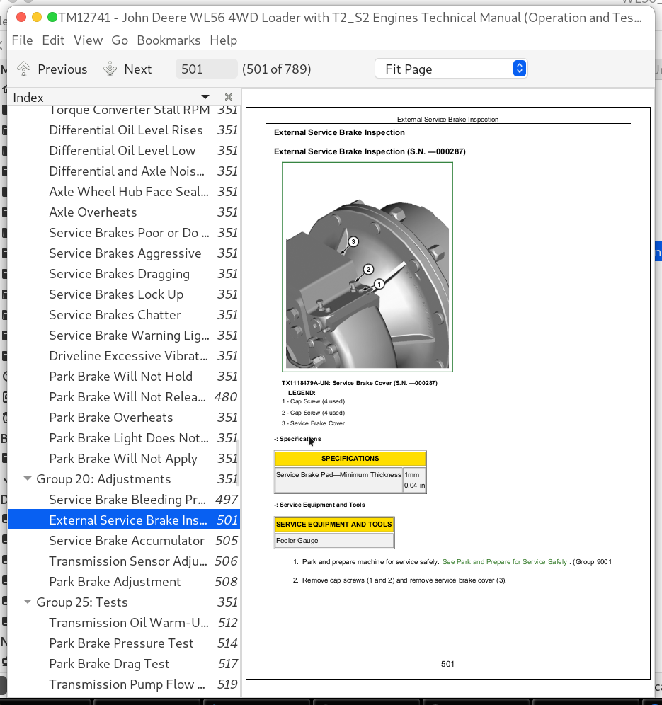
External Service Brake Inspection........501
Service Brake Accumulator........505
Transmission Sensor Adjustment........506
Park Brake Adjustment........508
Group 25: Tests........351
Transmission Oil Warm-Up Procedure........512
Park Brake Pressure Test........514
Park Brake Drag Test........517
Transmission Pump Flow Test........519
Transmission System Pressure Test........521
Transmission Clutch Pressure Test........524
Transmission Element Leakage Test........527
Transmission Lube Pressure Test........530
Torque Converter-In Pressure Test........533
Torque Converter-Out Pressure Test........535
Torque Converter Relief Pressure Test........538
Torque Converter—Out Flow Test........541
Torque Converter Stall Speed Test........544
Transmission Oil Cooler Thermal Bypass Valve Temperature Test........546
Transmission Oil Cooler Thermal Bypass Valve Pressure Test........549
Transmission Oil Cooler Restriction Test........552
Axle Breather Test........555
Section 9025: Hydraulic System........558
Group 05: Theory of Operation........558
Loader Hydraulic System Operation........562
Loader Hydraulic Pump Operation........563
Hydraulic Pump Manifold Operation........565
Steering System Component Operation........570
Steering Valve Operation........571
Pilot Pressure Reducing Valve Operation........573
Service Brake Hydraulic System Operation........574
Service Brake Accumulators Operation........575
Service Brake Valve Operation........577
Pilot Control Lever Operation........579
Loader Control Valve Operation........585
Loader Control Valve With Auxiliary Function Operation—If Equipped........587
Boom Section Operation—Boom Down and Steering........589
Bucket Section Operation........591
Auxiliary Section Operation—If Equipped........593
Main Relief Valve Operation........595
Circuit Relief With Anticavitation Valve Operation........598
Anticavitation Valve Operation........598
Hydraulic Return Filter Operation........599
Group 10: System Diagrams........558
Hydraulic System Schematic........606
Steering Circuit Component Location........610
Loader Circuit Component Location........612
Loader Circuit With Auxiliary Function Component Location—If Equipped........615
Service Brake and Park Brake Component Location........617
Hydraulic Pump Manifold (Hydraulic System Component Location) (S.N. —000261)........620
Hydraulic Pump Manifold (Hydraulic System Component Location) (S.N. 000262—)........622
Group 15: Diagnostic Information........558
No Hydraulic Functions........558
Hydraulic Functions Slow........558
Loader Hydraulic Pump Noisy........559
Loader/Steering Hydraulic Pump Noisy........559
No Steering Function........559
Boom Float Function Not Working........559
One Hydraulic Function Not Working........559
Hydraulic Function Drifts Down........559
Boom Down Does Not Work (Engine Off)........559
Oil Overheats........559
Hydraulic Oil Foams........559
Constant Steering Required to Maintain Straight Travel........559
Slow Steering Wheel Movement Will Not Cause Frame Movement........559
Steering Wheel Turns Without Resistance and Causes No Frame Movement........559
Steering Erratic........559
Steering Wheel Free Play........559
Orbital Steering Valve Binds or Locks Up........559
Steering Wheel Turns By Itself........559
Machine Turns in Opposite Direction as Steering Wheel........559
Steering Wheel Kickback........559
Steering Jerky........559
Group 20: Adjustments........559
Pilot Control Lever Adjustment........676
Accumulator Precharge........678
Group 25: Tests........559
Hydraulic Oil Sampling Procedure........681
Hydraulic Oil Warm-Up Procedure........682
Vacuum Pump Installation........684
Hydraulic System Pressure and Accumulators Discharge........685
JT02156A Digital Pressure and Temperature Analyzer Kit Installation........686
Steering/Loader Hydraulic Pump Flow Test........691
Loader Hydraulic Pump Flow Test........691
Main Relief Valve Pressure Test........695
Circuit Relief With Anticavitation Valve Pressure Test........699
Loader Cylinder Drift Test........703
Boom, Bucket, and Steering Cylinder Leakage Test........706
Hydraulic Oil Cooler Restriction Test........708
Orbital Steering Valve Leakage Test........711
Steering Cylinder Drift Test........715
Pilot Control Valve Pressure Test........719
Pilot Pressure Reducing Valve Pressure Test........725
Pilot Accumulator Gas Precharge Test........728
Cycle Time Test........731
Service Brake Accumulator Gas Precharge and Low Brake Pressure Warning Test........732
Service Brake Valve Pressure Test........735
Service Brake Valve Leakage Test........738
Hydraulic Oil Filter Inspection Procedure........742
Section 9031: Heating and Air Conditioning........743
Group 05: Theory of Operation........743
Air Conditioning System Cycle of Operation........746
Group 10: System Diagrams........743
Air Conditioner and Heater Component Location........749
Group 15: Diagnostic Information........743
Air Conditioning System Does Not Operate........743
Air Conditioner Does Not Cool Interior of Cab........743
Air Conditioning Runs Constantly, Too Cold........743
Heater System Does Not Operate........743
Heater Does Not Warm Interior of Cab........743
Interior Windows Continue to Fog........743
Group 25: Tests........743
Refrigerant Cautions and Proper Handling........774
R134a Refrigerant Cautions........775
R134a Oil Charge Capacity........776
R134a Refrigerant Charge Capacity........777
Refrigerant Hoses and Tubing Inspection........778
R134a Air Conditioning System Test........779
Operating Pressure Diagnostic Chart........782
Air Conditioning High/Low Pressure Switch Test........784
Freeze Control Switch Test........786
Refrigerant Leak Testing........787
John Deere 4WD Loaders WL56 with T2/S2 Engines Operation and Test Service Manual (TM12741)
![]()