
John Deere 744H 4WD Loader & 744H MH Material Handler Repair Service Manual (TM1603)
Complete service repair manual for John Deere 744H 4WD Loader & 744H MH Material Handler, with workshop information to maintain, repair, and service like professional mechanics.
John Deere 744H 4WD Loader & 744H MH Material Handler workshop service repair manual includes:
* Numbered table of contents easy to use so that you can find the information you need fast.
* Detailed sub-steps expand on repair procedure information
* Numbered instructions guide you through every repair procedure step by step.
* Notes, cautions and warnings throughout each chapter pinpoint critical information.
* Bold figure number help you quickly match illustrations with instructions.
* Detailed illustrations, drawings and photos guide you through every procedure.
* Enlarged inset helps you identify and examine parts in detail.
TM1603 - John Deere 744H 4WD Loader and 744H MH Material Handler Technical Manual (Repair).PDF
TM1603 - John Deere 744H 4WD Loader and 744H MH Material Handler Technical Manual (Repair).EPUB
Total Pages: 873 pages
File Format: PDF/EPUB/MOBI/AZW (PC/Mac/Android/Kindle/iPhone/iPad; bookmarked, ToC, Searchable, Printable)
Language: English
MAIN SECTIONS
Foreword
Technical Information Feedback Form
General Information
Safety Information
Wheels
Powered Wheels and Fasteners
Axles and Suspension Systems
Removal and Installation
Axle Shafts and U-Joints
Hydraulic System
Transmission
Transmission, Remove and Install
Gears, Shafts, Bearings and Power Shift Clutch Packs
Hydraulic System
Engine
Removal and Installation
Engine Auxiliary Systems
Cold Weather Starting Aids
Cooling Systems
Speed Controls
Intake System
External Exhaust System
External Fuel Supply Systems
Flex Plate Drive
Elements
Steering System
Hydraulic System
Service Brakes
Active Elements
Hydraulic System
Park Brake
Active Elements
Hydraulic System
Electrical Systems
Batteries, Support and Cables
Alternator, Regulator and Charging System Wiring
Lighting System
Wiring Harness and Switches
System Controls
Frame or Supporting Structure
Frame Installation
Frame Bottom Guards
Chassis Weights
Operator’s Station
Removal and Installation
Operator Enclosure
Seat and Seat Belts
Heating and Air Conditioning
Sheet Metal and Styling
Hood or Engine Enclosure
Miscellaneous Shields
Grille and Grille Housing
Safety and Convenience
Mirror
Fire Extinguisher
Horn and Warning Devices
Loader
Bucket
Frames
Hydraulic System
Dealer Fabricated Tools
tm1603 - 744H Loader and 744H MH Material Handler
Table of Contents
Foreword
Technical Information Feedback Form
Section 00: General Information
Group 0001: Safety Information
Recognize Safety Information
Follow Safety Instructions
Operate Only If Qualified
Wear Protective Equipment
Avoid Unauthorized Machine Modifications
Add Cab Guarding For Special Uses
Inspect Machine
Stay Clear Of Moving Parts
Avoid High-Pressure Fluids
Beware Of Exhaust Fumes
Prevent Fires
Prevent Battery Explosions
Handle Chemical Products Safely
Dispose of Waste Properly
Prepare for Emergencies
Use Steps And Handholds Correctly
Start Only From Operator's Seat
Use And Maintain Seat Belt
Prevent Unintended Machine Movement
Avoid Work Site Hazards
Use Special Care When Operating Loader
Keep Riders Off Machine
Avoid Backover Accidents
Avoid Machine Tip Over
Operating on Slopes
Operating Or Traveling On Public Roads
Inspect and Maintain ROPS
Add And Operate Attachments Safely
Park And Prepare For Service Safely
Service Cooling System Safely
Remove Paint Before Welding or Heating
Make Welding Repairs Safely
Drive Metal Pins Safely
Group 0003: Torque Values
Metric Bolt and Cap Screw Torque Values
Additional Metric Cap Screw Torque Values
Unified Inch Bolt and Cap Screw Torque Values
Service Recommendations for 37° Flare and 30° Cone Seat Connectors
Service Recommendations for O-Ring Boss Fittings
O-Ring Boss Fittings in Aluminum Housing Service Recommendations—Excavators
Service Recommendations for Flared Connections—Straight or Tapered Threads
Service Recommendations for Flat Face O-Ring Seal Fittings
O-Ring Face Seal Fittings With SAE Inch Hex Nut and Stud End for High-Pressure Service Recommendations
O-Ring Face Seal Fittings With Metric Hex Nut and Stud End for Standard Pressure Service Recommendations
O-Ring Face Seal Fittings With Metric Hex Nut and Stud End for High-Pressure Service Recommendations
Service Recommendations for Metric Series Four Bolt Flange Fitting
Service Recommendations For Inch Series Four Bolt Flange Fittings
Inch Series Four Bolt Flange Fitting for High-Pressure Service Recommendations
Service Recommendations For Non-Restricted Banjo (Adjustable) Fittings
Service Recommendations For O-Ring Boss Fittings With Shoulder
Metric 24° O-Ring Seal DIN 20078 Service Recommendations
Section 01: Wheels
Group 0110: Powered Wheels and Fasteners
Service Equipment and Tools
Specifications
Remove and Install Wheel
Remove Tire
Install Tire
Section 02: Axles and Suspension Systems
Group 0200: Removal and Installation
John Deere 1600 Series Axles—Use CTM138719
Service Equipment and Tools
Specifications
Remove and Install Front Axle and Differential
Remove Rear Axle and Differential
Install Rear Axle and Differential
Group 0225: Axle Shafts and U-Joints
Specifications
Remove and Install Front, Articulation and Rear Drive Shafts
Disassemble, Inspect, and Assemble Front, Articulation and Rear Drive Shafts
Group 0260: Hydraulic System
Specifications
Remove and Install Differential Lock Solenoid Valve
Remove and Install Pin Disconnect/Axle Disconnect Valve
Disassemble and Assemble Pin Disconnect Valve
Section 03: Transmission
Group 0300: Transmission, Remove and Install
Essential Tools
Service Equipment and Tools
Specifications
Remove and Install Transmission
Group 0350: Gears, Shafts, Bearings and Power Shift Clutch Packs
Essential Tools
Service Equipment and Tools
Other Material
Specifications
Remove and Install Torque Converter
Disassemble Torque Converter Housing
Remove and Install Transmission Power Take-Off (If Equipped)
Disassemble and Assemble Transmission Power Take-Off (If Equipped)
Assemble Torque Converter Housing
Remove Final Drive
Install Final Drive
Remove Clutch Packs
Disassemble 3rd Speed Clutch (K3)/Hi Range Forward Clutch (K4)
Assemble 3rd Speed Clutch (K3)/Hi Range Forward Clutch (K4)
Disassemble Reverse Clutch(KR)/2nd Speed Clutch (K2)
Assemble Reverse Clutch (KR)/2nd Speed Clutch (K2)
Disassemble Low Range Forward Clutch (KV)/1st Speed Clutch (K1)
Assemble Low Range Forward Clutch (KV)/1st Speed Clutch (K1)
Adjust Transmission Speed Sensor
Group 0360: Hydraulic System
Essential Tools
Other Material
Specifications
Remove and Install Transmission Oil Pump
Disassemble and Assemble Transmission Oil Pump
Disassemble Delivery Lines and Channel Plate
Install Breather, Channel Plate and Shift Control
Hydraulic Control Unit—Exploded View
Disassemble Hydraulic Control Unit
Assemble Hydraulic Control Unit
Install Transmission Filter
Section 04: Engine
Group 0400: Removal and Installation
John Deere Engine Repair—Use CTM100
Essential Tools
Service Equipment and Tools
Specifications
Other Material
Remove and Install Engine (S.N. —581927)
Remove and Install Engine (S.N. 581928— )
Remove and Install Oil Pan
Section 05: Engine Auxiliary Systems
Group 0505: Cold Weather Starting Aids
Other Material
Remove and Install Starting Aid Nozzle
Group 0510: Cooling Systems
Other Material
Specifications
Inspect Serpentine Belts (S.N. —581927)
Inspect Serpentine Belts (S.N. 581928— )
Remove and Install Serpentine Belts (S.N. —581927)
Remove and Install Serpentine Belts (S.N. 581928— )
Check and Adjust Air Conditioning Compressor Belt Tension—If Equipped
Belt Tensioner Spring Check
Remove and Install Fan and Fan Drive (S.N. —581927)
Remove and Install Fan and Fan Drive (S.N. 581928— )
Remove and Install Radiator (S.N. —581927)
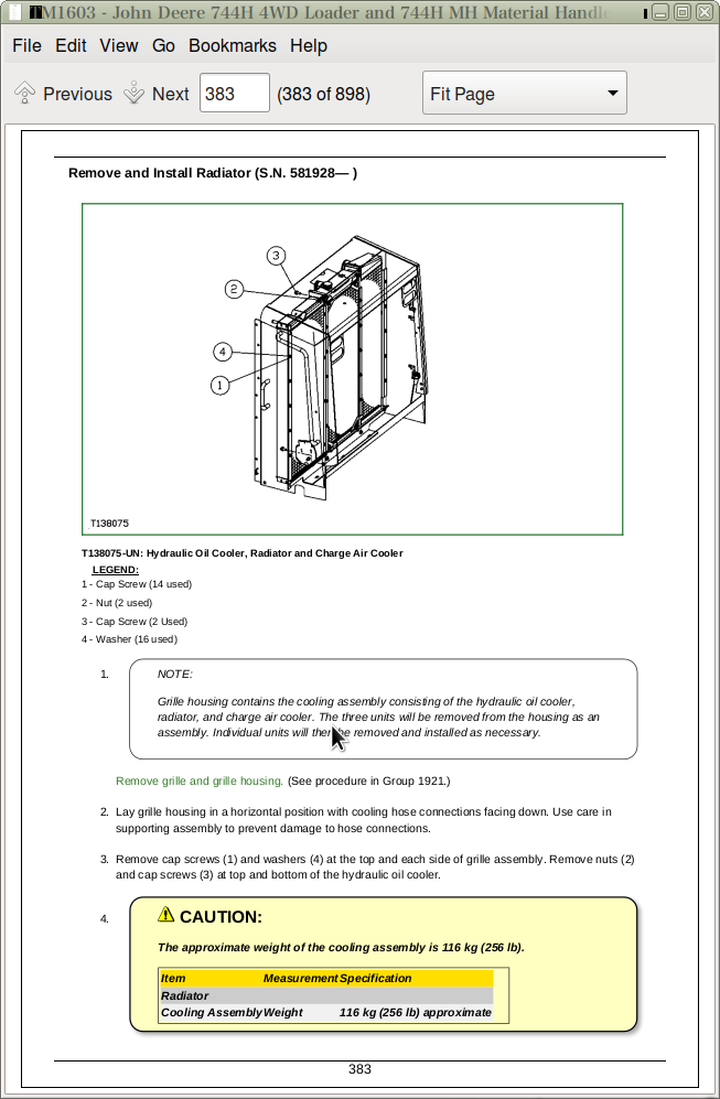
Remove and Install Radiator (S.N. 581928— )
Remove and Install Hydraulic Oil Cooler (S.N. —581927)
Remove and Install Oil Cooler (S.N. 581928— )
Remove and Install Coolant Level Sensor (S.N. —581927)
Cooling System Fill and Deaeration Procedure (S.N. 581928— )
Group 0515: Speed Controls
Remove and Install Speed Control Linkage (S.N. —581927)
Remove and Install Speed Control Linkage (S.N. 581928— )
Analog Throttle Position Sensor Adjustment
Group 0520: Intake System
Service Equipment and Tools
Specifications
Tighten Air Cleaner Hose Clamps
Remove and Install Air Filter Elements
Air Intake System Leakage Test
Remove and Install Charge Air Cooler (S.N. 581928— )
Group 0530: External Exhaust System
Remove and Install Muffler (S.N. —581927)
Remove and Install Muffler (S.N. 581928—)
Group 0560: External Fuel Supply Systems
Specifications
Remove and Install Fuel Tank (S.N. —581927)
Remove and Install Fuel Tank (S.N. 581928— )
Section 07: Flex Plate Drive
Group 0752: Elements
Specifications
Remove and Install Flex Plate
Section 09: Steering System
Group 0960: Hydraulic System
Service Equipment and Tools
Other Material
Specifications
Remove and Install Steering Valve
Remove and Install Steering Column
Remove and Install Steering Cylinders
Disassemble Steering Cylinders
Steering Cylinder—Cross Section
Assemble Steering Cylinder
Remove and Install Steering Cylinder Bushings
Remove and Install Priority Valve
Disassemble and Assemble Priority Valve
Section 10: Service Brakes
Group 1011: Active Elements
Brake Element Repair for 1600 Series John Deere Axle—Use CTM138719
Specifications
Inspect Service Brake Pads
Remove and Install Brake Assembly
Brake Linkage Adjustment
Group 1060: Hydraulic System
Specifications
Remove and Install Brake Valve
Remove and Install Brake Accumulator
Hydraulic Brake Bleeding Procedure
Remove and Install Pressure Reducing Valve Manifold
Section 11: Park Brake
Group 1111: Active Elements
Service Equipment and Tools
Other Material
Specifications
Remove and Install Driveline Bearing Park Brake
Disassemble and Assemble Driveline Bearing Park Brake
Group 1160: Hydraulic System
Specifications
Remove and Install Driveline Bearing Park Brake Release Solenoid Valve
Remove and Install Driveline Bearing Park Brake Pressure Switch
Section 16: Electrical Systems
Group 1671: Batteries, Support and Cables
Service Batteries Carefully
Check Battery Electrolyte Level and Terminals
Battery Charging Procedure
Using Booster Batteries—24 Volt System
Procedure for Testing Batteries
Remove and Install Batteries (S.N. —581927)
Remove and Install Batteries (S.N. 581928— )
Remove and Install Manual Battery Disconnect Switch
Group 1672: Alternator, Regulator and Charging System Wiring
Alternators and Starter Motors—Use CTM77
Remove and Install Alternator
Remove and Install Regulator
Group 1673: Lighting System
Replace Halogen Bulbs
Remove and Install Work Lights
Remove and Install Turn, Tail, and Brake Lights (S.N. —581927)
Remove and Install Turn, Tail, and Brake Lights (S.N. 581928—)
Cab Work Lights Harness
Group 1674: Wiring Harness and Switches
Essential Tools
Service Equipment and Tools
Other Material
Specifications
Fuse (Blade-Type) Color Codes
Fuse Specifications (S.N. —581927)
Fuse Specifications (S.N. 581928—)
Remove and Install Pressure Switches
Boom Height Kickout Adjustment
Return-To-Carry Kickout Adjustment
Return-to-Dig Adjustment (S.N. —564434)
Return-To-Dig Adjustment (S.N. 564435— )
Replace METRI-PACK Metri-Pack is a trademark of Packard Electrical. Connectors
Install METRI-PACK Metri-Pack is a trademark of Packard Electric. Contact
Replace DEUTSCH DEUTSCH is a trademark of the Deutsch Co. Connectors
Install DEUTSCH DEUTSCH is a trademark of the Deutsch Co. Contact
Replace WEATHER PACK WEATHER PACK is a trademark of Packard Electric. Connector
Install WEATHER PACK WEATHER PACK is a trademark of Packard Electric. Contact
Replace CINCH CINCH is a trademark of the Cinch Co. Connectors
Install CINCH CINCH is a trademark of the Cinch Co. Contact
Remove Connector Body from Blade Terminals
Remove Blade Terminals From Fuse Block
Group 1675: System Controls
Remove and Install Transmission Controller
Remove and Install Engine Controller
Remove and Install Chassis Computer Unit
Remove and Install Monitor Display Unit
Reprogram Monitor Display Unit
Monitor Display Unit Menus
Section 17: Frame or Supporting Structure
Group 1740: Frame Installation
Service Equipment and Tools
Specifications
Welding Repair of Major Structure
Separate Engine and Loader Frame
Upper Pivot Bearing and Seals Remove and Install
Lower Pivot Bearing and Seals Remove and Install
Group 1746: Frame Bottom Guards
Specifications
Remove and Install Guards
Group 1749: Chassis Weights
Specifications
Remove and Install Counterweights (S.N. —581927)
Section 18: Operator’s Station
Group 1800: Removal and Installation
Essential Tools
Service Equipment and Tools
Specifications
Remove and Install Cab
Tilt Cab
Group 1810: Operator Enclosure
Other Material
Specifications
Remove and Install Windowpanes
Remove and Install Windshield Washer
Remove and Install Front and Rear Windshield Wiper Motor
Adjust Front Windshield Wiper
Remove and Install Wrist Support (S.N. —581927)
Group 1821: Seat and Seat Belts
Disassemble and Assemble Seat Belt
Disassemble and Assemble Seat
Group 1830: Heating and Air Conditioning
Essential Tools
Air Conditioning System Fittings Reference Chart
Other Material
Specifications
R134a Refrigerant Cautions
R134a Compressor Oil Charge Check
R134a Compressor Oil Removal
R134a Component Oil Charge
Leak Testing
Refrigerant Hoses and Tubing Inspection
R134a Refrigerant, Recovery, Recycling and Charging Station Installation Procedure
Recover R134a System
Evacuate R134a System
Charge R134a System
Air Conditioner System Cleaning Procedures
Purge Air Conditioner System
Flush Air Conditioner System
Air Conditioning Module With Heater/Evaporator Core
Remove and Install Heater/Evaporator Core
Expansion Valve Remove and Install
Remove and Install Freeze Control Switch
Bench Test A/C Thermostat Control Switch
Remove and Install Heater Control Valve
Heater Control Valve Leak Check
Remove and Install Main Blower Assembly
Remove and Install Pressurizer Motor Assembly
Remove and Install Receiver-Dryer and Condenser (S.N. —581927)
Remove and Install Receiver-Dryer and Condenser (S.N. 581928—)
Remove and Install High and Low Pressure Switches
Remove and Install Recirculating Air Filter
Remove and Install Fresh Air Filter
Remove and Install Compressor (S.N. —581927)
Remove and Install Compressor (S.N. 581928—)
Check and Adjust Compressor Belt Tension (S.N. —581927)
Belt Tensioner Spring Check (S.N. 581928— )
Disassemble and Inspect Compressor
Assemble Compressor
Inspect Compressor Manifolds
Section 19: Sheet Metal and Styling
Group 1910: Hood or Engine Enclosure
Specifications
Remove and Install Hood (S.N. —581927)
Remove and Install Hood (S.N. 581928— )
Remove and Install Engine Side Shields (S.N. —581927)
Remove and Install Engine Side Shields (S.N. 581928— )
Group 1913: Miscellaneous Shields
Remove and Install Transmission Shields
Remove and Install Battery Covers (S.N. —581927)
Remove and Install Battery Covers (S.N. 581928—)
Group 1921: Grille and Grille Housing
Essential Tools
Service Equipment and Tools
Specifications
Remove and Install Grille and Grille Housing (S.N. —581927)
Remove and Install
Section 20: Safety and Convenience
Group 2002: Mirror
Remove and Install Rear View Mirror
Remove and Install Outside Mirror for Cab or Canopy
Group 2003: Fire Extinguisher
Remove and Install Fire Extinguisher and Bracket
Group 2004: Horn and Warning Devices
Remove and Install Horn
Remove and Install Reverse Warning Alarm (S.N. —581927)
Remove and Install Reverse Warning Alarm (S.N. 581928—)
Change Reverse Warning Alarm Volume (S.N. —581927)
Change Reverse Warning Alarm Volume (S.N. 581928—)
Section 31: Loader
Group 3102: Bucket
Service Equipment and Tools
Specifications
Ride Control Accumulator Safety
Remove and Install Bucket Tooth Shanks and Tips
Remove and Install Bucket
Remove and Install Welded Bucket Cutting Edges
Remove and Install Wear Plate Bucket Cutting Edges
Repair Cracked Cutting Edge
Group 3140: Frames
Service Equipment and Tools
Other Material
Specifications
Remove and Install Bucket Tilt Linkage
Remove and Install Bucket Linkage Seals and Bushings
Remove and Install Boom
Remove and Install Boom Bushings, Seals and Shims
Group 3160: Hydraulic System
Essential Tools
Service Equipment and Tools
Other Material
Specifications
Remove and Install Steering/Loader Hydraulic Pump
Remove and Install Loader Hydraulic Pump
Steering/Loader Hydraulic Pump (PVG 75)—Cross Section
Disassemble, Inspect and Assemble Steering/Loader Hydraulic Pump and Loader Hydraulic Pump
Remove and Install Hydraulic Pump Control Valve
Disassemble and Assemble Hydraulic Pump Control Valve
Remove and Install Loader Control Valve
Disassemble and Assemble Loader Control Valve
Disassemble and Assemble Auxiliary Valve Section and Bucket Valve Section
Disassemble and Assemble Boom Valve Section
Disassemble and Assemble System Relief Valve
Disassemble and Assemble Anti-Cavitation Valve
Service Bucket and Boom Section Pilot Orifice Check Valve
Remove and Install Boom Cylinder
Remove and Install Bucket Cylinder
Disassemble Boom or Bucket Cylinder
Assemble Boom or Bucket Cylinder
Remove and Install Boom or Bucket Cylinder Bushings and Seals
Loader Start-Up Procedure
Remove and Install Hydraulic Oil Reservoir
Hydraulic Oil Clean-Up Procedure Using Portable Filter Caddy
Remove and Install Pilot Controller Valve (Single Lever Controller)
Cross Section of Pilot Controller Valve (Single Lever Controller)
Disassemble and Assemble Pilot Controller Valve (Single Lever Controller)
Remove and Install Pilot Controller Valve (Two Lever Controller)
Disassemble and Assemble Pilot Controller Valve (Two Lever Controller)
Remove and Install Pressure Reducing Valve
Remove and Install Boom Down Solenoid Valve
Ride Control Valve Remove and Install
Ride Control Valve Disassemble and Assemble
Ride Control Accumulator Remove and Install
Section 99: Dealer Fabricated Tools
Group 9900: Dealer Fabricated Tools
DFT1091 Cylinder Stand Shim
DF1044 Air Deflector Bushing
John Deere 744H 4WD Loader & 744H MH Material Handler Repair Service Manual (TM1603)
![]()