
John Deere 4WD Loaders Model 644K Hybrid Operation and Test Service Manual (TM12707)

Complete Diagnosis and Test Service manual with electrical wiring diagrams for John Deere 4WD Loaders Model 644K Hybrid (iT4/S3B) (SN. from E651322)(PIN: 1DW644K Hybrid***E651322-), with all the shop information to maintain, diagnose, and rebuild like professional mechanics.
John Deere 4WD Loaders Model 644K Hybrid workshop Operation and Test Service manual includes:
* Numbered table of contents easy to use so that you can find the information you need fast.
* Detailed sub-steps expand on repair procedure information
* Numbered instructions guide you through every repair procedure step by step.
* Troubleshooting and electrical service procedures are combined with detailed wiring diagrams for ease of use.
* Notes, cautions and warnings throughout each chapter pinpoint critical information.
* Bold figure number help you quickly match illustrations with instructions.
* Detailed illustrations, drawings and photos guide you through every procedure.
* Enlarged inset helps you identify and examine parts in detail.
TM12707 - John Deere 4WD Loaders Model 644K Hybrid Technical Manual - Operation and Test.PDF
TM12707 - John Deere 4WD Loaders Model 644K Hybrid Technical Manual - Operation and Test.epub
Total Pages: 3,112 pages
File Format: PDF/EPUB/MOBI/AZW (PC/Mac/Android/Kindle/iPhone/iPad; bookmarked, ToC, Searchable, Printable)
Language: English
MAIN SECTIONS
Foreword
Manual Identification-READ THIS FIRST!
General Information
Safety Information
Diagnostic Trouble Codes (DTCs)
Engine Control Unit (ECU) Diagnostic Trouble Codes
Transmission Control Unit (TCU) Diagnostic Trouble Codes
Vehicle Control Unit (VCU) Diagnostic Trouble Codes
Sealed Switch Module (SSM) Diagnostic Trouble Codes
Advanced Display Unit (ADU) Diagnostic Trouble Codes
Rear Object Detection (ROD) Diagnostic Trouble Codes
Ground Speed Radar (RDR) Diagnostic Trouble Codes
Joystick Steering Valve (JSV) Diagnostic Trouble Codes
Joystick Steering Controller (JSC) Diagnostic Trouble Codes
Tire Pressure Monitoring (TPM) System Diagnostic Trouble Codes
Motor Inverter (MT1) Diagnostic Trouble Codes
Generator Inverter (GN1) Diagnostic Trouble Codes
Operational Checkout Procedure
Operational Checkout Procedure
Engine
Theory of Operation
System Diagrams
Diagnostic Information
Adjustments
Tests
Electrical System
Theory of Operation
System Diagrams
Diagnostic Information
Monitor Operation
Adjustments
Tests
Electric Drive System
Theory of Operation
System Diagrams
Tests
Power Train
Theory of Operation
System Diagrams
Diagnostic Information
Adjustments
Tests
Hydraulic System
Theory of Operation
System Diagrams
Diagnostic Information
Adjustments
Test
Heating and Air Conditioning
Theory of Operation
System Diagrams
Diagnostic Information
Tests
tm12707 - 644K Hybrid 4WD Loader
Table of Contents
Foreword
Manual Identification—READ THIS FIRST!
Section 9000: General Information
Group 0001: Safety Information
Recognize Safety Information
Follow Safety Instructions
Operate Only If Qualified
Wear Protective Equipment
Avoid Unauthorized Machine Modifications
Inspect Machine
Stay Clear of Moving Parts
Avoid High-Pressure Fluids
Avoid High-Pressure Oils
Work In Ventilated Area
Prevent Fires
Clean Debris from Machine
Prevent Battery Explosions
Handle Chemical Products Safely
Decommissioning — Proper Recycling and Disposal of Fluids and Components
Exhaust Filter Ash Handling and Disposal
Prepare for Emergencies
Add Cab Guarding for Special Uses
Use Steps and Handholds Correctly
Start Only From Operator's Seat
Use and Maintain Seat Belt
Prevent Unintended Machine Movement
Avoid Work Site Hazards
Use Special Care When Operating Loader
Keep Riders Off Machine
Avoid Backover Accidents
Avoid Machine Tip Over
Operating on Slopes
Operating or Traveling On Public Roads
Inspect and Maintain ROPS
Add and Operate Attachments Safely
High-Altitude Operation
Park and Prepare for Service Safely
Prepare Electric Drive System for Service Safely
Avoid Pressure Washing Electric Drive Components
Clean Exhaust Filter Safely
Service Cooling System Safely
Service Tires Safely
Remove Paint Before Welding or Heating
Make Welding Repairs Safely
Drive Metal Pins Safely
Section 9001: Diagnostic Trouble Codes (DTCs)
Group 10: Engine Control Unit (ECU) Diagnostic Trouble Codes
Engine Control Unit (ECU) Diagnostic Trouble Codes
000111.07 - Engine Coolant Out of Range
000237.31 - Invalid VIN
001321.05 - Starter Relay Open Circuit
001321.06 - Starter Relay High Current
001321.09 - Starter Signal Invalid
001321.16 - Too Long to Start
001321.31 - Starter Sol Open Circuit
002003.09 - CAN Comm Lost For TCU
003353.31 - Alternator Excitation Condition Exists
Group 20: Transmission Control Unit (TCU) Diagnostic Trouble Codes
Transmission Control Unit (TCU) Diagnostic Trouble Codes
000158.03 - Switched Power Voltage High
000158.04 - Switched Power Voltage Low
000168.03 - High Battery Voltage
000168.04 - Low Battery Voltage
000177.00 - Trans Oil Temp Overtemp
000177.04 - Trans Oil Temp Short To Gnd
000177.15 - Trans Oil Temp High Temp
000177.16 - Trans Oil Temp High Temp
000190.00 - Engine Speed Too High
000234.02 - Invalid TCU Software Rev
000237.31 - Invalid VIN
000521.03 - Brake Pedal Short to Power
000521.04 - Brake Pedal Open Circuit or Short to Ground
000544.02 - Ref Torque Invalid
000751.12 - Range Select Error
000628.12 - Controller Not Programmed
000880.05 - Brake Lights Open or Short
000880.06 - Brake Lights High Current
000880.18 - Brake Lights Lamp Failure
002000.09 - CAN Comm Lost For ECU
002033.09 - CAN Comm Lost for VCU
002139.09 - CAN Comm Lost For WP1
002160.09 - CAN Comm Lost For GN1
002162.09 - CAN Comm Lost For MT1
003509.04 - Sensor Supply 1 Voltage Low
003510.04 - Sensor Supply 2 Voltage Low
003511.04 - Sensor Supply 3 Voltage Low
003655.04 - JS Shift Up Short to Gnd
003656.04 - JS Shift Down Short to Gnd
520351.00 - GN1 IGBT Temp Overtemp
520351.15 - GN1 IGBT High Temp
520351.16 - GN1 IGBT High Temp
520505.00 - Motor Speed Too High
520536.04 - Park Brake Sw Short to Gnd
520537.04 - Quick Shift Short to Gnd
520539.04 - Col FNR-R Short to Gnd
520540.04 - Col FNR-F Short to Gnd
520552.04 - 2nd FNR-R Short to Gnd
520553.04 - 2nd FNR-F Short to Gnd
520555.03 - Accel Pedal Short to Power
520555.04 - Accel Pedal Short to Ground
521041.00 - GN1 Winding Overtemp
521041.15 - GN1 Winding Temp High Temp
521041.16 - GN1 Winding Temp High Temp
521043.00 - Brake Res Temp Overtemp
521043.15 - Brake Res Temp High Temp
521043.16 - Brake Res Temp High Temp
521601.02 - EOL Config Invalid
521839.01 - DC Bus A Isolation Loss
521839.18 - DC Bus A Isolation Loss
521932.00 - MT1 IGBT Temp Overtemp
521932.15 - MT1 IGBT Temp High Temp
521932.16 - MT1 IGBT Temp High Temp
522000.02 - Invalid MT1 Software Rev
522003.04 - 2nd FNR-NR Short to Gnd
522190.04 - Col Range-B3 Short to Gnd
522191.04 - Col Range-B2 Short to Gnd
522192.04 - Col Range-B1 Short to Gnd
522252.02 - CL1 Hold Time Invalid
522252.16 - CL1 Hold Time Excessive
522252.18 - CL1 Hold Time Too Low
522253.02 - CL2 Hold Time Invalid
522253.16 - CL2 Hold Time Excessive
522253.18 - CL2 Hold Time Too Low
522254.02 - CL3 Hold Time Invalid
522254.16 - CL3 Hold Time Excessive
522254.18 - CL3 Hold Time Too Low
522327.00 - MT1 Winding Temp Overtemp
522327.15 - MT1 Winding Temp High Temp
522327.16 - MT1 Winding Temp High Temp
522364.00 - Clutch Cal High Speed
522364.01 - Clutch Cal Low Speed
522364.13 - Clutch Cal Required
522365.13 - Limp Home Mode
522366.13 - Application Invalid
522367.13 - TCU Config Invalid
522373.03 - Power Supply High Voltage
522373.04 - Power Supply Low Voltage
522375.00 - Transmission Oil Filter Restricted
522379.02 - Park Brake Sol Failure
522379.05 - Park Brake Sol Open to Short
522379.06 - Park Brake Sol Short to Gnd
522382.02 - Backup Alarm Failure
522382.05 - Backup Alarm Open or Short
522382.06 - Backup Alarm High Current
522392.02 - Clutch 3 Slippage
522392.03 - Clutch 3 Sol Short to Power
522392.04 - Clutch 3 Sol Short to Gnd
522392.10 - Clutch 3 Slippage
522392.12 - Clutch 3 Fault
522395.02 - Clutch 2 Slippage
522395.03 - Clutch 2 Sol Short to Power
522395.04 - Clutch 2 Sol Short to Gnd
522395.10 - Clutch 2 Slippage
522395.12 - Clutch 2 Fault
522399.02 - Clutch 1 Slippage
522399.03 - Clutch 1 Sol Short to Power
522399.04 - Clutch 1 Sol Short to Gnd
522399.10 - Clutch 1 Slippage
522399.12 - Clutch 1 Fault
522401.15 - Output Shaft Overspeed
522409.04 - 2nd FNR-NF Short to Gnd
522409.05 - 2nd FNR Open Circuit
522409.12 - 2nd FNR Mult Inputs
522411.04 - Col FNR-N Short to Gnd
522411.05 - Col FNR Open Circuit
522411.12 - Col FNR Mult Inputs
522769.31 - Generator Harness Connector Fault
522770.31 - Motor Harness Connector Fault
523380.31 - Drivetrain Derate Active
523652.31 - Harness Shielding Fault
523725.02 - CL3 Fill Time Invalid
523725.16 - CL3 Fill Time Excessive
523725.18 - CL3 Fill Time Too Low
523726.02 - CL2 Fill Time Invalid
523726.16 - CL2 Fill Time Excessive
523726.18 - CL2 Fill Time Too Low
523727.02 - CL1 Fill Time Invalid
523727.16 - CL1 Fill Time Excessive
523727.18 - CL1 Fill Time Too Low
523821.02 - Invalid GN1 Software Rev
523910.02 - Data Memory Failure
523996.03 - GN1 & Engine Speed Not in Sync
524039.00 - Generator Speed Too High
524055.11 - NV Memory Fault
524099.02 - WP1 Operation Fault
524099.07 - WP1 Cavitation
524099.18 - WP1 Coolant Low
524265.19 - Checksum Error
524282.00 - Engage Gear High Speed
Group 30: Vehicle Control Unit (VCU) Diagnostic Trouble Codes
Vehicle Control Unit (VCU) Diagnostic Trouble Codes
000075.00 - Front Axle Oil High Temp
000075.04 - Front Axle Oil Temp Sensor Short to Ground
000096.04 - Fuel Level Short to Ground
000096.05 - Fuel Level Open or Short
000167.16 - Alternator High Voltage
000167.18 - Alternator Low Voltage
000168.16 - High Battery Voltage
000171.04 - Ambient Air Short to Ground
000237.31 - Invalid VIN
000444.05 - 12 V Center Tap Open or Short
000444.18 - Battery Voltage Imbalance
000578.00 - Rear Axle Oil High Temp
000578.04 - Rear Axle Oil Temp Sensor Short to Ground
000628.12 - Controller Not Programmed
000629.12 - VCU Watchdog Time Out
000639.12 - VCU CAN 1 Failure
000639.14 - VCU CAN 1 Bus Off
000746.03 - Diff Lock Sol Short to Power
000746.05 - Diff Lock Sol Open Circuit
000746.06 - Diff Lock Sol High Current
000785.03 - Pilot Solenoid Short to Power
000785.05 - Pilot Solenoid Open Circuit
000785.06 - Pilot Solenoid High Current
000977.03 - Rev Fan Sol Short to Power
000977.05 - Rev Fan Sol Open Circuit
000977.06 - Rev Fan Sol High Current
001071.03 - Fan Solenoid (HS) Short to Power
001071.05 - Fan Solenoid (HS) Open Circuit
001071.06 - Fan Solenoid (HS) High Current
001071.13 - Fan Solenoid Out of Calibration
001071.16 - Fan Solenoid (LS) High Current
001071.17 - Fan Solenoid (LS) Open Circuit
001071.18 - Proportional Fan Solenoid Low Side (LS) Short to Power
001231.12 - VCU CAN 2 Failure
001231.14 - VCU CAN 2 Bus Off
001503.04 - Arm Rest Dn Short to Ground
001503.11 - Arm Rest Position Undetermined
001550.03 - AC Clutch Short to Power
001550.06 - AC Clutch High Current
001565.04 - Arm Rest Up Switch Short to Ground
001638.00 - Hydraulic Oil High Temp
001638.04 - Hydraulic Oil Temp Short to Ground
001639.02 - Fan Speed Sensor Out of Sync
001639.04 - Fan Speed Sensor Short to Ground
001639.05 - Fan Speed Sensor Open Circuit
001639.08 - Fan Speed Sensor No Signal
001639.10 - Fan Speed Sensor Fault
001639.13 - Fan Speed Sensor Out of Calibration
001713.01 - Hydraulic Oil Filter Restricted
002000.09 - CAN Comm Lost For ECU
002003.09 - CAN Comm Lost for TCU
002040.09 - CAN Comm Lost for ADU
002051.09 - CAN Comm Lost for TPMS
002052.09 - CAN Comm Lost for JSC
002129.09 - CAN Comm Lost for JSV
002132.09 - CAN Comm Lost for ROD
002141.09 - CAN Comm Lost for SSM
002169.09 - CAN Comm Lost for RDR
002251.09 - Controller Area Network (CAN) Lost for JDLink™
002350.03 - Drive Lamps Short to Power
002350.05 - Drive Lamps Open Circuit
002350.06 - Drive Lamps High Current
002355.03 - Front Work Lts Short to Power
002355.05 - Front Work Lts Open Circuit
002355.06 - Front Work Lts High Current
002356.03 - Front Work Lts Short to Power
002356.05 - Front Work Lts Open Circuit
002356.06 - Front Work Lts High Current
002362.03 - Rear Work Lts Short to Power
002362.05 - Rear Work Lts Open Circuit
002362.06 - Rear Work Lts High Current
002367.04 - Left Turn Sw Short to Ground
002368.03 - Left Turn Lts Short to Power
002368.05 - Left Turn Lts Open Circuit
002368.06 - Left Turn Lts High Current
002369.04 - Right Turn Sw Short to Ground
002370.03 - Right Turn Lts Short to Power
002370.05 - Right Turn Lts Open Circuit
002370.06 - Right Turn Lights High Current
002378.05 - Marker/Tail Lights Open Circuit
002378.06 - Marker/Tail Lights High Current
002386.03 - Beacon Light Short to Power
002386.06 - Beacon Light High Current
002680.03 - RTC/Float Detent Short to Power
002680.05 - RTC/Float Detent Open Circuit
002680.06 - RTC/Float Detent High Current
002697.02 - Timeout JSC Message
002717.03 - RTD Detent Short to Power
002717.05 - RTD Detent Open or Short
002717.06 - RTD Detent High Current
002754.03 - BHKO Detent Short to Power
002754.05 - BHKO Detent Open Circuit
002754.06 - BHKO Detent High Current
002873.04 - Engine Light Sw Short to Ground
002873.18 - Engine Light Sw Short to Ground
002875.04 - Hazard Wakeup Short to Ground
003509.04 - Sensor Supply 1 Voltage Low
003510.04 - Sensor Supply 2 Voltage Low
003511.04 - Sensor Supply 3 Voltage Low
003598.02 - 7 V Supply Voltage Low
521948.02 - Engine Tier Level Invalid
521985.04 - CPU Switched Power Voltage Low
521986.04 - Unswitched Power Voltage Low
522341.03 - Heated Mirror Short to Power
522341.05 - Heated Mirror Open Circuit
522341.06 - Heated Mirror High Current
522426.04 - Rear Wiper Park Short to Ground
522427.04 - Front Wiper Park Short to Ground
522431.02 - Memory Test Malfunction
522432.03 - R Wiper Hi-Spd Short to Power
522432.05 - R Wiper Hi-Spd Open Circuit
522432.06 - R Wiper Hi-Spd High Current
522433.03 - R Wiper Lo-Spd Short to Power
522433.05 - R Wiper Lo-Spd Open Circuit
522433.06 - R Wiper Lo-Spd High Current
522434.03 - F Wiper Lo-Spd Short to Power
522434.05 - F Wiper Lo-Spd Open Circuit
522434.06 - F Wiper Lo-Spd High Current
522435.03 - F Wiper Hi-Spd Short to Power
522435.05 - F Wiper Hi-Spd Open Circuit
522435.06 - F Wiper Hi-Spd High Current
522436.03 - Bucket Pos Short to Power
522436.04 - Bucket Pos Open or Short
522437.04 - RTDig Switch 1 Short to Ground
522438.03 - Pin Disc Sol Short to Power
522438.05 - Pin Disc Sol Open Circuit
522438.06 - Pin Disc Sol High Current
522543.03 - Boom Cyl Rod Press Open or Short
522543.04 - Boom Cyl Rod Press Short to Ground
522544.03 - Boom Cyl Head Press Open or Short
522544.04 - Boom Cyl Head Press Short to Ground
522620.03 - Vehicle Horn Short to Power
522620.06 - Vehicle Horn High Current
522796.03 - R Washer Pump Short to Power
522796.05 - R Washer Pump Open Circuit
522796.06 - R Washer Pump High Current
522797.03 - F Washer Pump Short to Power
522797.05 - F Washer Pump Open Circuit
522797.06 - F Washer Pump High Current
523219.04 - Switched Power Voltage Low
523440.04 - Unswitched Power Voltage Low
523489.03 - Engine Light Short to Power
523489.05 - Engine Light Open Circuit
523489.06 - Engine Light Short to Ground
523689.04 - Differential Lock Switch Short to Ground
523767.04 - Joystick Steering Activation Switch Short to Ground
523767.10 - Joystick Steering Activation Switch Button Stuck
523786.02 - Boom Position Malfunction
523786.03 - Boom Position Short to Power
523786.06 - Boom Position Short to Ground
523786.13 - Boom Position Out of Calibration
523795.03 - JSV Power Short to Power
523795.05 - JSV Power Open Circuit
523795.06 - JSV Power High Current
523840.01 - Brake Press Low
523840.03 - Brake Press Short to Power
523840.04 - Brake Press Open or Short
523911.03 - Hyd Pwr Sol (HS) Short to Power
523911.05 - Hyd Pwr Sol (HS) Open Circuit
523911.06 - Hyd Pwr Sol (HS) High Current
523911.16 - Hyd Pwr Sol (LS) High Current
523911.17 - Hyd Pwr Sol (LS) Open Circuit
523911.18 - Hyd Pwr Sol (LS) Short to Power
523948.03 - Ride Cntrl Sol Short to Power
523948.05 - Ride Control Solenoid Open Circuit
523948.06 - Ride Cntrl Sol High Current
524044.01 - Axle Oil Filter Restricted
524250.31 - Inspect Park Brake
524265.19 - Checksum Error
Group 40: Sealed Switch Module (SSM) Diagnostic Trouble Codes
Sealed Switch Module (SSM) Diagnostic Trouble Codes
000629.12 - SSM Watchdog Time Out
002033.09 - CAN Comm Lost For VCU
002634.04 - SSM Ign Relay Short to Ground
002634.05 - SSM Ign Relay Open Circuit
520752.04 - Heated Mirror Keypad Stuck
520752.09 - Heated Mirror LED Message
520753.04 - Front Washer Keypad Stuck
520754.04 - Front Wiper Keypad Stuck
520754.09 - Lost Fr Wiper LED Message
520755.04 - Drive Lights Keypad Stuck
520755.09 - Lost Drive Lts LED Message
523335.04 - Work Lights Keypad Stuck
523335.09 - Lost Work Lts LED Message
523336.04 - Rear Wiper Keypad Stuck
523336.09 - Lost Rr Wiper LED Message
523338.04 - Rear Washer Keypad Stuck
523339.04 - Eng Speed Up Keypad Stuck
523340.04 - Eng Spd Down Keypad Stuck
523849.04 - Air Condition Keypad Stuck
523849.09 - Lost A/C LED Message
523850.04 - Pin Disconnect Keypad Stuck
523850.09 - Lost Pin Disc LED Message
523852.04 - Rim Pull Keypad Stuck
523852.09 - Lost Rim Pull LED Message
523854.04 - Diff Lock Keypad Stuck
523854.09 - Lost Diff Lock LED Message
523855.04 - RTCarry Keypad Stuck
523855.09 - Lost RTC LED Message
523856.04 - Boom Height KO Keypad Stuck
523856.09 - Lost BHKO LED Message
523857.04 - Coast Control Keypad Stuck
523857.09 - Lost Coast Control LED Message
523858.04 - Ride Control Keypad Stuck
523858.09 - Lost Ride Cont LED Message
523860.04 - Auto Trans Keypad Stuck
523860.09 - Lost Auto Trans LED Message
523861.04 - Return to Dig Keypad Stuck
523861.09 - Lost RTD LED Message
523862.04 - Park Brake Keypad Stuck
523862.09 - Lost Park Brake LED Message
523863.04 - Pilot Enable Keypad Stuck
523863.09 - Lost Pilot En LED Message
523864.04 - Hazards Keypad Stuck
523864.09 - Lost Hazard LED Message
523865.04 - Beacon Light Keypad Stuck
523865.09 - Lost Beacon LED Message
523867.04 - Ignition Off Keypad Stuck
523868.04 - Ignition On Keypad Stuck
523868.09 - Lost Ign On LED Message
Group 50: Advanced Display Unit (ADU) Diagnostic Trouble Codes
Advanced Display Unit (ADU) Diagnostic Trouble Codes
000158.03 - Switched Power Voltage High
000158.04 - Switched Power Voltage Low
000168.03 - High Battery Voltage
000168.04 - Low Battery Voltage
000442.00 - Display Temp High
000442.01 - Display Temp Low
001491.11 - LCD Backlight Failure
003597.02 - 5 Volt Power Supply Invalid
003598.02 - 1.5 Volt Power Supply Invalid
003599.02 - 3.3 Volt Power Supply Invalid
523436.14 - ADU Watchdog Time Out
523438.31 - Memory Error
523651.02 - Memory Stack Overflow
523773.03 - CAN HIGH Voltage High
523773.04 - CAN HIGH Voltage Low
523774.03 - CAN LOW Voltage High
523774.04 - CAN LOW Voltage Low
524076.10 - Information Button Stuck
524077.10 - Back Key Button Stuck
524078.10 - Menu Select Button Stuck
524080.10 - Down Arrow Button Stuck
524082.10 - Up Arrow Button Stuck
Group 60: Rear Object Detection (ROD) Diagnostic Trouble Codes
Rear Object Detection (ROD) Diagnostic Trouble Codes
000896.12 - ROD Sensor Failure
Group 70: Ground Speed Radar (RDR) Diagnostic Trouble Codes
Ground Speed Radar (RDR) Diagnostic Trouble Codes
000628.12 - Controller Not Programmed
523456.18 - Degraded Mode
Group 80: Joystick Steering Valve (JSV) Diagnostic Trouble Codes
Joystick Steering Valve (JSV) Diagnostic Trouble Codes
000627.03 - Supply High Voltage
000627.04 - Supply Low Voltage
000628.12 - Memory Error
000630.12 - Memory Error
000638.12 - Memory Error
298965.12 - Control ASIC
298970.02 - Invalid Option
298971.02 - Invalid Valve State
298972.02 - Invalid Valve State
298973.02 - Port Flow Greater Than 100%
298974.02 - Port Flow Error Float
298975.02 - Port Flow Error Block
298976.02 - Invert Port Error
298977.02 - Shape Error
298978.02 - Inval Slope Command
298979.02 - Dead Band Error
298980.02 - Inval Float Command
298981.02 - Inval Ramps Command
298982.02 - Inval Scale Command
298983.02 - Flow Command Error
298984.02 - CAN ID Invalid
298985.19 - CAN Comm Lost For VCU
298986.07 - Spool Fail Float Pos
298987.07 - Spool Pos Wrong Dir
298988.07 - Spool Pos Greater Than Ref
298989.07 - Spool Not at Neutral
298990.07 - Spool Float Pos Error
298991.07 - Main Spool Stuck
298992.11 - Self Test Failure
298993.11 - Component Failure
298994.11 - Memory Error
298994.12 - LVDT Wiring Error
298995.11 - Memory Test Failure
298998.13 - Invalid Mech Spool Values
298999.13 - Memory Error
299001.12 - Memory Error
299002.11 - Software Error
299003.11 - Software Error
299004.11 - Software Error
299006.12 - Software Error
299007.12 - Memory Test Failure
Group 90: Joystick Steering Controller (JSC) Diagnostic Trouble Codes
Joystick Steering Controller (JSC) Diagnostic Trouble Codes
002697.03 - Joystick Position Sensor Voltage Above Normal
002697.04 - Joystick Position Sensor Voltage Below Normal
002697.13 - Joystick Out of Calibration
002697.14 - Joystick Redundant Sensor Failure
Group 100: Tire Pressure Monitoring (TPM) System Diagnostic Trouble Codes
Tire Pressure Monitoring (TPM) System Diagnostic Trouble Codes
000108.12 - Ambient Pressure Fault
000241.01 - 2nd Level Alarm Low Pressure
000241.16 - 1st Level Alarm High Pressure
000241.18 - 1st Level Alarm Low Pressure
000242.16 - Tire High Temp
000929.12 - Sensor Fault REPLACE
000929.31 - Memory Error
001697.04 - TPM Sensor Low Battery
Group 110: Motor Inverter (MT1) Diagnostic Trouble Codes
Motor Inverter (MT1) Diagnostic Trouble Codes
000161.31 - Transmission Invalid Accel
000168.03 - Power Supply High Voltage
000168.04 - Power Supply Low Voltage
000628.12 - Controller Not Programmed
000628.31 - Memory Error
000629.12 - Watchdog Timeout
000697.09 - DSP PWM Invalid
002000.09 - Internal CAN Comm Lost for Motor
002003.09 - CAN Comm Lost for TCU
003509.03 - Current Sensor Supply Open or Short
003509.04 - Current Sensor Supply Short to Ground
003510.03 - Current Sensor Supply Open or Short
003510.04 - Current Sensor Supply Short to Ground
003579.02 - Cable Phases Invalid
520302.05 - IGBT Phase A Low Side Open Circuit
520302.06 - IGBT Phase A Low Side Short to Bus
520303.05 - IGBT Phase A High Side Open Circuit
520303.06 - IGBT Phase A High Side Short to Bus
520304.05 - IGBT Phase B Low Side Open Circuit
520304.06 - IGBT Phase B Low Side Short to Bus
520305.05 - IGBT Phase B High Side Open Circuit
520305.06 - IGBT Phase B High Side Short to Bus
520306.05 - IGBT Phase C Low Side Open Circuit
520306.06 - IGBT Phase C Low Side Short to Bus
520307.05 - IGBT Phase C High Side Open Circuit
520307.06 - IGBT Phase C High Side Short to Bus
520804.00 - Winding Temp Sensor Out of Range
520804.15 - Winding Temp Sensor Out of Range
520804.16 - Winding Temp Sensor Out of Range
520904.15 - IGBT Phase A High Temp
520904.16 - IGBT Phase A High Temp
520905.15 - IGBT Phase B High Temp
520905.16 - IGBT Phase B High Temp
520907.15 - IGBT Phase C High Temp
520907.16 - IGBT Phase C High Temp
521045.09 - Analog Driver #0 Error
521046.09 - Analog Driver #1 Error
521065.00 - Cur Sensors Out of Range
521065.16 - Cur Sensors Out of Range
521198.03 - Capacitor Bank High Capacitance
521198.04 - Capacitor Bank Low Capacitance
521199.03 - Winding EMF Voltage Invalid
521199.04 - Back EMF Invalid
521212.15 - Phase A High Temp
521212.16 - Phase A High Temp
521217.15 - Phase B High Temp
521217.16 - Phase B High Temp
521218.15 - Phase C High Temp
521218.16 - Phase C High Temp
521220.03 - 1.9V Supply Open or Short
521220.04 - 1.9V Supply Short to Ground
521223.03 - 1.2V Supply Open or Short
521223.04 - 1.2V Supply Short to Ground
521224.03 - 5V Supply Open or Short
521224.04 - 5V Supply Short to Ground
521227.31 - IGBT Asymetric Fault Short to Bus
521257.02 - FPGA Invalid
521257.09 - FPGA Comm Lost
521257.31 - FPGA Error
521258.02 - Phase Currents Unbalanced
521259.02 - Connector ID Invalid
521260.03 - Gate Supply Open or Short
521260.04 - Gate Supply Short to Ground
521265.03 - IGBT Phase A High Voltage
521268.05 - Phases A Open Circuit
521269.03 - IGBT Phase B High Voltage
521270.03 - IGBT Phase C High Voltage
521272.05 - Phase B Open Circuit
521278.05 - Phase C Open Circuit
521362.00 - Diode Phase A High Side High Temp
521363.00 - Diode Phase A Low Side High Temp
521364.00 - Diode Phase B Low Side High Temp
521365.00 - Diode Phase B High Side High Temp
521366.00 - Diode Phase C High Side High Temp
521367.00 - Diode Phase C Low Side High Temp
521368.03 - Switched Power High Voltage
521368.04 - Switched Power Low Voltage
521372.02 - DSP Invalid
521372.31 - EOL Invalid
521397.03 - Motor Driver High
521397.04 - Motor Driver Low
521415.00 - Diode Phase A High Side High Temp
521416.00 - Diode Phase B High Side High Temp
521417.00 - Diode Phase C High Side High Temp
521418.00 - Diode Phase C Low Side High Temp
521419.00 - Diode Phase B Low Side High Temp
521420.00 - Diode Phase A Low Side High Temp
521601.02 - Configuration Invalid
521601.31 - EOL Error
521786.03 - 15V Supply Open or Short
521786.04 - 15V Supply Short to Ground
522774.04 - Phases A-B-C Short to Ground
522819.00 - DC Bus High Voltage
522819.15 - DC Bus High Voltage
522819.16 - DC Bus High Voltage
522819.18 - DC Bus Low Voltage
522910.00 - Phase C High Current
522910.06 - Phase C High Current
522910.15 - Phase C High Current
522910.16 - Phase C High Current
522910.31 - Phase C High Current
522911.00 - Phase B High Current
522911.06 - Phase B High Current
522911.15 - Phase B High Current
522911.16 - Phase B High Current
522911.31 - Phase B High Current
522912.00 - Phase A High Current
522912.06 - Phase A High Current
522912.15 - Phase A High Current
522912.16 - Phase A High Current
522912.31 - Phase A High Current
522915.09 - Gate Driver Comm Lost
522915.31 - Gate Driver Failure
522919.02 - Pos Sensor Decoder Invalid
522919.04 - Pos Sensor Low Voltage
522919.08 - Pos Sensor No Signal
522919.13 - Pos Sensor Out of Cal
522919.14 - Pos Sensor Erratic
522919.31 - Pos Sensor Incorrect Data
523455.00 - Air Temp High Temp
523713.31 - Insulation Monitor Failure
524039.00 - Motor High Speed
524043.00 - IGBT Temp Sensor Out of Range
524043.15 - IGBT Temp Sensor Out of Range
524043.16 - IGBT Temp Sensor Out of Range
524259.00 - Air Temp High Temp
Group 120: Generator Inverter (GN1) Diagnostic Trouble Codes
Generator Inverter (GN1) Diagnostic Trouble Codes
000168.03 - Power Supply High Voltage
000168.04 - Power Supply Low Voltage
000628.12 - Controller No Programmed
000628.31 - Memory Error
000629.12 - Watchdog Timeout
000697.09 - DSP PWM Invalid
002000.09 - Internal CAN Comm Lost for Motor
002003.09 - CAN Comm Lost for TCU
003509.03 - Current Sensor Supply Open or Short
003509.04 - Current Sensor Supply Short to Ground
003510.03 - Current Sensor Supply Open or Short
003510.04 - Current Sensor Supply Short to Ground
003579.02 - Cable Phases Invalid
520302.05 - IGBT Phase A Low Side Open Circuit
520302.06 - IGBT Phase A Low Side Short to Bus
520303.05 - IGBT Phase A High Side Open Circuit
520303.06 - IGBT Phase A High Side Short to Bus
520304.05 - IGBT Phase B Low Side Open Circuit
520304.06 - IGBT Phase B Low Side Short to Bus
520305.05 - IGBT Phase B High Side Open Circuit
520305.06 - IGBT Phase B High Side Short to Bus
520306.05 - IGBT Phase C Low Side Open Circuit
520306.06 - IGBT Phase C Low Side Short to Bus
520307.05 - IGBT Phase C High Side Open Circuit
520307.06 - IGBT Phase C High Side Short to Bus
520308.05 - Brake Resistor Low Current
520308.06 - Brake Resistor High Current
520804.00 - Winding Temp Sensor Out of Range
520804.15 - Winding Temp Sensor Out of Range
520804.16 - Winding Temp Sensor Out of Range
520904.15 - IGBT Phase A High Temp
520904.16 - IGBT Phase A High Temp
520905.15 - IGBT Phase B High Temp
520905.16 - IGBT Phase B High Temp
520907.15 - IGBT Phase C High Temp
520907.16 - IGBT Phase C High Temp
521045.09 - Analog Driver #0 Error
521046.09 - Analog Driver #1 Error
521065.00 - Cur Sensors Out of Range
521065.16 - Cur Sensors Out of Range
521198.03 - Capacitor Bank High Capacitance
521198.04 - Capacitor Bank Low Capacitance
521199.03 - Winding EMF Voltage Invalid
521199.04 - Back EMF Invalid
521207.00 - Brake Resistor High Temp
521207.03 - Brake Resistor Temp Open or Short
521207.04 - Brake Resistor Temp Short to Ground
521208.00 - IGBT Brake High Temp
521211.00 - Brake Resistor High Current
521211.06 - Brake Resistor High Current
521211.15 - Brake Resistor High Current
521211.16 - Brake Resistor High Current
521211.31 - Brake Resistor High Current
521212.15 - Phase A High Temp
521212.16 - Phase A High Temp
521217.15 - Phase B High Temp
521217.16 - Phase B High Temp
521218.15 - Phase C High Temp
521218.16 - Phase C High Temp
521219.03 - Brake Resistor High Resistance
521219.04 - Brake Resistor Low Resistance
521220.03 - 1.9V Supply Open or Short
521220.04 - 1.9V Supply Short to Ground
521223.03 - 1.2V Supply Open or Short
521223.04 - 1.2V Supply Short to Ground
521224.03 - 5V Supply Open or Short
521224.04 - 5V Supply Short to Ground
521227.31 - IGBT Asymetric Fault Short to Bus
521228.03 - Brake Driver High
521228.04 - Brake Driver Low
521257.02 - FPGA Invalid
521257.09 - FPGA Comm Lost
521257.31 - FPGA Error
521258.02 - Phase Currents Unbalanced
521259.02 - Connector ID Invalid
521260.03 - Gate Supply Open or Short
521260.04 - Gate Supply Short to Ground
521265.03 - IGBT Phase A High Voltage
521268.05 - Phases A Open Circuit
521269.03 - IGBT Phase B High Voltage
521270.03 - IGBT Phase C High Voltage
521271.03 - IGBT Brk Res Low Side High Voltage
521272.05 - Phase B Open Circuit
521278.05 - Phase C Open Circuit
521359.03 - Bleed Resistor High Resistance
521359.04 - Bleed Resistor Low Resistance
521360.00 - Current Sensor Brake Out of Range
521361.00 - IGBT Brk Res Low Side High Temp
521362.00 - IGBT Phase A High Side High Temp
521363.00 - IGBT Phase A Low Side High Temp
521364.00 - IGBT Phase B Low Side High Temp
521365.00 - IGBT Phase B High Side High Temp
521366.00 - IGBT Phase C High Side High Temp
521367.00 - IGBT Phase C Low Side High Temp
521368.03 - Switched Power High Voltage
521368.04 - Switched Power Low Voltage
521370.00 - Diode Brake High Side High Temp
521372.02 - DSP Invalid
521372.31 - EOL Invalid
521397.03 - Generator Driver High
521397.04 - Generator Driver Low
521415.00 - Diode Phase A High Side High Temp
521416.00 - Diode Phase B High Side High Temp
521417.00 - Diode Phase C High Side High Temp
521418.00 - Diode Phase C Low Side High Temp
521419.00 - Diode Phase B Low Side High Temp
521420.00 - Diode Phase A Low Side High Temp
521601.02 - Configuration Invalid
521601.31 - EOL Error
521786.03 - 15V Supply Open or Short
521786.04 - 15V Supply Short to Ground
522774.04 - Phases A-B-C Short to Ground
522819.00 - DC Bus High Voltage
522819.15 - DC Bus High Voltage
522819.16 - DC Bus High Voltage
522819.18 - DC Bus Low Voltage
522910.00 - Phase C High Current
522910.06 - Phase C High Current
522910.15 - Phase C High Current
522910.16 - Phase C High Current
522910.31 - Phase C High Current
522911.00 - Phase B High Current
522911.06 - Phase B High Current
522911.15 - Phase B High Current
522911.16 - Phase B High Current
522911.31 - Phase B High Current
522912.00 - Phase A High Current
522912.06 - Phase A High Current
522912.15 - Phase A High Current
522912.16 - Phase A High Current
522912.31 - Phase A High Current
522915.09 - Gate Driver Comm Lost
522915.31 - Gate Driver Failure
522919.02 - Pos Sensor Decoder invalid
522919.04 - Pos Sensor Low Voltage
522919.08 - Pos Sensor No Signal
522919.13 - Pos Sensor Out of Cal
522919.14 - Pos Sensor Erratic
522919.31 - Pos Sensor Incorrect Data
523455.00 - Air Temp High Temp
523713.31 - Insulation Monitor Failure
524039.00 - Generator High Speed
524043.00 - IGBT Temp Sensor Out of Range
524043.15 - IGBT Temp Sensor Out of Range
524043.16 - IGBT Temp Sensor Out of Range
524259.00 - Air Temp High Temp
Section 9005: Operational Checkout Procedure
Group 10: Operational Checkout Procedure
Operational Checkout Procedure
Section 9010: Engine
Group 05: Theory of Operation
John Deere Engine Theory of Operation
Cold Start Aids System Theory of Operation—If Equipped
Fast Fill Fuel System Theory of Operation—If Equipped
Group 10: System Diagrams
John Deere Engine Component Location
Engine Cooling System Component Location
Engine Fuel System Component Location
Engine Intake and Exhaust Component Location
Group 15: Diagnostic Information
John Deere Engine Diagnostic Information
Engine Cranks/Will Not Start
Engine Misfires/Runs Irregularly
Engine Does Not Develop Full Power
Engine Emits Excessive White Exhaust Smoke
Engine Emits Excessive Black or Gray Exhaust Smoke
Engine Will Not Crank
Engine Idles Poorly
Abnormal Engine Noise
Excessive Fuel Consumption
Fuel In Oil
Fast Fill Fuel System Underfill—If Equipped
Fast Fill Fuel System Overfill—If Equipped
Fast Fill Fuel System Nozzle Leaks at Receiver—If Equipped
Group 20: Adjustments
John Deere Engine Adjustments
Service Filter Cleaning
Group 25: Tests
John Deere Engine Tests
Fluid Sampling Procedure—If Equipped
Engine Idle Speeds and Auto-Shutdown Check
Exhaust Emissions Test Point
Engine Power Test
Section 9015: Electrical System
Group 05: Theory of Operation
Start and Charge Circuits Theory of Operation
Vehicle Control Unit (VCU) Circuit Theory of Operation
Transmission Control Unit (TCU) Circuit Theory of Operation
Controller Area Network (CAN) Circuit Theory of Operation
Cold Start Aid Circuits Theory of Operation
Engine Control Unit (ECU) Circuit Theory of Operation
Exhaust Aftertreatment Circuit Theory of Operation
Park Brake Circuit Theory of Operation
Service Brake Light and Brake Accumulator Circuits Theory of Operation
Drive Lights, Marker Lights, and Tail Lights Circuits Theory of Operation
Turn Lights and Four-Way Hazard Lights Circuits Theory of Operation
Work Lights and Rotating Beacon Circuits Theory of Operation
Engine Compartment Light Circuit Theory of Operation
Horn Circuit Theory of Operation
Hydraulic Power Management (HPM) Circuit Theory of Operation
Windshield Wipers and Washers Circuit Theory of Operation
Air Conditioner and Heater Circuit Theory of Operation
Auto-Idle and Auto-Shutdown Circuit Theory of Operation
Advanced Display Unit (ADU) Circuit Theory of Operation
Hydraulic Fan Control Circuit Theory of Operation
JDLink™ Circuit Theory of Operation
Heated Seat and Air Seat Compressor Circuits Theory of Operation—If Equipped
Heated Mirrors Circuit Theory of Operation—If Equipped
Joystick Steering Circuit Theory of Operation—If Equipped
Rear Object Detection (ROD) Circuit Theory of Operation—If Equipped
Auto-Differential Lock Circuit Theory of Operation—If Equipped
Embedded Payload Scale (EPS) System Circuit Theory of Operation—If Equipped
Tire Pressure Monitoring (TPM) System Theory of Operation—If Equipped
Ride Control Circuit Theory of Operation—If Equipped
Group 10: System Diagrams
Electrical Diagram Information
Electrical Schematic Symbols
Fuse and Relay Specifications
System Functional Schematic, Wiring Diagram, and Component Location Master Legend
System Functional Schematic
Power and Ground Cables (W1) Component Location
Loader Frame Harness (W2) Component Location
Loader Frame Harness (W2) Wiring Diagram
Load Center Harness (W3) Component Location
Load Center Harness (W3) Wiring Diagram
Front Console Harness (W4) Component Location
Front Console Harness (W4) Wiring Diagram
Engine Frame Harness (W5) Component Location
Engine Frame Harness (W5) Wiring Diagram
Engine Harness (W6) Component Location
Engine Harness (W6) Wiring Diagram
Engine Interface Harness (W7) Component Location
Engine Interface Harness (W7) Wiring Diagram
Beacon Light Harness (W8) Component Location—If Equipped
Beacon Light Harness (W8) Wiring Diagram
Cold Start Harness (W9) Component Location
Cold Start Harness (W9) Wiring Diagram
Transmission Harness (W10) Component Location
Transmission Harness (W10) Wiring Diagram
Front Engine Harness (W11) Component Location
Front Engine Harness (W11) Wiring Diagram
Glow Plug Harness (W12) Component Location
Glow Plug Harness (W12) Wiring Diagram
Rear Frame Harness (W13) Component Location
Rear Frame Harness (W13) Wiring Diagram
License Plate Light Harness (W14) Component Location—If Equipped
License Plate Light Harness (W14) Wiring Diagram—If Equipped
Cab Roof Harness (W19) Component Location
Cab Roof Harness (W19) Wiring Diagram
Heater and Air Conditioner Harness (W20) Component Location
Heater and Air Conditioner Harness (W20) Wiring Diagram
Rear Object Detection Harness (W21) Component Location—If Equipped
Rear Object Detection Harness (W21) Wiring Diagram—If Equipped
Joystick Steering Harness (W22) Component Location—If Equipped
Joystick Steering Harness (W22) Wiring Diagram—If Equipped
Radio Harness (W23) Component Location—If Equipped
Radio Harness (W23) Wiring Diagram—If Equipped
Tire Pressure Monitoring (TPM) System Harness (W35) Component Location—If Equipped
Tire Pressure Monitoring (TPM) System Harness (W35) Wiring Diagram—If Equipped
Surge Tank Harness (W38) Component Location
Surge Tank Harness (W38) Wiring Diagram
Dual Turbo Harness (W39) Component Location
Dual Turbo Harness (W39) Wiring Diagram
Fuel Injector Harness (W40) Component Location
Fuel Injector Harness (W40) Wiring Diagram
Vehicle Control Unit (VCU) Power Cable (W42) Component Location
Vehicle Control Unit (VCU) Power Cable (W42) Wiring Diagram
Transmission Control Unit (TCU) Power Cable (W43) Component Location
Transmission Control Unit (TCU) Power Cable (W43) Wiring Diagram
Electric Drive Motor Harness (W44) Component Location
Electric Drive Motor Harness (W44) Wiring Diagram
Electric Drive Generator Harness (W45) Component Location
Electric Drive Generator Harness (W45) Wiring Diagram
JDLink™ Harnesses (W6002 and W6003) Component Location—If Equipped
Modular Telematics Gateway (MTG) Harness (W6002) Wiring Diagram—If Equipped
Satellite (SAT) Harness (W6003) Wiring Diagram—If Equipped
Group 15: Diagnostic Information
Programming Controllers With Service ADVISOR™ Diagnostic Application
Service ADVISOR™ Diagnostic Application
Service ADVISOR™ Connection Procedure
Service ADVISOR™ Remote (SAR) Connection Procedure
Reading Diagnostic Trouble Codes With Service ADVISOR™ Diagnostic Application
Intermittent Diagnostic Trouble Code (DTC) Diagnostics
Diagnostic Trouble Codes—After Machine Repair
JDLink™ Connection Procedure
Embedded Payload Scale (EPS) Diagnostics—If Equipped
TPM—SmartWave® Advanced Maintenance Tool Diagnostics
Group 16: Monitor Operation
Advanced Display Unit (ADU)—Service Mode
Advanced Display Unit (ADU)—Clear Codes
Advanced Display Unit (ADU)—Camera Mode
Advanced Display Unit (ADU)—Operator Configuration
Advanced Display Unit (ADU)—Main Menu
Advanced Display Unit (ADU)—Auto-Idle
Advanced Display Unit (ADU)—Auto-Shutdown
Advanced Display Unit (ADU)—Generator
Advanced Display Unit (ADU)—Electric Motor
Advanced Display Unit (ADU)—Service Cleaning
Advanced Display Unit (ADU)—Auto Cleaning Settings
Advanced Display Unit (ADU)—Software Delivery
Advanced Display Unit (ADU)—Machine Configuration
Advanced Display Unit (ADU)—Enable Options
Advanced Display Unit (ADU)—Tire Size
Advanced Display Unit (ADU)—Fan Speed
Advanced Display Unit (ADU)—Maximum High Range
Advanced Display Unit (ADU)—Low Idle Adjust
Advanced Display Unit (ADU)—Tire Pressure Monitor
Advanced Display Unit (ADU)—Hydraulic Power Management (HPM) Calibration
Advanced Display Unit (ADU)—Fan Speed Calibration
Advanced Display Unit (ADU)—Transmission Clutch Calibration
Advanced Display Unit (ADU)—Inverter Diagnostic Calibration
Advanced Display Unit (ADU)—Inverter Coolant Pump Purge
Advanced Display Unit (ADU)—Engine Power Test
Group 20: Adjustments
Hydraulic Power Management (HPM) Calibration
Boom Height Kickout (BHKO) Adjustment
Return-to-Carry (RTC) Adjustment
Return-to-Dig (RTD) Adjustment—Z-Bar Linkage
Return-to-Dig (RTD) Adjustment—Powerllel Linkage
Boom Height Kickout/Return-to-Carry (BHKO/RTC) Position Sensor Calibration
TPM—Activating Tire Pressure Monitoring System
TPM—Programming Sensors With SmartWave® Advanced Maintenance Tool
TPM—Programming Using Sensor Identification Numbers
TPM—Cold Inflation Pressure Setup
TPM—Alarm Setup
TPM—Delete Sensors
Group 25: Tests
Electrical Component Specifications
Accelerator and Brake Pedal Sensor Check
CAN Circuit Test
Alternator Test
Connector Terminal Test
Hydraulic Pressure Sensor Test
Transmission Clutch Proportional Solenoid Check
Section 9019: Electric Drive System
Group 05: Theory of Operation
Inverter Theory of Operation
Brake Resistor Theory of Operation
Inverter Coolant Pump Theory of Operation
Group 10: System Diagrams
Electric Drive System Component Location
Inverter Cooling System Component Location
Group 20: Adjustments
Inverter Sensor Calibration
Group 25: Tests
Prepare Electric Drive System for Service
Electric Drive System Isolation Test
Inverter Diagnostic Calibration Test
Inverter Coolant Pump Purge Test
Section 9020: Power Train
Group 05: Theory of Operation
TeamMate™ Axles
Power Train Operation
Transmission Operation
Transmission Operation—Forward and Reverse
Transmission Clutch Pack Engagement and Solenoids Activated
Transmission Filter Bypass Valve Operation
Transmission Hydraulic System
Thermal Bypass Valve Operation
Standard Differential Operation
Differential Lock Operation
Axle Circulation Dual Pump Operation
Park Brake Operation
Group 10: System Diagrams
Transmission Overall Test Connections, Ports, and Locations
Power Train System Schematic
Power Train Cooling System Component Location
Power Train Component Location
Group 15: Diagnostic Information
Transmission Clutch Slippage
Machine Will Not Move in Either Direction
Machine Will Not Shift Correctly
Transmission System Pressure is Low in Neutral
Transmission Pressure Is Low (One or Two Ranges)
Transmission Shifts Too Slow
Transmission Shifts Too Fast
Machine Creeps in Neutral
Transmission Hydraulic System Overheats
Electric Drive Generator Overheats
Electric Drive Motor Overheats
Generator/Pump Drive Overheats
Transmission Excessive Noise
Oil Aerated
Oil Ejected from Filler Tube
Machine Vibrates
Machine Power and Acceleration Low
Differential Lock Will Not Engage
Differential Lock Slips and Chatters
Differential Lock Will Not Disengage
Differential Oil Level Rises
Differential Oil Level Low
Differential and Axle Noise Excessive
Axle Wheel Hub Face Seal Leaking
Axle Overheats
Service Brakes Poor or Do Not Apply
Service Brakes Aggressive
Service Brakes Dragging
Service Brakes Lock Up
Service Brakes Chatter
Service Brake Warning Light On
Driveline Excessive Vibration or Noise
Park Brake Will Not Hold
Park Brake Will Not Release
Park Brake Overheats
Park Brake Light Flashes When Shifting From Forward to Reverse
Park Brake Light Flashes During Each Shift
Park Brake Light Does Not Come On
Park Brake Will Not Apply
Group 20: Adjustments
Service Brake Bleeding Procedure
External Service Brake Inspection
Transmission Control Unit (TCU)—Electronic Clutch Calibration
Group 25: Tests
Transmission Oil Sampling Procedure
Transmission Oil Warm-Up Procedure
Park Brake Pressure Test
Park Brake Drag Test
Power Train Pump Flow Test
Transmission System Pressure Test
Transmission Clutch Pressure Test
Transmission Lube Pressure Test
Power Train Flow Divider Test
Electric Drive Generator Lube Pressure Test
Electric Drive Motor Lube Pressure Test
Generator/Pump Drive Lube Pressure Test
Transmission Oil Cooler Bypass Valve Temperature Test
Transmission Oil Cooler Bypass Valve Pressure Test
Transmission Oil Cooler Restriction Test
Axle Circulation Dual Pump Flow Test
Axle Oil Cooler Restriction Test
Axle Breather Test
Differential Lock Pressure Test
Section 9025: Hydraulic System
Group 05: Theory of Operation
Loader Hydraulic System Operation
Main Hydraulic Pump Operation
Hydraulic Pump Manifold Operation
Hydraulic Fan Pump Operation
Hydraulic Standard Fan Operation
Hydraulic Reversing Fan Operation—If Equipped
Orbital Steering System Component Operation
Orbital Steering Valve Operation
Joystick Steering Valve Operation—If Equipped
Pilot Pressure Reducing Valve Operation
Service Brake Hydraulic System Operation
Service Brake Accumulator Operation
Service Brake Valve Operation
Pin Disconnect Operation—If Equipped
Pilot Control Lever Operation
Control Valve Pilot Orifice Check Valve Operation
Loader Control Valve Operation
Boom Section Operation—Boom Down and Steering
Bucket Section Operation—Boom Raise and Bucket Dump
Auxiliary Section—Operating and Boom Raise
Auxiliary Section—Spool Stroke Adjuster Operation
Loader Control Valve—Outlet Section Operation
Load Sense Circuit Operation—Neutral
Load Sense Circuit Operation—Steering
Load Sense Circuit Operation—Steering and Boom Down
Load Sense Circuit Operation—Boom Raise and Bucket Dump
Main Relief Valve Operation
Load Sense Relief Valve Operation
Circuit Relief With Anticavitation Valve Operation
Anticavitation Valve Operation
Hydraulic Return Filter Operation
Ride Control Operation—If Equipped
Group 10: System Diagrams
Hydraulic Schematic Master Legend
Hydraulic System Schematic
Hydraulic System Component Location
Hydraulic Pump Manifold Overall Test Connections, Ports, and Locations
Group 15: Diagnostic Information
No Hydraulic Functions
Hydraulic Functions Slow
Main Hydraulic Pump Noisy
No Orbital Steering Function
Boom Float Function Not Working
One Hydraulic Function Not Working
Hydraulic Function Drifts Down
Boom Down Does Not Work (Engine Off)
Ride Control Not Working
Oil Overheats
Hydraulic Oil Foams
Pin Disconnect Cylinders Will Not Retract—If Equipped
Constant Steering Required to Maintain Straight Travel
Slow Steering Wheel Movement Will Not Cause Frame Movement
Steering Wheel Turns Without Resistance and Causes No Frame Movement
Steering Erratic
Steering Wheel Free Play
Orbital Steering Valve Binds or Locks Up
Steering Wheel Turns By Itself
Machine Turns in Opposite Direction as Steering Wheel
Orbital Steering Jerky
No Joystick Steering Function—If Equipped
Hydraulic Fan Does Not Reach Full Speed
Hydraulic Fan Runs Only at Full Speed
Hydraulic Fan Does Not Spin
Hydraulic Fan Will Not Reverse Direction—If Equipped
Group 20: Adjustments
Pilot Control Lever Adjustment
Auxiliary Pilot Control Lever Adjustment
Ride Control Accumulator Gas Charge Procedure
Ride Control Accumulator Draining Procedure
Auxiliary Valve Section—Stroke Adjustment
Group 25: Test
Hydraulic Oil Sampling Procedure
Hydraulic Oil Warm-Up Procedure
Vacuum Pump Installation
Hydraulic System Pressure and Accumulators Discharge
JT02156A Digital Pressure and Temperature Analyzer Kit Installation
Hydraulic System Operating and Standby Pressure Test
Main Hydraulic Pump Control Valve Test and Adjustment
Load Sense Relief Valve Pressure Test and Adjustment
Main Hydraulic Pump Flow Test
Main Hydraulic Pump Case Drain Test
Hydraulic Power Management (HPM) Stall Test
Hydraulic Power Management (HPM) Pressure Test
Main Relief Valve Pressure Test
Circuit Relief With Anticavitation Valve Pressure Test
Loader Cylinder Drift Test
Boom, Bucket, and Steering Cylinder Leakage Test
Hydraulic Oil Cooler Restriction Test
Steering Cylinder Drift Test
Joystick Steering Valve Pressure Test—If Equipped
Joystick Steering Circuit Relief Valve Pressure Test—If Equipped
Pilot Control Valve Pressure Test
Auxiliary Pilot Control Valve Pressure Test
Pilot Pressure Reducing Valve Pressure Test
Pilot Accumulator Gas Precharge Test
Cycle Time Test
Service Brake Accumulator Gas Precharge and Low Brake Pressure Warning Test
Service Brake Valve Pressure Test
Service Brake Valve Leakage Test
Service Brake Accumulator Inlet Check Valve Leakage Test
Pin Disconnect Pressure Test—If Equipped
Hydraulic Fan Pump Pressure Test
Hydraulic Fan Pump Control Test and Adjustment
Hydraulic Fan Motor Speed Sensor Test
Hydraulic Fan Pump Flow Test
Hydraulic Fan Pump Case Drain Test
Hydraulic Fan Motor Case Drain Test
Hydraulic Reversing Fan Test—If Equipped
Hydraulic Oil Filter Inspection Procedure
Section 9031: Heating and Air Conditioning
Group 05: Theory of Operation
Air Conditioning System Cycle of Operation
Group 10: System Diagrams
Air Conditioner and Heater Component Location
Group 15: Diagnostic Information
Air Conditioning System Does Not Operate
Air Conditioning Does Not Cool Interior of Cab
Air Conditioning Runs Constantly, Too Cold
Heating System Does Not Operate
Heater Does Not Warm Interior of Cab
Interior Windows Continue to Fog
Group 25: Tests
Refrigerant Cautions and Proper Handling
R134a Refrigerant Cautions
R134a Oil Charge Capacity
R134a Refrigerant Charge Capacity
Refrigerant Hoses and Tubing Inspection
R134a Air Conditioning System Test
Operating Pressure Diagnostic Chart
Air Conditioner High/Low Pressure Switch Test
Freeze Control Switch Test
Refrigerant Leak Testing
John Deere 4WD Loaders Model 644K Hybrid Operation and Test Service Manual (TM12707)
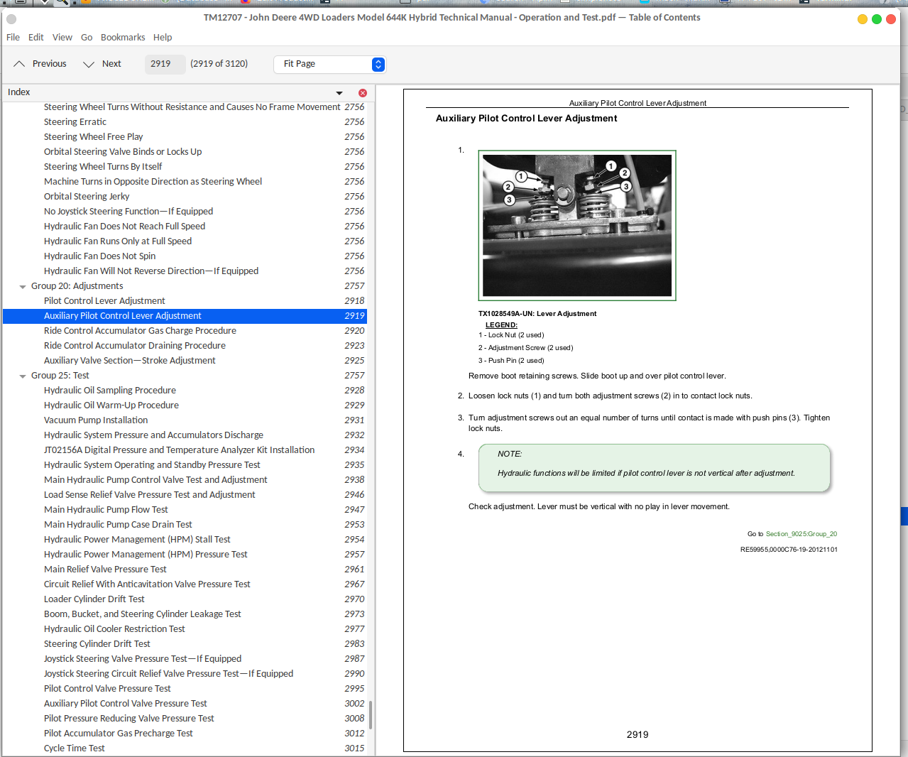
![]()