
John Deere 4WD Loaders 644H & Material Handler 644H MH Repair Service Manual (TM1638)
Complete service repair manual for John Deere 4WD Loaders 644H & Material Handler 644H MH, with all the workshop information to maintain, repair, and service like professional mechanics.
John Deere 4WD Loaders 644H & Material Handler 644H MH workshop service repair manual includes:
* Numbered table of contents easy to use so that you can find the information you need fast.
* Detailed sub-steps expand on repair procedure information
* Numbered instructions guide you through every repair procedure step by step.
* Notes, cautions and warnings throughout each chapter pinpoint critical information.
* Bold figure number help you quickly match illustrations with instructions.
* Detailed illustrations, drawings and photos guide you through every procedure.
* Enlarged inset helps you identify and examine parts in detail.
Total Pages: 826 pages
File Format: PDF/EPUB/MOBI/AZW (PC/Mac/Android/Kindle/iPhone/iPad; bookmarked, ToC, Searchable, Printable)
Language: English
TM1638 - John Deere 4WD Loaders 644H & Material Handler 644H MH Technical Manual (Repair).PDF
TM1638 - John Deere 4WD Loaders 644H & Material Handler 644H MH Technical Manual (Repair).epub
MAIN SECTIONS
Foreword
Technical Information Feedback Form
General Information
Safety Information
Wheels
Powered Wheels And Fasteners
Axles And Suspension Systems
Removal And Installation
Axle Shafts And U-Joints
Axle Shaft, Bearings, Reduction Gears
Hydraulic System
Transmission
Removal And Installation
Gears, Shafts, Bearings And Power Shift Clutch
Hydraulic System
Dealer Fabricated Tools
Engine
Removal And Installation
Engine Auxiliary Systems
Cold Weather Starting Aids
Cooling System
Speed Controls
Intake System
External Exhaust System
External Fuel Supply Systems
Dampener Drive
Elements
Steering System
Hydraulic System
Service Brakes
Active Elements
Hydraulic System
Park Brake
Active Elements
Hydraulic System
Frame Or Supporting Structure
Frame Installation
Frame Bottom Guards
Chassis Weights
Operator’s Station
Removal And Installation
Operator Enclosure
Heating And Air Conditioning
Dealer Fabricated Tools
Sheet Metal And Styling
Hood Or Engine Enclosure
Grille And Grille Housing
Loader
Bucket
tm1638 - 644H Loader, 644H MH Material Handler
Table of Contents
Foreword
Technical Information Feedback Form
Section 00: General Information
Group 0001: Safety Information
4WD Loader Safety Features
Recognize Safety Information
Understand Signal Words
Follow Safety Instructions
Avoid Injury from Rollover Accidents -------------------------------- Wear Your Seat Belt -------------------------------- Do Not Attempt to Jump Clear of Tipping Machine—Serious or Fatal Crushing Injuries Will Result -------------------------------- Machine Will Tip Over Faster Than You Can Jump Free
Avoid Injury from Backover Accidents ------------------------------------ Before Moving Machine, Be Sure All Persons are Clear of Area ------------------------------------ Always Be Alert for Bystanders Moving into the Work Area. Use Horn or Other Signal to Warn Bystanders Before Moving Machine ------------------------------------ When Using a Signal Person, Keep Person in View at all Times. Be Sure Signal Person is Clear Before Backing Up
Avoid Injury from Rollaway Accidents ------------------------------------ To Prevent Rollaway, Always Make Sure Machine is Properly Secured Before Leaving Operator’s Seat ------------------------------------ Death or Serious Injury May Result if You Attempt to Mount or Stop a Moving Machine
Inspect Machine
Use Handholds and Steps
Prevent Machine Runaway
Use Seat Belt Properly
Maintain Seat Belt
Secondary Exits
Travel Safely
Drive Machine Safely
Operate Machine with Caution
Operating on Slopes
Carrying Loads
Avoid Power Lines
Beware of Exhaust Fumes
Keep Riders Off Machine
Handle Fuel Safely—Avoid Fires
Prepare for Emergencies
Handle Starting Fluid Safely
Clean Trash from Machine
Protect Against Flying Debris
Wear Protective Clothing
Protect Against Noise
Handle Chemical Products Safely
Use Safety Lights and Devices
Keep ROPS Installed Properly
Warn Others of Service Work
Practice Safe Maintenance
Support Machine Properly
Remove Paint Before Welding or Heating
Avoid Heating Near Pressurized Fluid Lines
Avoid High-Pressure Fluids
Clean the Machine Regularly
Service Cooling System Safely
Store Attachments Safely
Decommissioning — Proper Recycling and Disposal of Fluids and Components
Group 0003: Torque Values
Metric Bolt and Cap Screw Torque Values
Additional Metric Cap Screw Torque Values
Unified Inch Bolt and Cap Screw Torque Values
Service Recommendations for 37° Flare and 30° Cone Seat Connectors
Service Recommendations for O-Ring Boss Fittings
O-Ring Boss Fittings in Aluminum Housing Service Recommendations—Excavators
Service Recommendations for Flared Connections—Straight or Tapered Threads
Service Recommendations for Flat Face O-Ring Seal Fittings
O-Ring Face Seal Fittings With SAE Inch Hex Nut and Stud End for High-Pressure Service Recommendations
O-Ring Face Seal Fittings With Metric Hex Nut and Stud End for Standard Pressure Service Recommendations
O-Ring Face Seal Fittings With Metric Hex Nut and Stud End for High-Pressure Service Recommendations
Service Recommendations for Metric Series Four Bolt Flange Fitting
Service Recommendations For Inch Series Four Bolt Flange Fittings
Inch Series Four Bolt Flange Fitting for High-Pressure Service Recommendations
Service Recommendations For Non-Restricted Banjo (Adjustable) Fittings
Service Recommendations For O-Ring Boss Fittings With Shoulder
Metric 24° O-Ring Seal DIN 20078 Service Recommendations
Section 01: Wheels
Group 0110: Powered Wheels And Fasteners
Remove And Install Wheel
Remove Tire
Install Tire
Section 02: Axles And Suspension Systems
Group 0200: Removal And Installation
Remove And Install Front Axle And Differential
Remove Rear Axle And Differential
Install Rear Axle And Differential
Disassemble And Assemble Axle Oscillating Supports
Group 0225: Axle Shafts And U-Joints
Remove And Install Universal Joint And Universal Drive Shaft
Disassemble, Inspect, And Assemble Universal Joint And Universal Drive Shaft
Group 0250: Axle Shaft, Bearings, Reduction Gears
Essential Tools
Service Equipment And Tools
Other Material
Specifications
Install Final Drive Assembly In Repair Stand
Remove Final Drive Assembly From Repair Stand
Remove And Install Oscillating Support Wear Sleeves
Remove Final Drive Assembly
Install Final Drive Assembly
Disassemble Final Drive Assembly
Inspect Final Drive Assembly
Assemble Final Drive Assembly
Replace Brakes
Remove Differential Case Cover
Install Differential Case Cover
Remove Differential
Adjust Differential Preload And Backlash
Install Differential
Hydraulic Diff-Lock Differential Cross-Sectional View
Disassemble, Inspect, And Assemble Hydraulic Diff-Lock Differential
Standard Differential Cross-Sectional View
Disassemble, Inspect, And Assemble Standard Differential
Limited Slip Differential Cross-Sectional View
Disassemble And Inspect Limited Slip Differential
Assemble Differential
Measure End Play Gap Limited Slip Differential
Proceed With Differential Assembly
Input Pinion Shaft Cross-Sectional View
Remove Input Shaft
Install Input Pinion Shaft
Determine Differential Drive Shaft Cone Point Shim Pack
Assemble Input Drive
Adjust Input Pinion Shaft
Continue Input Shaft Installation
Axle Disconnect Input Shaft Cross-Sectional View
Remove And Install Disconnect Axle Disconnect Input Shaft
Disassemble, Inspect, And Assemble Axle Disconnect Input Shaft
Group 0260: Hydraulic System
Remove And Install Differential Lock Solenoid Valve
Section 03: Transmission
Group 0300: Removal And Installation
Remove And Install Transmission
Group 0350: Gears, Shafts, Bearings And Power Shift Clutch
Remove Torque Converter (Engine Removed)
Install Torque Converter (Engine Removed)
Remove Torque Converter And Housing
Install Torque Converter And Housing
Remove Clutches, Input And Output Shafts
Install Clutches, Input, And Output Shafts
Disassemble Clutch Pack KV And KR
Assemble Clutch Pack KV And KR
Disassemble Clutch Pack K1, K2, And K3
Assemble Clutch Pack K1, K2, And K3
Disassemble Clutch Pack K4
Assemble Clutch Pack K4
Disassemble Input Shaft
Assemble Input Shaft
Group 0360: Hydraulic System
Remove Transmission Pump
Remove And Install Converter Minimum Pressure Regulator Valve
Install Transmission Pump
Remove Transmission Hydraulic Control Valve
Install Transmission Hydraulic Control Valve
Transmission Hydraulic Control Valve Cross Section View
Disassemble Transmission Control Valve
Assemble Transmission Control Valve
Remove, Disassemble, And Install Converter Relief Valve
Transmission Internal Oil Pipes and Tubes Remove and Install
Group 0399: Dealer Fabricated Tools
DFT1149 Pre-Load Clutch Pack Compression Ring Tool
DFT1063 Lifting Bracket
DFT1158 Torque Converter Adapter Plate
Section 04: Engine
Group 0400: Removal And Installation
6081 John Deere Engine—Use CTM86
6081 John Deere Engine—Use CTM134 Operation And Diagnostics
Remove and Install Engine
Section 05: Engine Auxiliary Systems
Group 0505: Cold Weather Starting Aids
Remove And Install Fluid Starting Aid Assembly
Remove And Install Engine Coolant Heater
Group 0510: Cooling System
Remove And Install Serpentine Belt
Remove And Install Fan And Fan Drive
Remove And Install Radiator, Oil, And Air Cooler
Disassemble And Assemble Radiator, Oil, And Air Cooler (S.N. —585560)
Group 0515: Speed Controls
Remove And Install Speed Control Linkage
Group 0520: Intake System
Remove And Install Air Cleaner
Group 0530: External Exhaust System
Remove And Install Muffler
Group 0560: External Fuel Supply Systems
Remove And Install Fuel Tank
Section 07: Dampener Drive
Group 0752: Elements
Remove And Install Dampener
Section 09: Steering System
Group 0960: Hydraulic System
Essential Tools
Service Equipment and Tools
Other Material
Specifications
Remove And Install Steering Valve
Remove And Install Steering Column
Remove And Install Steering Cylinder
Disassemble and Assemble Steering Cylinder
Remove And Install Steering Cylinder Bushings
Section 10: Service Brakes
Group 1011: Active Elements
Inspect External Service Brakes
Remove And Install Brake Assembly
Group 1060: Hydraulic System
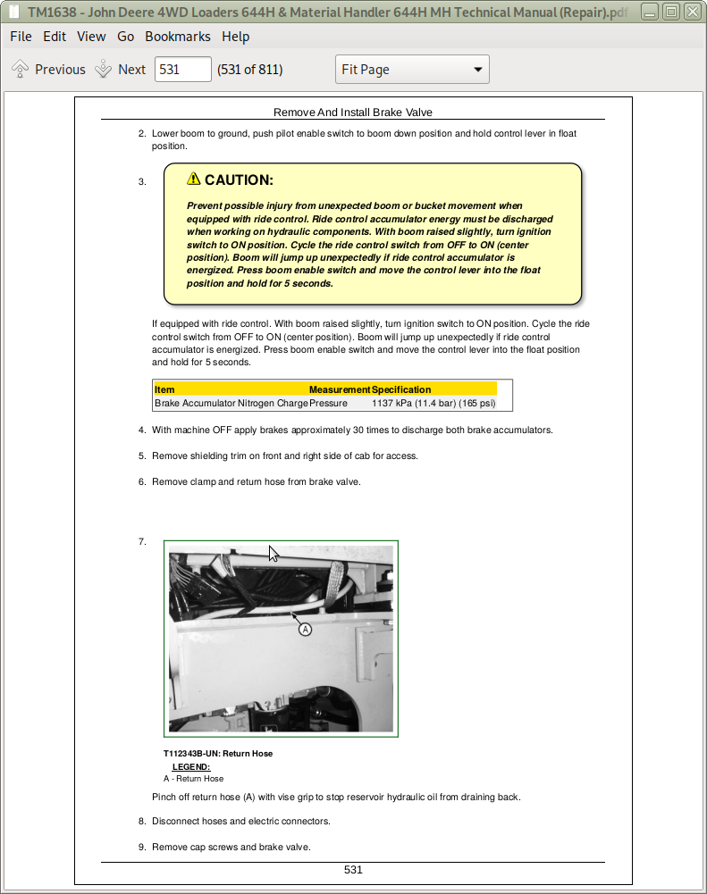
Remove And Install Brake Valve
Remove And Install Brake Accumulator
Section 11: Park Brake
Group 1111: Active Elements
Remove And Install Park Brake
Disassemble And Assemble Park Brake
Group 1160: Hydraulic System
Remove And Install Park Brake Release Solenoid Valve
Remove And Install Park Brake Pressure Switch
Section 17: Frame Or Supporting Structure
Group 1740: Frame Installation
Weld Major Structure
Separate Engine And Loader Frame
Remove And Install Upper Pivot Bearing And Seals
Remove And Install Lower Pivot Bearing And Seals
Group 1746: Frame Bottom Guards
Remove And Install Fuel Tank Guard
Remove And Install Front Axle Guard
Remove And Install Transmission Bottom Guard
Remove And Install Transmission Side Guards
Group 1749: Chassis Weights
Remove And Install Counterweights
Section 18: Operator’s Station
Group 1800: Removal And Installation
Remove And Install Cab Or Canopy
Group 1810: Operator Enclosure
Adjust Front Windshield Wiper
Group 1830: Heating And Air Conditioning
R134a Refrigerant Cautions
R134a Compressor Oil Charge Check
R134a Compressor Oil Removal
R134a Component Oil Charge
Leak Testing
Refrigerant Hoses And Tubing Inspection
R134a Refrigerant Recovery, Recycling And Charging Station Installation Procedure
Recover R134a System
Evacuate R134a System
Charge R134a System
Air Conditioner System Cleaning Procedures
Purge Air Conditioner System
Flush Air Conditioner System
Air Conditioning Module With Heater/Evaporator Coil
Remove And Install Heater/Evaporator Core
Remove And Install Expansion Valve
Remove And Install Freeze Control Switch
Bench Test Freeze Control Switch
Remove And Install Heater Control Valve
Heater Control Valve Leak Check
Remove And Install Main Blower Assembly
Remove And Install Pressurizer Motor Assembly
Remove And Install Receiver-Dryer And Condenser
Remove And Install High And Low Pressure Switches
Remove And Install Fresh Air Filter
Remove And Install Recirculating Air Filter
Remove And Install Compressor
Disassemble And Assemble Compressor Clutch—R134a
Check Clutch Hub Clearance—R134a
Inspect Compressor Manifold—R134a
Disassemble, Inspect, And Assemble Compressor—R134a
Group 1899: Dealer Fabricated Tools
DFRW20 Compressor Holding Fixture
Section 19: Sheet Metal And Styling
Group 1910: Hood Or Engine Enclosure
Remove And Install Hood
Remove And Install Engine Side Shields
Group 1921: Grille And Grille Housing
Remove And Install Grille And Grille Housing
Section 31: Loader
Group 3102: Bucket
Ride Control Accumulator Safety
Remove And Install Bucket Tooth Shanks And Tips
Remove And Install Bucket
Remove And Install Welded-On Bucket Cutting Edges
Remove And Install Bolt-On Cutting Edges And Wear Plates
Repair Cracked Cutting Edge
Group 3140: Frames
Service Equipment And Tools
Other Material
Specifications
Remove And Install Loader Bucket Tilt Linkage
Remove And Install Bucket Linkage Seals And Bushings
Remove And Install Loader Boom Bushings And Seals
Group 3160: Hydraulic System
Other Material
Specifications
Remove And Install Loader Hydraulic Pump
Inspect And Assemble Hydraulic Pump Disassemble
Remove And Install Hydraulic Pump Control Valve
Disassemble And Assemble Hydraulic Pump Control Valve
Hydraulic Pump Stroke Limiter Adjustment
Remove And Install Loader Control Valve
Disassemble And Assemble Loader Control Valve
Disassemble And Assemble Auxiliary Valve Section And Bucket Section
Disassemble And Assemble Boom Valve Section
Disassemble And Assemble Relief Valve
Disassemble And Assemble Bucket Circuit Relief Valve
Disassemble And Assemble Load Sense Relief Valve
Disassemble And Assemble Boom Circuit Relief Valve
Disassemble and Assemble Boom and Bucket Cylinder—185 Series
Remove And Install Boom And Bucket Cylinder Bushings And Seals
Remove And Install Hydraulic Reservoir
Hydraulic Oil Clean-Up Procedure Using Portable Filter Caddy
Pilot Controller Repair (Single Lever Controller)
Pilot Controller Repair (Two Lever Controller) (S.N. —585560)
Pilot Controller Repair (Two Lever Controller) (S.N. 585561—)
Remove And Install Pressure Reducing Valve Manifold
Remove And Install Pressure Reducing Valve
Disassemble And Assemble Pressure Reducing Valve
Remove And Install Boom Down Solenoid Valve
Remove And Install Differential Lock Solenoid Valve
Remove And Install Pilot Enable Solenoid Valve
Ride Control Valve Remove and Install
Ride Control Valve Disassemble and Assemble
Ride Control Accumulator Remove and Install
Ride Control Accumulator Disassemble and Assemble
Remove And Install Pin Disconnect/Axle Disconnect Valve
Disassemble And Assemble Pin Disconnect Valve
Disassemble And Assemble Axle Disconnect Valve
Group 3199: Dealer Fabricated Tools
DFT1132 Hydraulic Pump Removal And Installation Tool
Frames
Hydraulic System
Dealer Fabricated Tools
![]()