
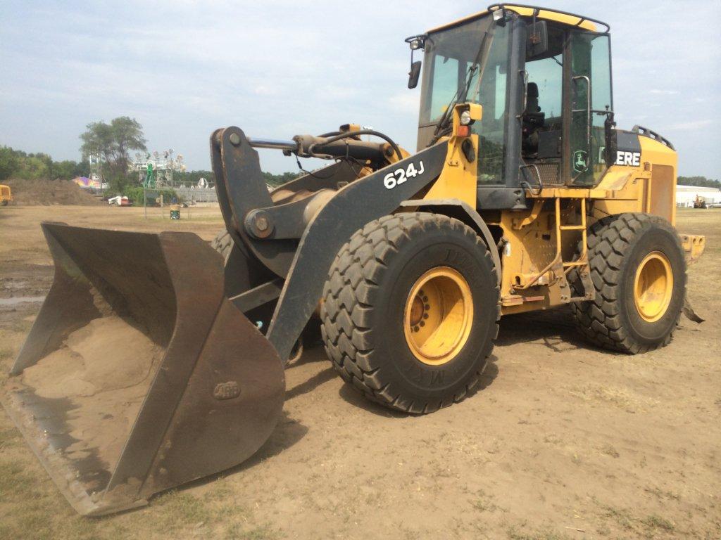
John Deere 4WD Loaders 624J Operation and Test Service Manual (TM10230)
TM10230 - John Deere 4WD Loaders 624J Technical Manual - Repair.PDF
Complete Operation and Test manual for John Deere 4WD Loaders 624J (S.N.from 611797), with all the shop information to maintain, diagnostic, repair, refurbish/rebuild like professional mechanics.
John Deere 4WD Loaders 624J workshop Operation and Test manual includes:
* Numbered table of contents easy to use so that you can find the information you need fast.
* Detailed sub-steps expand on repair procedure information
* Numbered instructions guide you through every repair procedure step by step.
* Troubleshooting and electrical service procedures are combined with detailed wiring diagrams for ease of use.
* Notes, cautions and warnings throughout each chapter pinpoint critical information.
* Bold figure number help you quickly match illustrations with instructions.
* Detailed illustrations, drawings and photos guide you through every procedure.
* Enlarged inset helps you identify and examine parts in detail.
Total Pages: 1,340 pages
File Format: PDF (bookmarked, ToC, Searchable, Printable, high quality)
Language: English
MAIN SECTIONS
Foreword
Technical Information Feedback Form
General Information
Safety Information
Diagnostic Trouble Codes (DTC)
CAN Monitor Unit (CMU) Diagnostic Trouble Codes
Engine Control Unit (ECU) Diagnostic Trouble Codes
Transmission Control Unit (TCU) Diagnostic Trouble Codes
Flex Load Controller (FLC) Diagnostic Trouble Codes
Sealed Switch Module (SSM) Diagnostic Trouble Codes
Operational Checkout Procedure
Operational Checkout Procedure
Engine
Theory of Operation
Diagnostic Information
Tests
Electrical System
System Information
System Diagrams
Sub-System Diagnostics
References
Power Train
Theory of Operation
Diagnostic Information
Adjustments
Tests
Hydraulic System
Theory of Operation
Diagnostic Information
Adjustments
Test
Heating And Air Conditioning
Theory Of Operation
Diagnostic Information
Tests
TABLE OF CONTENTS - Expanded View
tm10230 - 624J Loader (S.N. 611797— )
Table of Contents
Foreword
Technical Information Feedback Form
General Information
Safety Information
Recognize Safety Information
Follow Safety Instructions
Operate Only If Qualified
Wear Protective Equipment
Avoid Unauthorized Machine Modifications
Add Cab Guarding For Special Uses
Inspect Machine
Stay Clear of Moving Parts
Avoid High-Pressure Fluids
Avoid High-Pressure Oils
Beware of Exhaust Fumes
Prevent Fires
Prevent Battery Explosions
Handle Chemical Products Safely
Dispose of Waste Properly
Prepare for Emergencies
Use Steps and Handholds Correctly
Start Only From Operator's Seat
Use and Maintain Seat Belt
Prevent Unintended Machine Movement
Avoid Work Site Hazards
Use Special Care When Operating Loader
Keep Riders Off Machine
Avoid Backover Accidents
Avoid Machine Tip Over
Operating on Slopes
Operating or Traveling On Public Roads
Inspect and Maintain ROPS
Add and Operate Attachments Safely
Prevent Unintended Detonation of Explosive Devices
Park And Prepare For Service Safely
Service Cooling System Safely
Remove Paint Before Welding or Heating
Make Welding Repairs Safely
Drive Metal Pins Safely
Diagnostic Trouble Codes (DTC)
CAN Monitor Unit (CMU) Diagnostic Trouble Codes
CAN Monitor Unit (CMU) Diagnostic Trouble Codes
000829.05 - Fuel Level Open or Short
002000.09 - Missing Message From ECU
002003.09 - Missing Message From TCU
002033.09 - Missing Message From FLC
002140.09 - Missing Message From SSM
002367.04 - Left Turn Switch Short to Ground
002369.04 - Right Turn Switch Short to Ground
524250.31 - Inspect Park Brake
Engine Control Unit (ECU) Diagnostic Trouble Codes
Engine Control Unit (ECU) Diagnostic Trouble Codes
000107.00 - Eng Air Filter Restricted
000171.03 - Ambient Air Open Circuit
000171.04 - Ambient Air Short to Gnd
000627.01 - ECU Unswitch Short to GND
001253.13 - Injector Cal Required
002003.09 - CAN Comm Lost for TCU
002033.09 - CAN Comm Lost for FLC
Transmission Control Unit (TCU) Diagnostic Trouble Codes
Transmission Control Unit (TCU) Diagnostic Trouble Codes
002023.09 - CAN Comm Lost for CMU
002033.09 - CAN Comm Lost for FLC
522344.00 - Converter Overtemp
522350.15 - Input Torque Overload
522364.07 - Trans Clutch Calibr Failed
522364.13 - Trans Clutch Calibr Fault
522365.13 - Limp Home Mode
522366.13 - Application Invalid
522367.13 - TCU Configuration Invalid
522368.02 - Memory Failure
522369.03 - Remote Display Short to Power
522369.04 - Remote Display Short to Ground
522370.02 - TCU VP2 Short Circuit
522371.02 - TCU VP1 Short Circuit
522373.03 - Power Supply High Voltage
522373.04 - Power Supply Low Voltage
522374.03 - Sensor Supply Short to Power
522374.04 - Sensor Supply Short to Gnd
522375.00 - Trans Oil Filter Restricted
522376.00 - Trans Oil Temp Max Value
522379.03 - Park Brake Solenoid Short to Power
522379.04 - Park Brake Solenoid Short to Gnd
522379.05 - Park Brake Solenoid Open Circuit
522382.03 - Backup Alarm Short to Power
522382.04 - Backup Alarm Short to Gnd
522382.05 - Backup Alarm Open Circuit
522383.02 - Clutch KR Slippage
522383.03 - Clutch Rev Sol Short to Power
522383.04 - Clutch Rev Sol Short to Gnd
522383.05 - Clutch Rev Sol Open Circuit
522386.02 - Clutch KV Slippage
522386.03 - Clutch Fwd Sol Short to Power
522386.04 - Clutch Fwd Sol Short to Gnd
522386.05 - Clutch Fwd Sol Solenoid Open
522389.02 - Clutch K4 Slippage
522389.03 - Clutch K4 Sol Short to Power
522389.04 - Clutch K4 Sol Short to Gnd
522389.05 - Clutch K4 Sol Open Circuit
522392.02 - Clutch K3 Slippage
522392.03 - Clutch K3 Sol Short to Power
522392.04 - Clutch K3 Sol Short to Gnd
522392.05 - Clutch K3 Sol Open Circuit
522395.02 - Clutch K2 Slippage
522395.03 - Clutch K2 Sol Short to Power
522395.04 - Clutch K2 Sol Short to Gnd
522395.05 - Clutch K2 Sol Open Circuit
522399.02 - Clutch K1 Slippage
522399.03 - Clutch K1 Sol Short to Power
522399.04 - Clutch K1 Sol Short to Gnd
522399.05 - Clutch K1 Sol Open Circuit
522401.02 - Trans Speed Sensor Fault
522401.03 - Output Shaft Open or Short
522401.04 - Output Shaft Short to Gnd
522401.12 - Output Shaft Fault
522401.15 - Output Shaft Overspeed
522402.03 - Clutch Speed Open or Short
522402.04 - Clutch Speed Short to Gnd
522402.12 - Clutch Speed Sensor Fault
522403.03 - Conv Output Spd Open or Short
522403.04 - Conv Output Spd Short to Gnd
522403.12 - Conv Output Spd Fault
522404.03 - Conv Input Spd Open or Short
522404.04 - Conv Input Spd Short to Gnd
522404.12 - Conv Input Spd Fault
522406.03 - Trans Oil Temp Open or Short
522406.04 - Trans Oil Temp Short to Gnd
522407.03 - Clutch Cutoff Short to Power
522407.04 - Clutch Cutoff Open or Short
522409.05 - 2nd FNR Open Circuit
522409.12 - 2nd FNR Mult Inputs
522411.05 - 1st FNR Open Circuit
522411.12 - 1st FNR Mult Inputs
522412.12 - Gear Selection Error
522419.02 - Clutch Cutoff Disabled
522420.02 - Manual Downshift Disabled
522421.02 - Auto To 1st Disabled
524048.00 - Trans Output Torque Exceeded
524049.00 - Trans Input Torque Exceeded
524287.00 - Configure Machine Model
Flex Load Controller (FLC) Diagnostic Trouble Codes
Flex Load Controller (FLC) Diagnostic Trouble Codes
000117.01 - Brake Pressure Low
000167.16 - Alternator High Voltage
000167.18 - Alternator Low Voltage
000168.16 - High Battery Voltage
000168.18 - Low Battery Voltage
000444.05 - 12V Cntr Tap Open or Short
000444.18 - Battery Voltage Imbalance
000544.19 - Refer Torq Mis-Match
000628.12 - Controller Not Programmed
000774.04 - JS Upshift Short to Gnd
000774.10 - JS Upshift Button Stuck
000775.04 - JS Downshift Short to Gnd
000775.10 - JS Downshift Button Stuck
000785.03 - Pilot Solenoid Short to Power
000785.05 - Pilot Solenoid Open Circuit
000785.06 - Pilot Solenoid High Current
000880.03 - Brake Lights Short to Power
000880.05 - Brake Lights Open Circuit
000880.06 - Brake Lights High Current
000977.03 - Rev Fan Solenoid Short to Power
000977.05 - Rev Fan Sol Open Circuit
000977.06 - Rev Fan Sol High Current
001045.04 - Brake Lt Sw Shorted to Gnd
001069.02 - Tire Size Incorrect
001071.31 - Fan Speed Sol Circuit Fault
001075.00 - Fuel Pump On Too Long
001079.04 - FLC Sensor 1 Voltage Low
001080.04 - FLC Sensor 2 Voltage Low
001638.00 - Hydraulic Oil High Temp
001638.04 - Hyd Oil Temp Circuit Short to Gnd
001713.01 - Hyd Oil Filter Restricted
001762.03 - Hyd Pressure Short to Power
001762.04 - Hyd Pressure Open or Short
002000.09 - CAN Comm Lost for ECU
002003.09 - CAN Comm Lost for TCU
002023.09 - CAN Comm Lost for CMU
002140.09 - CAN Comm Lost for SSM
002350.05 - Drive Lamps Open or Short
002350.06 - Drive Lamps High Current
002355.05 - Front Work Lts Open or Short
002355.06 - Front Work Lts High Current
002356.05 - Front Work Lts Open or Short
002356.06 - Front Work Lts High Current
002362.05 - Rear Work Lts Open or Short
002362.06 - Rear Work Lts High Current
002368.03 - Left Turn Lts Circuit Short to Power
002368.05 - Left Turn Lts Open Circuit
002368.06 - Left Turn Lts Circuit High Current
002370.03 - Right Turn Lts Short to Power
002370.05 - Right Turn Lts Open Circuit
002370.06 - Right Turn Lts High Current
002378.03 - Marker/Tail Lts Short to Power
002378.05 - Marker/Tail Lts Open Circuit
002378.06 - Marker/Tail Lts High Current
002386.06 - Beacon Light High Current
002697.02 - JS Mag Out of Range
002875.04 - 4-Way Flash Sw Short to Gnd
299261.02 - Machine Config Invalid
522431.02 - Memory Test Failure
522432.05 - R Wiper H-Spd Open Circuit
522432.06 - R Wiper H-Spd High Current
522433.05 - R Wiper L-Spd Open or Short
522433.06 - R Wiper L-Spd High Current
522434.05 - F Wiper L-Spd Open or Short
522434.06 - F Wiper L-Spd High Current
522435.05 - F Wiper H-Spd Open Circuit
522435.06 - F Wiper H-Spd High Current
522436.03 - Bucket Pos Short to Power
522436.04 - Bucket Pos Open or Short
522437.04 - RTDig Switch 1 Short to Gnd
522438.03 - Pin Disc Sol Short to Power
522438.05 - Pin Disc Sol Open Circuit
522438.06 - Pin Disc Sol High Current
522796.05 - R Washer Pump Open Circuit
522796.06 - R Washer Pump High Current
522797.05 - F Washer Pump Open Circuit
522797.06 - F Washer Pump High Current
523137.04 - Steering Press Sw Shrt to Gnd
523214.05 - No Voltage to FLC on VP6
523215.05 - No Voltage to FLC on VP5
523216.05 - No Voltage to FLC on VP4
523217.05 - No Voltage to FLC on VP3
523218.05 - No Voltage to FLC on VP2
523219.05 - No Voltage to FLC on VP1
523436.17 - FLC Watchdog Timed Out
523577.03 - 2nd Steer Pump Short to Power
523577.05 - 2nd Steer Pump Open Circuit
523577.06 - 2nd Steer Pump High Current
523786.03 - Boom Position Short to Power
523786.04 - Boom Position Open or Short
523837.01 - Brake Pressure Low-Rear
523837.04 - Rr Brake Pressure Open or Short
523840.01 - Brake Pressure Low-Front
523840.03 - Ft Brake Pressure Short to Power
523840.04 - Ft Brake Pressure Open or Short
523911.31 - Hyd Pwr Sol Circuit Fault
523948.03 - Ride Contrl Sol Short to Power
523948.05 - Ride Contrl Sol Open Circuit
523948.06 - Ride Contrl Sol High Current
524265.19 - Check Sum Error
Sealed Switch Module (SSM) Diagnostic Trouble Codes
Sealed Switch Module (SSM) Diagnostic Trouble Codes
000628.12 - Controller Not Programmed
000629.12 - SSM Watchdog Time Out
000639.12 - SSM Lost Message
000639.19 - SSM Lost CAN Communications
002033.09 - SSM Lost Communications
523523.10 - Rear Wiper Keypad Stuck
523524.10 - Front Wiper Keypad Stuck
523525.10 - Front Washer Keypad Stuck
523526.10 - Reverse Fan Keypad Stuck
523527.10 - Pin Disconnect Keypad Stuck
523528.10 - A/C Keypad Stuck
523529.10 - Work Lights Keypad Stuck
523530.10 - Beacon Light Keypad Stuck
523532.10 - Spin Control Keypad Stuck
523533.10 - Clutch Cut-Off Keypad Stuck
523534.10 - Pilot Enable Keypad Stuck
523535.10 - Ride Control Keypad Stuck
523536.10 - Auto Transmission Keypad Stuck
523537.10 - Drive Lights Keypad Stuck
523538.10 - Keypad Not Used
523607.10 - Return to Dig Keypad Stuck
523608.10 - BHKO Keypad Stuck
523609.10 - RTCarry Keypad Stuck
523610.10 - Rear Washer Keypad Stuck
Operational Checkout Procedure
Operational Checkout Procedure
Operational Checkout
Engine
Theory of Operation
PowerTech Plus™ 6.8L (6068) John Deere Engine
Cold Weather Starting Aid
Diagnostic Information
PowerTech Plus™ 6.8L (6068) John Deere Engine
Engine Cooling System Component Location
Engine Fuel System Component Location
Engine Intake and Exhaust Component Location
Tests
Engine Speed Check and Adjust
Electrical System
System Information
Electrical Diagram Information
System Diagrams
Fuse and Relay Specifications
System Functional Schematic, Wiring Diagram and Component Location Legend
System Functional Schematic and Section Legend
JDLink™ System Functional Schematic—MIG/GTT
JDLink™ System Functional Schematic—MTG/SAT
Loader Frame Harness (W2) Component Location
Loader Frame Harness (W2) Wiring Diagram
Load Center Harness (W3) Component Location
Load Center Harness (W3) Wiring Diagram
Front Console Harness (W4) Component Location
Front Console Harness (W4) Wiring Diagram
Engine Frame Harness (W5) Component Location
Engine Frame Harness (W5) Wiring Diagram
Engine Harness (W6) Component Location
Engine Harness (W6) Wiring Diagram
Transmission Harness (W10) Component Location
Transmission Harness (W10) Wiring Diagram
Rear Frame Harness (W13) Component Location
Rear Frame Harness (W13) Wiring Diagram
Secondary Steering Harness (W17) Component Location
Secondary Steering Harness (W17) Wiring Diagram
Cab Roof Harness (W19) Component Location
Cab Roof Harness (W19) Wiring Diagram
Heater and Air Conditioner Harness (W20) Component Location
Heater and Air Conditioner Harness (W20) Wiring Diagram
JDLink™ System Harnesses Component Location—MIG/GTT
JDLink™ System Harnesses Component Location—MTG/SAT
JDLink™ System Wiring Diagrams—MIG/GTT
JDLink™ System Wiring Diagrams—MTG/SAT
Radio Harness (W34) Component Location
Radio Harness (W34) Wiring Diagram
Sub-System Diagnostics
Starting and Charging Circuit Theory of Operation
Controller Area Network (CAN) Theory of Operation
Engine Control Unit (ECU) Circuit Theory of Operation
Flex Load Controller (FLC) Circuit Theory of Operation
Transmission Control Unit (TCU) Circuit Theory of Operation
CAN Monitor Unit (CMU) Circuit Theory of Operation
References
Diagnostic Trouble Codes (DTC) Quick Reference List
Service ADVISOR Diagnostic Application
Service ADVISOR Connection Procedure
Reading Diagnostic Trouble Codes with Service ADVISOR Diagnostic Application
JDLink™ System Identification
JDLink™ Connection Procedure—If Equipped
CAN Monitor Unit (CMU) Menu Structure—Service Mode
Flex Load Controller (FLC) Fault Exceptions
CAN Circuit Test
Electrical Component Specifications
Transmission Control Valve Solenoid Check
Clutch Cut-Off Sensor Check and Adjustment
Boom Height Kickout/Return-to-Carry Adjustment
Return-To-Dig Adjustment—Z-Bar Linkage
Return-To-Dig Adjustment—Powerllel Linkage
Diagnostic Trouble Codes—After Machine Repair
Change Backup Alarm Volume
Pressure Switches Remove and Install
Alternator Test
Replace (Push Type) Metri-Pack Connectors
Replace METRI-PACK Connectors
Install METRI-PACK Contact
Replace DEUTSCH Connectors
Install DEUTSCH Contact
Replace WEATHER PACK Connector
Install WEATHER PACK Contact
Replace CINCH Connectors
Install CINCH Contact
Repair 32 and 48 Way CINCH Connectors
Remove Connector Body from Blade Terminals
Engine Control Unit (ECU) Remove and Install
Flex Load Controller (FLC) Remove and Install
Transmission Control Unit (TCU) Remove and Install
Sealed Switch Module (SSM) Remove and Install
CAN Monitor Unit (CMU) Remove and Install
Reprogram CAN Monitor Unit (CMU)
Electronic Controller Reconfiguration
Power Train
Theory of Operation
TEAMMATE TEAMMATE is a trademark of Deere & Company Axles
Transmission Clutch Engagement and Solenoids Activated
Power Train Component Operation
Transmission Operation
Transmission Operation—First Gear Forward
Transmission Control Valve Component Operation
Transmission Clutch Modulation
Thermal Bypass Valve Operation
Standard Differential Operation
Differential Lock Operation
Axle Circulation Dual Pump Operation
Park Brake Operation
Diagnostic Information
Transmission Control Circuit—First Forward
Transmission Control System
Power Train Component Location
Transmission System Diagnose Malfunctions
Differential and Axle Diagnose Malfunctions
Service Brake Diagnose Malfunctions
Driveline Diagnose Malfunctions
Park Brake Diagnose Malfunctions
Adjustments
Service Brake Bleeding Procedure
External Service Brake Inspection
Transmission Control Unit (TCU)—Electronic Clutch Calibration
Tests
Transmission Oil Warmup Procedure
Park Brake Pressure Test
Park Brake Drag Test
Transmission Pump Flow Test
Transmission System Pressure Test
Transmission Clutch Pressure Test
Transmission Element Leakage Test
Transmission Lube Pressure Test
Differential Lock Pressure Test
Torque Converter-In Pressure Test
Torque Converter-Out Pressure Test
Torque Converter Relief Pressure Test
Torque Converter-Out Flow Test
Torque Converter Stall Speed Test
Transmission Oil Cooler Thermal Bypass Valve Temperature Test
Transmission Oil Cooler Thermal Bypass Valve Pressure Test
Transmission Oil Cooler Restriction Test
Axle Circulation Dual Pump Flow Test
Axle Breather Test
Hydraulic System
Theory of Operation
Loader Hydraulic System Operation
Hydraulic Pump Operation
Hydraulic Fan Drive Operation
Steering System Component Operation
Steering Valve Operation
Secondary Steering System Operation
Secondary Steering Inlet Manifold Operation
Pressure Reducing Valve Operation
Service Brake Hydraulic System Operation
Service Brake Accumulator Operation
Service Brake Valve Operation
Pin Disconnect Operation
Pilot Control Lever Operation
Control Valve Pilot Orifice Check Valve Operation
Auxiliary Section—Operating And Boom Raise
Loader Control Valve Operation
Boom Section Operation—Boom Down and Steering
Bucket Section Operation—Boom Raise and Bucket Dump
Bucket Section Operation—Boom Raise and Bucket Dump (High Lift Option Only)
Auxiliary Sections—Stroke Adjuster Operation
Outlet Section Operation
Load Sense Circuit Operation—Neutral
Load Sense Circuit Operation—Steering
Load Sense Circuit Operation—Steering and Boom Down
Load Sense Circuit Operation—Boom Raise and Bucket Dump
Relief Valve Operation
Load Sense Relief Valve Operation
Circuit Relief Valve Operation
Anticavitation Valve Operation
Return Filter Operation
Ride Control Operation
Diagnostic Information
Hydraulic System Schematic
Hydraulic System Component Location
Hydraulic System Diagnose Malfunctions
Adjustments
Hydraulic Oil Clean-Up Procedure Using Portable Filter Caddy
Return-to-Dig Adjustment
Return-to-Carry and Boom Height Kickout Adjustment
Pump Load Sense Differential and Standby Pressure Adjustment
Pilot Controller Adjustment—Two Lever Pilot
Ride Control Accumulator Hydraulic Discharge Procedure
Ride Control Accumulator Gas Charge Procedure—If Equipped
Ride Control Accumulator Draining Procedure—If Equipped
Auxiliary Valve Section—Stroke Adjustment
Test
Hydraulic Oil Warmup Procedure
Hydraulic System Pressure and Accumulators Discharge
JT02156A Digital Pressure and Temperature Analyzer Kit Installation
Pump Load Sense Differential and Standby Pressure Test
Maximum System Pressure Test
Hydraulic Pump Flow Test
Hydraulic Pump Case Drain Test
Loader System Relief and Circuit Relief Valve Pressure Test
Loader Cylinder Drift Test
Boom, Bucket and Steering Cylinder Leakage Test
Steering Valve Leakage Test
Steering Valve Drift Test
Secondary Steering Pump Relief Valve Pressure Test
Secondary Steering Manifold Primary Check Valve Leakage Test
Secondary Steering Manifold Secondary Check Valve Leakage Test
Pilot Control Valve Pressure Test—Single Lever
Pilot Control Valve Pressure Test—Two Lever
Pressure Reducing Valve Pressure Test
Cycle Time Test
Brake Accumulator Precharge Test
Boom Down Accumulator Precharge Test
Brake Valve Pressure Test
Brake Valve Leakage Test
Brake Accumulator Inlet Check Valve Leakage Test
Pin Disconnect Pressure Test
Hydraulic Fan Pump Pressure Test
Hydraulic Fan Motor Speed Test
Hydraulic Fan Pump Flow Test
Hydraulic Fan Motor Case Drain Test
Hydraulic Oil Filter Inspection Procedure
Heating And Air Conditioning
Theory Of Operation
Air Conditioning System Cycle Of Operation
Diagnostic Information
Air Conditioning System Diagnose Malfunctions
Heater System Diagnose Malfunctions
Tests
Air Conditioning System Fittings Reference Chart
Refrigerant Cautions and Proper Handling
R134a Refrigerant Cautions
R134a Oil Charge Capacity
R134a Refrigerant Charge Capacity
Refrigerant Hoses And Tubing Inspection
R134a Air Conditioning System Test
Operating Pressure Diagnostic Chart
Air Conditioning High/Low Pressure Switch Test
Freeze Control Switch Test
Refrigerant Leak Testing
![]()