
John Deere 4WD Loaders 544G, 544G LL, 544G TC, 624G, 644G Repair Service Manual (TM1530)

Complete service repair manual for John Deere 4WD Loaders 544G, 544G LL, 544G TC, 624G, 644G, with all the technical information to maintain, service, repair like professional mechanics.
John Deere 4WD Loaders 544G, 544G LL, 544G TC, 624G, 644G workshop service & repair manual includes:
* Numbered table of contents easy to use so that you can find the information you need fast.
* Detailed sub-steps expand on repair procedure information
* Numbered instructions guide you through every repair procedure step by step.
* Notes, cautions and warnings throughout each chapter pinpoint critical information.
* Bold figure number help you quickly match illustrations with instructions.
* Detailed illustrations, drawings and photos guide you through every procedure.
* Enlarged inset helps you identify and examine parts in detail.
TM1530 - John Deere 544G, 544G LL, 544G TC, 624G and 644G 4WD Loader Technical Manual - Repair.PDF
TM1530 - John Deere 544G, 544G LL, 544G TC, 624G and 644G 4WD Loader Technical Manual - Repair.EPUB
Total Pages: 770 pages
File Format: PDF (bookmarked, ToC, Searchable, Printable, high quality) & EPUB/MOBI/AZW for Kindle etc.
Language: English
Notes: for electrical wiring diagrams, please refer to TM1529.
MAIN SECTIONS
Foreword
Help!! Help!! Help!! Help!!
General Information
Safety Information
General Specifications
Torque Values
Fuels And Lubricants
Inspection Procedures
Wheels
Powered Wheels And Fastenings
Axles And Suspension Systems
Removal And Installation
Axle Shafts, Bearings And U-Joints
Hydraulic System
Transmission
Removal And Installation
Control Linkage
Input Drive Shafts And U-Joints
Gear, Shafts, Bearings And Power Shift Clutch
Hydraulic System
Engine
Removal And Installation
Engine Auxiliary Systems
Cold Weather Starting Aids
Cooling System
Speed Controls
Intake System
External Fuel Supply System
Dampener Drive
Elements
Steering System
Secondary Steering
Hydraulic System
Service Brakes
Active Elements
Hydraulic System
Park Brake
Active Elements
Hydraulic System
Equipment Attaching
Drawbar
Electrical Systems
Batteries, Support And Cables
Alternator, Regulator And Charging System Wiring
Lighting System
Wiring Harness And Switches
Motors And Actuators
Frame Or Supporting Structure
Frame Installation
Frame Bottom Guards
Chassis Weights
Operator’s Station
Removal And Installation
Operator Enclosure
Seat And Seat Belt
Heating And Air Conditioning
Loader
Bucket
Frames
Hydraulic System
Dealer Fabricated Tools
tm1530 - 544G, 544G LL, 544G TC, 624G, and 644G Loader
Table of Contents
Foreword
Help!! Help!! Help!! Help!!
Section 00: General Information
Group 01: Safety Information
Handle Fluids Safely—Avoid Fires
Prevent Battery Explosions
Prepare for Emergencies
Prevent Acid Burns
Handle Chemical Products Safely
Avoid High-Pressure Fluids
Park Machine Safely
Support Machine Properly
Wear Protective Clothing
Work in Clean Area
Service Machines Safely
Work In Ventilated Area
Illuminate Work Area Safely
Replace Safety Signs
Use Proper Lifting Equipment
Remove Paint Before Welding or Heating
Avoid Heating Near Pressurized Fluid Lines
Keep ROPS Installed Properly
Service Tires Safely
Avoid Harmful Asbestos Dust
Practice Safe Maintenance
Use Proper Tools
Decommissioning — Proper Recycling and Disposal of Fluids and Components
Live With Safety
Group 02: General Specifications
544G Specifications
544G Drain And Refill Capacities
544G LL Specifications
544G LL Drain And Refill Capacities
544G TC Specifications
544G TC Drain And Refill Capacities
624G Specifications
624G Drain And Refill Capacities
644G Specifications
644G Drain And Refill Capacities
Group 0003: Torque Values
Hardware Torque Specifications
ROPS Torque Specifications
Metric Bolt and Screw Torque Values
Additional Metric Cap Screw Torque Values
Unified Inch Bolt and Screw Torque Values
Check Oil Lines And Fittings
Service Recommendations for O-Ring Boss Fittings
Service Recommendations For Flat Face O-Ring Seal Fittings
Service Recommendations for Metric Series Four Bolt Flange Fitting
Service Recommendations For Inch Series Four Bolt Flange Fittings
Group 0004: Fuels And Lubricants
Fuel Specifications
Storing Fuel
Do Not Use Galvanized Containers
Fuel Tank
Engine Oil
Hydraulic System Oil And Differential Oil
Transmission Oil
Grease
Alternative and Synthetic Lubricants
Lubricant Storage
Mixing of Lubricants
Diesel Engine Coolant (engine with wet sleeve cylinder liners)
Group 0005: Inspection Procedures
Planned Inspection Program I (PIP I)
Planned Inspection Program II (PIP II)
Using The Checklists
Delivery Service
John Deere 544G, 624G And 644G Loader
John Deere 544G, 624G, And 644G Loader
Section 01: Wheels
Group 0110: Powered Wheels And Fastenings
Other Material
Specifications
Remove Tire
Install Tire
544G And 544G TC
544G LL
624G
644G
Section 02: Axles And Suspension Systems
Group 0200: Removal And Installation
John Deere 1200 And 1400 Series Axles—Use CTM138519
Other Material
Specifications
Remove And Install Front Axle And Differential
Remove Rear Axle And Differential
Install Rear Axle And Differential Assembly
Group 0225: Axle Shafts, Bearings And U-Joints
Other Material
Specifications
Disassemble, Inspect, And Assemble Support Bearing And Drive Shaft
Remove And Install Rear Differential Drive Line
Group 0260: Hydraulic System
Specifications
Remove And Install Differential Lock Solenoid Valve
Section 03: Transmission
Group 0300: Removal And Installation
Essential Tools
Service Equipment And Tools
Specifications
Remove And Install Transmission
Group 0315: Control Linkage
Other Material
Specifications
Remove And Install Transmission Shift Lever
Group 0325: Input Drive Shafts And U-Joints
Specifications
Remove, Disassemble, Assemble And Install Transmission Drive Shaft
Group 0350: Gear, Shafts, Bearings And Power Shift Clutch
Essential Tools
Service Equipment And Tools
Other Material
Specifications
Install Repair Stand
Remove And Install Torque Converter
Remove Clutch Packs
Remove And Install Forward And First Drive Gears
Remove And Install Reverse And Second Drive Gears
Remove And Install Third And Fourth Drive Gears
Disassemble And Assemble Clutch Packs
Clutch Packs
Remove And Install Fourth Gear Idler Gear—624G, 644G
Fourth Gear Idler Gear Shaft Orifice Sizes
Install Fourth Gear Idler Gear—544G, 544G LL, 544G TC
Install Third And Fourth Gear Clutch Pack, Adjust End Play
Install Second And Reverse, First And Forward Gear Clutch Packs
Remove And Install Output Flange
Remove And Install Output Shaft And Seals
Remove And Install Output Gear And Oil Shields
Remove And Install Speed Control Magnetic Pickup
Group 0360: Hydraulic System
Essential Tools
Service Equipment And Tools
Other Material
Specifications
Remove Oil Supply Flange And Oil Pump
Disassemble Oil Supply Flange
Assemble Oil Supply Flange
Input Drive Shaft Orifice Sizes
Disassemble Oil Pump
Assemble Oil Pump
Install Oil Pump On Oil Supply Flange
Install Oil Supply Flange And Oil Pump
Remove And Install Converter Minimum Pressure Regulator
Remove And Install Transmission Oil Filter
Remove And Install Suction Oil Strainer
Remove Transmission Control Valve
Repair Transmission Control Valve 544G (SN —542218), 624G (SN —548398), 644G (SN —548302)
Control Valve W/6th Solenoid—544G (SN 548219—), 624G (SN 548398—), 644G (SN 548303—)
Install Transmission Control Valve
Cross Section Of Thermal Bypass Valve
Disassemble And Assemble Thermal Bypass Valve
Section 04: Engine
Group 0400: Removal And Installation
John Deere 6059 Engine Repair—Use CTM8
John Deere 6068 Engine Repair—Use CTM8
John Deere 6076 Engine Repair—Use CTM42
John Deere 6081 Engine Repair—Use CTM134
Special Or Essential Tools
Service Equipment And Tools
Other Material
Specifications
Disconnect Turbocharger Oil Inlet Line
Remove And Install Engine
Section 05: Engine Auxiliary Systems
Group 0505: Cold Weather Starting Aids
Specifications
Remove And Install Starting Aid Solenoid And Nozzle
Remove And Install Engine Coolant Heater
Group 0510: Cooling System
Specifications
Other Material
Remove And Install Compressor Belt (If Equipped) And Fan Belts — 544G, 624G, 644G (SN —557738)
Remove And Install Serpentine Belt — 644G (SN 557739—)
Remove And Install Fan
Remove And Install Radiator
Remove And Install Oil Cooler
Remove And Install Coolant Level Sensor
Group 0515: Speed Controls
Other Material
Specifications
Remove And Install Speed Control Linkage
Speed Control Linkage Adjustment
Fuel Shut-Off Solenoid Adjustment—644G
Group 0520: Intake System
Specifications
Remove And Install Air Filter Elements—544G, 624G
Tighten Air Cleaner Hose Clamps
Remove And Install Air Filter Elements—644G
Test Air Intake System For Leaks
Group 0560: External Fuel Supply System
Other Material
Specifications
Remove And Install Fuel Tank
Remove And Install Primary Filter (Water Separator)
Disassemble And Assemble Primary Filter (Water Separator)
Bleed Fuel System—544G, 624G
Bleed Fuel System—644G
Remove And Install Fuel Shut-Off Solenoid—644G
Fuel Shut-Off Solenoid Adjustment—644G
Section 07: Dampener Drive
Group 0752: Elements
Specifications
Remove And Install Dampener
Section 09: Steering System
Group 0930: Secondary Steering
Specifications
Remove And Install Secondary Steering Pump, Motor And Relay (If Equipped)
Remove And Install Secondary Steering Inlet Manifold (If Equipped)
Disassemble And Assemble Secondary Steering Inlet Manifold (If Equipped)
Group 0960: Hydraulic System
Service Equipment And Tools
Other Material
Specifications
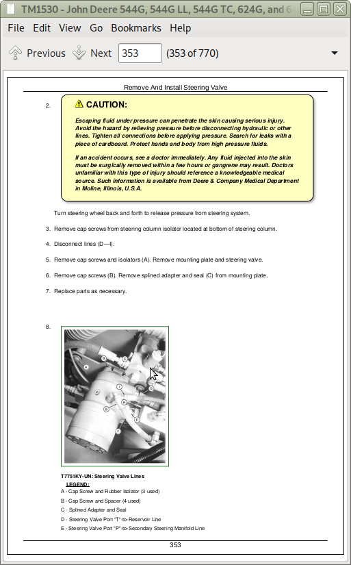
Remove And Install Steering Valve
Disassemble Steering Valve
Cross Section Of Steering Valve
Assemble Steering Valve
Remove And Install Steering Column
Remove And Install Steering Cylinders
Disassemble Steering Cylinder
Cross Section Of Steering Cylinder
Assemble Steering Cylinder
Remove And Install Steering Cylinder Bushings
Remove And Install Priority Valve
Cross Section Of Priority Valve
Disassemble And Assemble Priority Valve
Section 10: Service Brakes
Group 1011: Active Elements
Essential Tools
Inspecting Service Brake Pads
Remove And Install Brake Assembly
Group 1060: Hydraulic System
Service Tools And Equipment
Specifications
Remove And Install Brake Valve
Disassemble And Assemble Brake Valve
Remove And Install Brake Pump
Disassemble Brake Pump
Assemble Brake Pump
Disassemble And Assemble Brake Pump Pressure Compensator
Remove And Install Brake Accumulator
Charge Brake Accumulator
Hydraulic Brake Bleeding Procedure
Remove And Install Pressure Reducing Valve Manifold
Section 11: Park Brake
Group 1111: Active Elements
Specifications
Remove And Install Park Brake Pads
Disassemble And Assemble Park Brake
Adjust Park Brake
Group 1160: Hydraulic System
Specifications
Remove And Install Park Brake Release Solenoid Valve
Remove And Install Park Brake Pressure Switch
Section 15: Equipment Attaching
Group 1511: Drawbar
Specifications
Install Counterweight/Drawbar
Section 16: Electrical Systems
Group 1671: Batteries, Support And Cables
Specifications
Service Batteries Carefully
Test Batteries Using Coolant And Battery Tester
Test Batteries Using High Rate Discharge Test
Charge Battery
Remove And Install Batteries
Remove And Install Battery Disconnect Switch
Group 1672: Alternator, Regulator And Charging System Wiring
Motorola 8EM And 8MR Alternator Repair—Use CTM77
Specifications
Remove And Install Alternator
Group 1673: Lighting System
Specifications
Replace Halogen Bulbs
Remove And Install Lights
Group 1674: Wiring Harness And Switches
Special Or Essential Tools
Other Material
Specifications
Clutch Cut-Off Switch Adjustment
Return-To-Dig Adjustment
Boom Height Kickout Adjustment
Remove And Install Brake Light Switch
Remove And Install Brake Low Pressure Switch
Remove And Install Hydraulic Oil Filter Restriction Switch
Remove And Install Engine Coolant Level Switch
Remove And Install Engine Oil Pressure Switch
Remove And Install Air Filter Restriction Switch
Remove And Install Transmission Oil Pressure Switch
Replace DEUTSCH DEUTSCH is a trademark of the Deutsch Co. Connectors
Install DEUTSCH DEUTSCH is a trademark of the Deutsch Co. Contact
Replace WEATHER PACK WEATHER PACK is a trademark of Packard Electric Connector
Install WEATHER PACK WEATHER PACK is a trademark of Packard Electric. Contact
Remove Connector Body from Blade Terminals
Remove Blade Terminals From Fuse Block
Group 1677: Motors And Actuators
Starting Motor Repair—Use CTM77
Special Or Essential Tools
Specifications
Remove And Install Starting Motor
Section 17: Frame Or Supporting Structure
Group 1740: Frame Installation
Specifications
Welding Repair Of Major Structure
Separate Engine And Loader Frame
Remove And Install Upper Pivot Bearing And Seals
Remove And Install Lower Pivot Bearing And Seals
Group 1746: Frame Bottom Guards
Specifications
Remove And Install Guards
Group 1749: Chassis Weights
Specifications
Remove And Install Counterweights
Section 18: Operator’s Station
Group 1800: Removal And Installation
Special Or Essential Tools
Specifications
Remove And Install Cab Or Canopy
Group 1810: Operator Enclosure
Special Or Essential Tools
Other Material
Specifications
Remove And Install Windowpane And Molding
Remove And Install Windshield Washer
Remove, Disassemble, Assemble And Install Front Windshield Wiper
Adjust Front Windshield Wiper
Remove, Disassemble, Assemble And Install Rear Windshield Wiper
Remove And Install Defroster Fan—(SN —545144)
Remove And Install Defroster Fan—(SN 545145—)
Remove And Install Door Handle And Door/Window Release
Group 1821: Seat And Seat Belt
Specifications
Disassemble And Assemble Seat
Disassemble And Assemble Seat Belt
Group 1830: Heating And Air Conditioning
Special Or Essential Tools
Service Equipment And Tools
Other Material
Service Parts Kits For Compressor
Specifications
Proper Refrigerant Handling
R12 And R134a Refrigerant Cautions
R12 Component Oil Charge
R12 Refrigerant Evacuation And Charging Station Installation Procedure
Recover R12 System
Evacuate R12 System
Charge R12 System
R134a Compressor Oil Information
R134a Compressor Oil Charge Check
R134a Compressor Oil Removal
R134a Component Oil Charge
R134a Refrigerant Recovery/Recycling And Charging Station Installation Procedures
R134a Refrigerant Recovery
Evacuate R134a System
Charge R134a System
Leak Testing
Check And Adjust Compressor Belt Tension — 544G, 624G, 644G (SN —557738)
Remove And Install Compressor And High Pressure Switch
Volumetric Efficiency Test—R12
Shaft Seal Leak Test
Disassemble And Inspect Compressor
Clutch Pulley, Bearing And Hub Inspection
Replace Clutch Pulley Bearing
Replace Shaft Seal Seat
Assemble Compressor
Remove And Install Condenser
Remove And Install Evaporator And Expansion Valve
Remove And Install Receiver/Dryer And Low Pressure Switch
Remove And Install Condenser Fan Motors
Freeze Control Temperature Cycling Switch Bench Test
Disassemble And Assemble Blower Motor
Remove And Install Heater Core
Remove And Install Cab Heater Hoses And Controls
Section 31: Loader
Group 3102: Bucket
Specifications
Remove And Install Bucket Tooth Shanks And Tips
Remove And Install Bucket
Replace Welded Bucket Cutting Edges
Remove And Install Cutting Edges (for Bucket With Wear Plates)
Repair Cracked Cutting Edge
Group 3140: Frames
Service Equipment And Tools
Other Material
Specifications
Remove And Install Bucket Tilt Linkage—544G, 624G And 644G
Remove And Install Bucket Linkage Seals And Bushings—544G, 624G And 644G
Disassemble And Assemble Bucket Tilt Linkage—544G TC And 544G LL
Disassemble And Assemble Tool Carrier—544G TC
Remove And Install Boom Bushings And Shims—544G, 624G And 644G
Remove And Install Boom Bushings And Shims—544G TC And 544G LL
Group 3160: Hydraulic System
Essential Tools
Service Equipment And Tools
Other Material
Specifications
Remove And Install Main Hydraulic Pump
Disassemble, Inspect And Assemble Main Hydraulic Pump
Remove And Install Loader Control Valve
Disassemble And Assemble Loader Control Valve
Disassemble And Assemble Boom Valve (All Units) And Bucket Section (544G TC And 544G LL)
Disassemble And Assemble Auxiliary Valve (All Units) And Bucket Section (544G, 624G, And 644G)
Disassemble And Assemble System Relief Valve
Disassemble And Assemble Anti-Cavitation Valve
Disassemble And Assemble Screw Adjustable Circuit Relief Valve
Service Bucket And Boom Section Pilot Orifice Check Valve
Remove And Install Boom Cylinder
Remove And Install Bucket Cylinder
Disassemble Boom Or Bucket Cylinder
Assemble Boom Or Bucket Cylinder
Remove And Install Bucket Or Boom Cylinder Bushings And Seals
Remove And Install Hydraulic Reservoir
Hydraulic Oil Clean-Up Procedure Using Portable Filter Caddy
Remove And Install Pilot Control Valves (Two Lever Controller)
Disassemble And Assemble Pilot Control Valve (Two-Lever Controller)
Disassemble And Assemble Pilot Control Valve (Two Lever Controller)
Remove And Install Pilot Controller (Single Lever Controller) — 544G, 624G, 644G (SN —563542)
Disassemble Single Lever Pilot Controller — 544G, 624G, 644G (SN —563542)
Assemble Single Lever Controller — 544G, 624G (SN —563542)
Remove And Install Pilot Controller Valve (Single Lever Controller) — 644G (SN 563543—)
Pilot Controller Valve (Single Lever Controller), Cross Section — 644G (SN 563543—)
Disassemble And Assemble Valve (Single Lever Controller) — 644G (SN 563543—)
Replacing Quickshift Switch In Controller Lever — 644G (SN 563543—)
Replace Pilot Control Lever Boot (Joystick) — 644G (SN 536543—)
Replace Pilot Control Lever Boot (Single Lever) — 644G (SN 563543— )
Replace Universal Joint — 644G (SN 563543—)
Replace Seals On Spool Retainers And Inspect Spool Assembly — 644G (SN 563543—)
Pilot Control Valve Pressure Test (Bench) — 644G (SN 563543— )
Remove And Install Pressure Reducing Valve
Remove And Install Boom Down Solenoid Valve
Disassemble And Assemble Pin Disconnect Cylinder—544G TC
Disassemble And Assemble Pin Disconnect Solenoid Valve—544G TC
Ride Control Valve Remove And Install—If Equipped
Ride Control Valve Disassemble And Assemble—If Equipped
Ride Control Accumulator Remove and Install
Ride Control Accumulator Disassemble And Assemble—If Equipped
Section 99: Dealer Fabricated Tools
Group 9900: Dealer Fabricated Tools
DF1055 And JD38002 Yoke Holding Tool
DF1056 Input Pinion Shaft Adjusting Tool
DF1057 Axle Adjusting Tool
DF1025 Oil Supply Flange Back-Off Brackets
DF1026 Pre-Load Clutch Pack Compression Ring Assembly Jig
DF1027 Stand Mounting Bracket
JDG588 Shaft Alignment Tool
DF1044 Air Deflector Bushing
DFT1118 Spanner Wrench
John Deere 4WD Loaders 544G, 544G LL, 544G TC, 624G, 644G Repair Service Manual (TM1530)
![]()