
John Deere 4WD Loader Model 344G and 444G Repair Service Manual (TM1558)
Complete service repair manual for John Deere 344G and 444G 4WD Loader, with all the shop information to maintain, repair, and rebuild like professional mechanics.
John Deere 4WD Loader Model 344G and 444G workshop service & repair manual includes:
* Numbered table of contents easy to use so that you can find the information you need fast.
* Detailed sub-steps expand on repair procedure information
* Numbered instructions guide you through every repair procedure step by step.
* Notes, cautions and warnings throughout each chapter pinpoint critical information.
* Bold figure number help you quickly match illustrations with instructions.
* Detailed illustrations, drawings and photos guide you through every procedure.
* Enlarged inset helps you identify and examine parts in detail.
TM1558 - John Deere 4WD Loader Model 344G and 444G Technical Manual - Repair.PDF
Total Pages: 559 pages
File Format: PDF (PC/Mac/Android/Kindle/iPhone/iPad; bookmarked, ToC, Searchable, Printable)
Language: English ...
MAIN SECTIONS
Foreword
Help!! Help!! Help!! Help!!
General Information
Safety
General Specifications
Torque Values
Fuels And Lubricants
Wheels
Powered Wheels And Fastenings
Axles And Suspension Systems
Removal And Installation
Differential Or Bevel Drive
Axle Shafts, Bearings And U-Joints
Axle Shaft, Bearings And Reduction Gears
Transmission
Removal And Installation
Controls Linkage
Gears, Shafts, Bearings, And Power Shift Clutch
Hydraulic System
Engine
Removal And Installation
Engine Auxiliary Systems
Cold Weather Starting Aids
Cooling Systems
Speed Controls
Intake System
External Fuel Supply Systems
Damper Drive (Flex Coupling)
Elements
Steering System
Secondary Steering
Hydraulic System
Service Brakes
Active Elements
Controls Linkage
Hydraulic System
Park Brake
Active Elements
Hydraulic System
Electrical System
Batteries, Support, And Cables
Alternator, Regulator And Charging System Wiring
Lighting System
Wiring Harness And Switches
System Controls
Motors And Actuators
Frame, Chassis Or Supporting Structure
Frame Installation
Chassis Weights
Operator’s Station
Removal And Installation
Operator Enclosure
Seat And Seat Belt
Heating And Air Conditioning
Main Hydraulic System (Hydraulic Reservoir)
Removal And Installation
Loader
Bucket
Controls Linkage
Frames
Hydraulic System
Dealer Fabricated Tools
tm1558 - 344g and 444g loader repair
Table of Contents
Foreword
Help!! Help!! Help!! Help!!
Section 00: General Information
Group 0001: Safety
Handle Fluids Safely-Avoid Fires
Prevent Battery Explosions
Prepare for Emergencies
Prevent Acid Burns
Handle Chemical Products Safely
Avoid High-Pressure Fluids
Park Machine Safely
Support Machine Properly
Wear Protective Clothing
Work in Clean Area
Service Machines Safely
Work In Ventilated Area
Illuminate Work Area Safely
Replace Safety Signs
Use Proper Lifting Equipment
Remove Paint Before Welding or Heating
Avoid Heating Near Pressurized Fluid Lines
Keep ROPS Installed Properly
Service Tires Safely
Avoid Harmful Asbestos Dust
Practice Safe Maintenance
Use Proper Tools
Dispose of Waste Properly
Live With Safety
Group 0002: General Specifications
344G Loader
344G Loader Operating Information
Loader Specifications-344G
Drain And Refill Capacities-344G
444G Loader
444G Loader Operating Information
Loader Specifications-444G
Drain And Refill Capacities-444G
Group 0003: Torque Values
Hardware Torque Specifications
ROPS Torque Specifications
Metric Bolt and Cap Screw Torque Values
Additional Metric Cap Screw Torque Values
Unified Inch Bolt and Cap Screw Torque Values
Check Oil Lines And Fittings
Service Recommendations for 37° Flare and 30° Cone Seat Connectors
Service Recommendations for O-Ring Boss Fittings
Service Recommendations for Flat Face O-Ring Seal Fittings
Service Recommendations for Metric Series Four Bolt Flange Fitting
Service Recommendations For Inch Series Four Bolt Flange Fittings
Group 0004: Fuels And Lubricants
Fuel Specifications
Low Sulfur Diesel Fuel Conditioner
Storing Fuel
Do Not Use Galvanized Containers
Fuel Tank
Engine Oil
Power Shift (HI-LO) Transmission And Brake System Oil
Hydraulic/Hydrostatic System Oil
Differential Oil
Fuel Specifications
Alternative and Synthetic Lubricants
Mixing of Lubricants
Lubricant Storage
Engine Coolant
Section 01: Wheels
Group 0110: Powered Wheels And Fastenings
Service Equipment And Tools
Specifications
Remove Wheel
Remove And Install Tire
Install Wheel
Section 02: Axles And Suspension Systems
Group 0200: Removal And Installation
Service Equipment And Tools
Specifications
Remove And Install Front Axle And Differential
Remove And Install Rear Axle And Differential
Replace Rear Axle Oscillating Support Bushings
Group 0210: Differential Or Bevel Drive
Service Equipment And Tools
Other Material
Specifications
Remove Differential Case Cover
Remove Axle Housing
Remove Input Quill And Shaft
Exploded View Of Input Quill And Shaft
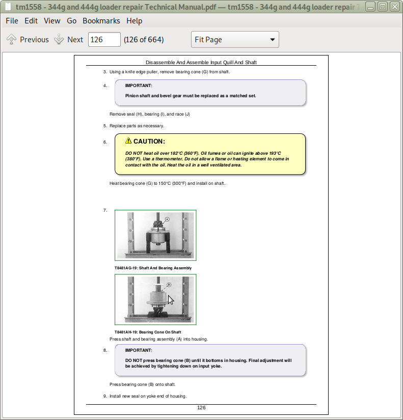
Disassemble And Assemble Input Quill And Shaft
Adjust Pinion Shaft
Adjust Cone Point
Install Input Quill And Shaft
Adjust Differential Backlash
Check Tooth Bearing Pattern
Remove Standard Differential
Disassemble Standard Differential
Remove And Install Bevel Gear
Exploded View Of Standard Differential
Install Standard Differential
Remove Differential Lock Differential
Disassemble Differential Lock Differential
Assemble Differential Lock Differential
Install Differential Lock Differential
Adjust Differential Preload
Install Input Quill And Shaft
Install Axle Housing
Install Cover
Group 0225: Axle Shafts, Bearings And U-Joints
Other Material
Specifications
Remove And Install Drive Shafts And U-Joint
Disassemble And Assemble Front Drive Shaft And Bearing Carrier
Disassemble And Assemble Center Drive Shaft
Disassemble And Assemble Rear Universal Joint
Group 0250: Axle Shaft, Bearings And Reduction Gears
Service Equipment And Tools
Other Material
Specifications
Remove Axle Housing
Planet Pinion Carrier And Axle Shaft-Cross Section
Planet Pinion Carrier And Axle Shaft-Exploded View
Disassemble Planet Pinion Carrier
Inspect Planet Pinion Components
Assemble Planet Pinion Carrier
Remove Axle Shaft To Disassemble Axle Housing
Inspect Axle Housing And Shaft
Disassemble Axle Housing
Assemble Axle Shaft And Housing
Install Axle Housing
Section 03: Transmission
Group 0300: Removal And Installation
Service Equipment And Tools
Other Material
Specifications
Remove And Install Hydrostatic Motor
Remove And Install HI-LO Transmission
Remove And Install Hydrostatic Pump
HST Start-Up Procedure
Flush Hydrostatic Motor Hoses And Hydrostatic Oil Cooler
Check HI-LO Transmission Oil Level
Group 0315: Controls Linkage
Other Material
Specifications
Front Axle Disconnect Cable Adjustment
Disassemble And Assemble Brake Pedal And Inching Pedal Linkage
Adjust Brake Pedal And Inching Pedal Linkage
Group 0350: Gears, Shafts, Bearings, And Power Shift Clutch
Service Equipment And Tools
Other Material
Specifications
Disassemble HI-LO Transmission
Assemble HO-LO Transmission
Remove And Install Front Axle Disconnect-If Equipped
Group 0360: Hydraulic System
Service Equipment And Tools
Other Material
Specifications
Remove And Install Hydrostatic Motor
Disassemble And Assemble Hydrostatic Motor
Motor Displacement Control Valve Exploded View
Disassemble And Assemble Flushing Valve
Remove And Install Hydrostatic Pump Displacement Control Valve (PDCV)
Remove And Install Acceleration Check Valve
Remove And Install Forward-Neutral-Reverse Solenoid Valve
Disassemble And Assemble Forward-Neutral-Reverse Solenoid Valve
Disassemble And Assemble Control Pressure Bypass Valve
Disassemble And Assemble Starting Point Valve
Remove And Install Control Pressure Regulating Orifice
Disassemble And Assemble Control Pressure Regulating Valve
Disassemble And Assemble Pressure Override Valve
Disassemble And Assemble Inching Orifice
Remove And Install High Pressure Manifold
Disassemble And Assemble Neutral Dump Valve
Disassemble And Assemble High Pressure Relief Valve
Remove And Install Neutral Charge Relief Valve
Remove And Install Charge Check Valves
Disassemble Hydrostatic Pump
Inspect Hydrostatic Pump
Assemble Hydrostatic Pump
Remove And Install Neutral Dump Solenoid Valve
Disassemble And Assemble Neutral Dump Solenoid Valve
Remove And Install HI-LO Transmission Solenoid Valve
Remove And Install HI-LO Transmission Control Valve
Disassemble And Assemble Transmission Control Valve
Remove And Install HI-LO Transmission/Brake Filter
Disassemble And Assemble HI-LO Transmission/Brake Filter
Remove And Install Hydrostatic Charge Filter
Remove And Install HST Charge Pump
Disassemble And Assemble HST Charge Pump
Section 04: Engine
Group 0400: Removal And Installation
4045 John Deere Engine-Use CTM8
Essential Tools
Other Material
Specifications
Remove And Install Engine
Remove And Install Oil Pan
Remove Fuel Injection Pump-DB4 (Retained Shaft)
Install Fuel Injection Pump-DB4 (Retained Shaft)
Bleed The Fuel System
Remove And Install Fuel Injection Nozzles
Remove And Install Turbocharger
Remove And Install Water Pump
Section 05: Engine Auxiliary Systems
Group 0505: Cold Weather Starting Aids
Other Material
Specifications
Remove And Install Starting Aid Solenoid And Nozzle
Remove And Install Engine Coolant Heater
Group 0510: Cooling Systems
Specifications
Remove And Install Fan Belts
Adjust Alternator Fan Belt Tension
Remove And Install Fan
Remove And Install Radiator
Group 0515: Speed Controls
Other Material
Specifications
Remove And Install Speed Control Linkage
Adjust Speed Control Linkage
Group 0520: Intake System
Remove And Install Air Cleaner
Group 0560: External Fuel Supply Systems
Remove And Install Fuel Tank
Remove And Install Final Fuel Filter
Disassemble And Assemble Final Fuel Filter
Remove And Install Primary Fuel Filter (Water Separator)
Disassemble And Assemble Primary Fuel Filter (Water Separator)
Section 07: Damper Drive (Flex Coupling)
Group 0752: Elements
Other Material
Specifications
Remove And Install Dampener Drive
Section 09: Steering System
Group 0930: Secondary Steering
Remove And Install Secondary Steering Pump, Motor, And Relay
Remove And Install Secondary Steering Inlet Manifold
Secondary Steering System
Group 0960: Hydraulic System
Essential Tools
Other Material
Specifications
Remove And Install Steering Valve
Disassemble Steering Valve
Assemble Steering Valve
Remove, Disassemble, Assemble, And Install Steering Column
Remove And Install Steering Cylinder
Disassemble And Assemble Steering Cylinder
Remove And Install Steering Cylinder Bushings And Seals
Remove And Install Priority Valve
Disassemble And Assemble Priority Valve
Section 10: Service Brakes
Group 1011: Active Elements
Specifications
Inspect Brakes
Remove And Install Brake Pressure Plate Disk
Inspect Brake Elements
Group 1015: Controls Linkage
Other Material
Specifications
Disassemble And Assemble Brake Pedal And Inching Pedal Linkage
Adjust Brake Pedal And Inching Pedal Linkage
Group 1060: Hydraulic System
Specifications
Remove And Install Brake Valve
Disassemble And Assemble Brake Valve
Remove And Install HI-LO Transmission/Brake Pump
Disassemble And Assemble HI-LO Transmission/Brake Pump
Remove And Install HI-LO Transmission/Brake Filter
Disassemble And Assemble HI-LO Transmission/Brake Filter
Remove And Install Brake Reservoir
Bleed Brake Hydraulic System
Section 11: Park Brake
Group 1111: Active Elements
Other Material
Specifications
Remove And Install Park Brake
Disassemble And Assemble Park Brake
Adjust Park Brake
Group 1160: Hydraulic System
Other Material
Specifications
Remove And Install Park Brake Valve
Disassemble And Assemble Park Brake Valve
Remove And Install Park Brake Cylinder
Disassemble And Assemble Park Brake Cylinder
Section 16: Electrical System
Group 1671: Batteries, Support, And Cables
Specifications
Avoid Battery Acid
Battery State Of Charge
Using Booster Batteries-24 Volt System
Charge Battery
Remove And Install Batteries
Group 1672: Alternator, Regulator And Charging System Wiring
Service Equipment And Tools
Specifications
Alternators And Starting Motors-Use CTM77
Remove And Install Alternator
Group 1673: Lighting System
Remove And Install Drive Lights
Disassemble And Assemble Drive Light
Remove And Install Front Turn Signal And Warning Lights
Disassemble And Assemble Front Turn Signal And Warning Lights
Remove And Install Brake And Tail Lights
Group 1674: Wiring Harness And Switches
Essential Tools
Front Console Electrical Component Identification
Side Console Electrical Component Identification
Rear Frame Electrical Component Identification
Engine Electrical Component Identification
Cab Electrical Component Identification
Front Frame/Center Pin Electrical Component Identification
Adjust Brake Light Switch
Replace Fuses
Replace Relays
Replace DEUTSCH DEUTSCH is a trademark of the Deutsch Co. Connectors
Install DEUTSCHDEUTSCH is a trademark of the Deutsch Co. Contact
Replace WEATHER PACK WEATHER PACK is a trademark of Packard Electric. Connector
Install WEATHER PACK WEATHER PACK is a trademark of Packard Electric. Contact
Remove Connector Body From Blade Terminals
Remove Blade Terminals From Fuse Block
Replace Sealed Connectors
Group 1675: System Controls
Specifications
Adjust Return-To-Dig Switch
Adjust Boom Height Kickout Switch
Group 1677: Motors And Actuators
John Deere Starting Motor-Use CTM77
Specifications
Remove And Install Starting Motor
Section 17: Frame, Chassis Or Supporting Structure
Group 1740: Frame Installation
Specifications
Welding Repair Of Major Structures
Separate Frames
Group 1749: Chassis Weights
Specifications
Remove And Install Counterweight
Section 18: Operator’s Station
Group 1800: Removal And Installation
Specifications
Remove And Install Cab Or Canopy
Group 1810: Operator Enclosure
Remove And Install Cab Door
Remove And Install Cab Window Panes And Molding
Remove And Install Door Latch
Remove And Install Window Latch
Remove And Install Front Wiper And Motor
Remove And Install Rear Wiper And Motor
Group 1821: Seat And Seat Belt
Specifications
Disassemble And Assemble Seat
Disassemble And Assemble Seat Belt
Group 1830: Heating And Air Conditioning
Remove And Install Blower Motor
Disassemble And Assemble Blower Motor
Remove And Install Heater Core
Remove And Install Heater
Remove And Install Cab Heater Hoses
Section 21: Main Hydraulic System (Hydraulic Reservoir)
Group 2100: Removal And Installation
Specifications
Remove And Install Hydraulic/Hydrostatic Reservoir
Disassemble And Assemble Hydraulic/Hydrostatic Reservoir
Section 31: Loader
Group 3102: Bucket
Specifications
Remove And Install Bucket Teeth
Remove And Install Bucket
Replace Welded Bucket Cutting Edges
Remove And Install Cutting Edges-Multi-Purpose Bucket
Repair Cracked Cutting Edge
Group 3115: Controls Linkage
Remove And Install Control Valve Linkage
Group 3140: Frames
Service Equipment And Tools
Other Material
Specifications
Remove And Install Bucket Tilt Linkage
Remove And Install Bucket Linkage Seals And Bushings
Remove And Install Boom Bushings
Group 3160: Hydraulic System
Essential Tools
Service Equipment And Tools
Other Material
Specifications
Remove And Install Steering And Loader Pump
Disassemble And Assemble Steering And Loader Pump
Remove And Install Loader Control Valve
Disassemble And Assemble Loader Control Valve
Disassemble And Assemble Bucket Valve Section With Return-To-Dig
Disassemble And Assemble Boom Valve Section
Disassemble And Assemble Auxiliary Valve Section
Disassemble And Assemble System And Circuit Relief Valve
Remove And Install Bucket Cylinder
Remove And Install Boom Cylinder
Remove And Install Bucket Or Boom Cylinder Bushings And Seals
Disassemble And Assemble Boom Or Bucket Cylinder
Section 99: Dealer Fabricated Tools
Group 9900: Dealer Fabricated Tools
DF1062 Protective Template
DF1057-Axle Adjusting Tool
JT38003 Rolling Drag Torque Bar
DFT1134 Spool Holding Fixture
DFT1135 Ball Thrusting Cap
DFT1136 Detent Cap Holder
John Deere 4WD Loader Model 344G and 444G Repair Service Manual (TM1558)
![]()