
John Deere Crawler Dozers 450J, 550J, 650J Operation and Test Service Manual (TM2257)
Complete Operation and Test manual with Electrical Wiring Diagrams for John Deere Crawler Dozers 450J, 550J, 650J (S.N.before 141666), with all the shop information to maintain, diagnose, repair, and rebuild like professional mechanics.
John Deere Crawler Dozers 450J, 550J, 650J workshop Diagnostics and Test manual includes:
* Numbered table of contents easy to use so that you can find the information you need fast.
* Detailed sub-steps expand on repair procedure information
* Numbered instructions guide you through every repair procedure step by step.
* Troubleshooting and electrical service procedures are combined with detailed wiring diagrams for ease of use.
* Notes, cautions and warnings throughout each chapter pinpoint critical information.
* Bold figure number help you quickly match illustrations with instructions.
* Detailed illustrations, drawings and photos guide you through every procedure.
* Enlarged inset helps you identify and examine parts in detail.
TM2257 English - John Deere 450G, 455G, 550G, 555G, 650G Crawler Dozer Technical Manual (Operation and Test).PDF
tm2931 French - Bouteurs chenillés 450J, 550J et 650J ( —141666)
tm2945 Spanish - Bulldozer sobre orugas 450J, 550J, 650J ( —141666)
Total Pages: 392 pages
File Format: PDF (bookmarked, ToC, Searchable, Printable, high quality) & EPUB/MOBI/AZW for Kindle/iPad/iPhone/Android.
Language: English French Spanish
See also:
omt204685 English - 450J, 550J, and 650J Crawler Dozer Operator's Manual
omt204707 Spanish - Bulldozer sobre orugas 450J, 550J, y 650J
omt204709 French - Bouteurs chenillés 450J, 550J et 650J
omt302214 English - Crawler Dozer 450J (S.N. 216243— ) Operator's Manual
omt302407 Spanish - Bulldozer sobre orugas 450J (216243— )
omt302416 French - Bouteur chenillé 450J (216243— )
ctm104 English - 4.5L AND 6.8L DIESEL ENGINES (BASE ENGINE) -: (WORLDWIDE EDITION) CTM
ctm166 English - 4000S Winches CTM
ctm310 English - Super Caddy Oil Cleanup Procedure CTM
ctm331 English - PowerTech™ 4.5L and 6.8L Diesel EnginesLevel 12 ElectronicFuel System WithStanadyne DE10 Pump -: (Worldwide Edition) CTM
ctm502 English - 4045-6068 Diesel Engine — Level 16 ECU -: (Worldwide Edition) CTM
MAIN SECTIONS
Foreword
General Information
Safety
Operational Checkout Procedure
System Operational Checks
Engine
Theory Of Operation
System Diagnostic Information
Tests
Electrical System
System Information
System Diagrams
Sub-System Diagnostics
References
Hydraulic System
Theory of Operation
Diagnostic Information
Adjustments
Tests
Hydrostatic System
...
tm2257 - 450J, 550J, 650J Crawler Dozer (S.N. —141666)
Table of Contents
Foreword
Technical Information Feedback Form
Section 9000: General Information
Group 01: Safety
Recognize Safety Information
Follow Safety Instructions
Operate Only If Qualified
Wear Protective Equipment
Avoid Unauthorized Machine Modifications
Inspect Machine
Stay Clear of Moving Parts
Avoid High-Pressure Fluids
Beware of Exhaust Fumes
Prevent Fires
Prevent Battery Explosions
Handle Chemical Products Safely
Dispose of Waste Properly
Prepare for Emergencies
Add Cab Guarding For Special Uses
Start Only From Operator's Seat
Prevent Unintended Machine Movement
Avoid Work Site Hazards
Keep Riders Off Machine
Avoid Backover Accidents
Avoid Machine Tip Over
Park And Prepare For Service Safely
Service Cooling System Safely
Remove Paint Before Welding or Heating
Make Welding Repairs Safely
Drive Metal Pins Safely
Section 9005: Operational Checkout Procedure
Group 10: System Operational Checks
Operational Checkout
Section 9010: Engine
Group 05: Theory Of Operation
POWERTECH POWERTECH is a trademark of Deere & Company 4.5 L (4045) John Deere Engine
Cold Weather Starting Aid Operation
Group 15: System Diagnostic Information
Diagnose Engine Malfunctions
Group 25: Tests
Slow and Fast Idle Test
Fuel System Test
Turbocharger Boost Pressure Test
Section 9015: Electrical System
Group 05: System Information
Electrical Diagram Information
Group 10: System Diagrams
Fuse and Relay Specifications
System Functional Schematic, Wiring Diagram, and Component Location Legend
System Functional Schematic and Schematic Legend
Canopy Harness (W4) Component Location
Canopy Harness (W4) Wiring Diagram
Cab Harness (W5) Component Location
Cab Harness (W5) Wiring Diagram
Engine Harness (W6) Component Location
Engine Harness (W6) Wiring Diagram
Transmission Harness (W7) Component Location
Transmission Harness (W7) Wiring Diagram
A/C Harness (W8) Component Location (S.N. —102598)
A/C Harness (W8) Component Location (S.N. 102599— )
A/C Harness (W8) Wiring Diagram
Radio Harness (W9) Component Location
Radio Harness (W9) Wiring Diagram
Canopy Auxiliary Light Harness (W11) Component Location
Canopy Auxiliary Light Harness (W11) Wiring Diagram
Grill Harness (W13) Component Location
Grill Harness (W13) Wiring Diagram
Group 15: Sub-System Diagnostics
Starting and Charging Circuit Theory of Operation
Controller Area Network (CAN) Theory of Operation
Engine Control Unit (ECU) Circuit Theory of Operation
Monitor Display Unit (MDU) Circuit Theory of Operation
Transmission Control Unit (TCU) Circuit Theory of Operation
Group 20: References
Service ADVISOR™ Diagnostic Application
Service ADVISOR™ Connection Procedure
Reading Diagnostic Trouble Codes with Service ADVISOR™ Diagnostic Application
Access Diagnostic Trouble Codes (DTCs)
Engine Control Unit (ECU) Diagnostic Trouble Codes
Monitor Display Unit (MDU) Diagnostic Trouble Codes
Transmission Control Unit (TCU) Diagnostic Trouble Codes
Battery Electrolyte Level And Terminals Check
Battery Test Procedure
Alternator Test Procedure
CAN Circuit Test
Electrical Component Specifications
Transmission Control Unit (TCU) Calibration
Change Units on Monitor Display Unit (MDU)
Decelerator/Brake Pedal Adjustment
Engine Speed Control Remove and Install
Rotary Sensor Remove and Install
Transmission Control Lever (TCL) Adjustment
Section 9025: Hydraulic System
Group 05: Theory of Operation
Hydraulic System Operation
Hydraulic Pump Operation
Hydraulic Pump and Reservoir Operation
Hydraulic Filter Operation—Normal
Hydraulic Filter Operation Continued—Restricted
Control Valve Operation
System Relief Valve (S.N. —108980) And Blade Angle Circuit Relief Valve Operation
System Relief Valve (S.N. 108981— )
Inlet Valve Operation
Auxiliary Valve Operation
Blade Lift Valve Operation
Blade Angle Valve Operation
Blade Tilt Valve Operation
Outlet Valve Cover Operation
Hydraulic Cylinder Operation
Group 15: Diagnostic Information
Hydraulic System Schematic
Hydraulic Component Location
Diagnose Hydraulic System
Group 20: Adjustments
Hydraulic Control Lever Linkage Adjustment
Auxiliary Lever Linkage Adjustment
Blade Pitch Linkage Adjustment
Group 25: Tests
Hydraulic Oil Warm-Up Procedure
Hydraulic Pump Flow Test
Hydraulic System Relief Valve Test
Circuit Relief Valve Test—With Remote Pump
Hydraulic Pump Cycle Time Test
Lift Cylinder Drift Test
Cylinder Leakage Test
Oil Clean-up Procedure
Section 9026: Hydrostatic System
Group 05: Theory of Operation
Hydrostatic System
Transmission Control Circuit—Flow Chart
Charge Pump Operation
Hydrostatic Filter Operation
Neutral Charge Relief Valve Operation
Park Brake Operation
Multi-Function Valve Operation
Oil Cooler Bypass Valve Operation
Pump Pressure Control Pilot (PCP) Operation
Pump Displacement Control Valve (PDCV) Operation
Hydrostatic Pump Operation
Flushing Valve and Operating Charge Relief Valve Operation
Hydrostatic Motor Operation
Group 15: Diagnostic Information
Hydrostatic Schematic—Neutral (Park Brake ON)
Hydrostatic System Component Location
Hydrostatic System Diagram—Park Brake On (Neutral)
Hydrostatic System Diagram—Forward (Slow Speed)
Hydrostatic System Diagram—Reverse (Fast Speed)
Overheating - Flow Chart
High/Low Charge Pressure - Flow Chart
Mistrack/Indexes - Flow Chart
Machine Will Not Reach Full Speed - Flow Chart
Low Power - Flow Chart
TCU Won't Calibrate And One Of The Following Codes Are Displayed During Calibration - Flow Chart
Group 25: Test
JT05800 Digital Thermometer Installation
Digital Pressure And Temperature Analyzer Installation
Hydraulic Oil Cleanup Procedure
Ultra Clean® Hand Launcher
Transmission Oil Warm-Up Procedure
Releasing Park Brake to Tow the Machine
Hydrostatic Pump and Motor Initial Start-Up Procedure
Hydrostatic Pump Flushing Procedure
Pressure Control Pilot (PCP) Manual Override Test
Pressure Control Pilot (PCP) Test
Pressure Control Pilot (PCP) Internal Adjustment
Multi-Function Relief Valve Test
Transmission Efficiency Test
Neutral Charge Relief and Operating Charge Relief Pressure Test
Pump Displacement Control Valve (PDCV) Neutral (Null) Adjustment
Pump Servo Pressure Test
Hydrostatic Motor Min./Max. Angle Servo Piston Pressure Test
Hydrostatic Motor Min. Angle Stop Adjustment
Charge Pump Flow Test
Cooler Bypass Valve Test
Section 9031: Heating and Air Conditioning
Group 05: Theory of Operation
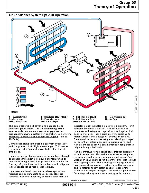
Air Conditioner System Cycle Of Operation
Group 15: Diagnostic Information
Diagnose Air Conditioning System Malfunctions
Diagnose Heater System Malfunctions
Group 25: Test
Proper Refrigerant Handling
R134a Refrigerant Cautions
R134a Oil Charge Capacity
R134a Refrigerant Charge Capacity
Refrigerant Hoses And Tubing Inspection
Operating Pressure Diagnostic Chart
Air Conditioner Low Pressure Switch Test (S.N. —102598)
Air Conditioner High Pressure Switch Test (S.N. —102598)
Air Conditioner High/Low Pressure (Binary) Switch Test (S.N. 102599— )
Freeze Control Switch Test
Leak Testing
John Deere Crawler Dozers 450J, 550J, 650J Operation and Test Service Manual (TM2257)
![]()