
John Deere Crawler Dozers 550K, 650K Operation and Tests Service Manual (TM12288)
Complete Operation and Tests manual with Electrical Wiring Diagrams for John Deere 550K, 650K Crawler Dozer, with workshop information to maintain, diagnose, and rebuild like professional mechanics.
John Deere Crawler Dozers 550K, 650K workshop Operation and Tests manual includes:
* Numbered table of contents easy to use so that you can find the information you need fast.
* Detailed sub-steps expand on repair procedure information
* Numbered instructions guide you through every repair procedure step by step.
* Troubleshooting and electrical service procedures are combined with detailed wiring diagrams for ease of use.
* Notes, cautions and warnings throughout each chapter pinpoint critical information.
* Bold figure number help you quickly match illustrations with instructions.
* Detailed illustrations, drawings and photos guide you through every procedure.
* Enlarged inset helps you identify and examine parts in detail.
TM12288 - John Deere 550K, 650K Crawler Dozer Technical Manual - Operation and Tests.PDF
TM12288 - John Deere 550K, 650K Crawler Dozer Technical Manual - Operation and Tests.EPUB
Total Pages: 1,544 pages
File Format: PDF/EPUB/MOBI/AZW (PC/Mac/Android/Kindle/iPhone/iPad; bookmarked, ToC, Searchable, Printable)
Language: English
TABLE OF CONTENTS
550K (PIN: 1T0550KX**E217276-275527)
650K (PIN: 1T0650KX**E216396-275533)
MAIN SECTIONS
Foreword
General Information
Safety
Diagnostic Trouble Codes (DTCs)
Engine Control Unit (ECU) Diagnostic Trouble Codes
Standard Display Monitor (SDM) Diagnostic Trouble Codes
Sealed Switch Module (SSM) Diagnostic Trouble Codes
Vehicle Control Unit (VCU) Diagnostic Trouble Codes
Blade Control Joystick (BCJ) Diagnostic Trouble Codes
Electrohydraulic Controller (EHC) Diagnostic Trouble Codes
Operational Checkout Procedure
Operational Checkout Procedure
Engine
Theory Of Operation
Diagnostic Information
Adjustments
Tests
Electrical System
System Information
System Diagrams
Sub-System Diagnostics
Monitor Operation
Topcon Integrated Grade Control (IGC) Operation (Factory Installation)
References
Hydraulic System
Theory of Operation
Diagnostic Information
Adjustments
Tests
Hydrostatic System
Theory of Operation
Diagnostic Information
Test
Heating and Air Conditioning
Theory of Operation
Diagnostic Information
Test
tm12288 - 550K and 650K Crawler Dozer
Table of Contents
Foreword
Section 9000: General Information
Group 01: Safety
Recognize Safety Information
Follow Safety Instructions
Operate Only If Qualified
Wear Protective Equipment
Avoid Unauthorized Machine Modifications
Inspect Machine
Stay Clear of Moving Parts
Avoid High-Pressure Fluids
Avoid High-Pressure Oils
Beware of Exhaust Fumes
Prevent Fires
Prevent Battery Explosions
Handle Chemical Products Safely
Dispose of Waste Properly
Prepare for Emergencies
Add Cab Guarding For Special Uses
Start Only From Operator’s Seat
Prevent Unintended Machine Movement
Avoid Work Site Hazards
Keep Riders Off Machine
Avoid Backover Accidents
Avoid Machine Tip Over
Prevent Unintended Detonation of Explosive Devices
Park And Prepare For Service Safely
Service Cooling System Safely
Remove Paint Before Welding or Heating
Make Welding Repairs Safely
Drive Metal Pins Safely
Section 9001: Diagnostic Trouble Codes (DTCs)
Group 10: Engine Control Unit (ECU) Diagnostic Trouble Codes
Engine Control Unit (ECU) Diagnostic Trouble Codes
000091.09 - CAN Throttle Missing From VCU
000111.07 - Engine Coolant Level Invalid
000111.17 - Engine Coolant Temperature Invalid
000647.05 - Fan Drive Solenoid Open or Short to Power
000647.06 - Fan Drive Solenoid Short to Ground
001321.09 - Starter Signal Missing
001321.16 - Engine Starter Engaged Too Long
001321.31 - Starter Solenoid Open Circuit
002000.13 - Security Violation
002030.19 - Communication Error With Source Address 30
003353.31 - Alternator Excitation Condition Exists
005484.05 - Fan Reversing Solenoid Open or Short to Power
005484.06 - Fan Reversing Solenoid Short to Ground
Group 20: Standard Display Monitor (SDM) Diagnostic Trouble Codes
Standard Display Monitor (SDM) Diagnostic Trouble Codes
000096.03 - Fuel Level Sensor Open or Short
000096.04 - Fuel Level Sensor Short to Ground
002000.09 - CAN Communication No ECU Configuration
002030.09 - Loss of CAN Communication With VCU
002141.09 - Loss of CAN Communication With SSM
002251.09 - Communication System Message Missing
003156.09 - Loss of CAN Communication With EHC
Group 30: Sealed Switch Module (SSM) Diagnostic Trouble Codes
Sealed Switch Module (SSM) Diagnostic Trouble Codes
000444.04 - Invalid Application Configuration
000629.12 - JDOS Watchdog Timeout
000639.12 - Lost CAN Message
000639.14 - CAN Bus Off
002033.09 - No CAN Messages
002634.04 - Ignition Relay Short to Ground
002634.05 - Ignition Relay Open Circuit
520752.04 - Keypad 7 Button Stuck
520752.09 - No LED Response For Keypad 7 Button
520753.04 - Washer Button Stuck
520753.09 - No LED Response For Washer Button
520754.04 - Keypad 9 Button Stuck
520754.09 - No LED Response for Keypad 9 Button
520755.04 - Transmission Speed Up Button Stuck
520755.09 - No LED Response For Transmission Speed Up Button
523335.04 - Transmission Speed Down Button Stuck
523335.09 - No LED Response For Transmission Speed Down Button
523336.04 - Rear Wiper Button Stuck
523336.09 - No LED Response For Rear Wiper Button
523338.04 - Front Wiper Button Stuck
523338.09 - No LED Response For Front Wiper Button
523339.04 - Wiper Speed Button Stuck
523339.09 - No LED Response For Wiper Speed Button
523340.04 - Standard Lights Button Stuck
523340.09 - No LED Response For Standard Lights Button
523849.04 - Work Lights Button Stuck
523849.09 - No LED Response For Work Lights Button
523850.04 - Boom-Height Kickout Button Stuck
523850.09 - No LED Response For Boom-Height Kickout Button
523852.04 - Keypad 6 Button Stuck
523852.09 - No LED Response For Keypad 6 Button
523854.04 - Keypad 5 Button Stuck
523854.09 - No LED Response For Keypad 5 Button
523855.04 - Keypad 4 Button Stuck
523855.09 - No LED Response For Keypad 4 Button
523856.04 - Auxiliary Power Button Stuck
523856.09 - No LED Response For Auxiliary Power Button
523857.04 - Return To Dig Button Stuck
523857.09 - No LED Response For Return To Dig Button
523858.04 - Keypad 3 Button Stuck
523858.09 - No LED Response For Keypad 3 Button
523860.04 - Keypad 2 Button Stuck
523860.09 - No LED Response For Keypad 2 Button
523861.04 - Auto-Off Button Stuck
523861.09 - No LED Response For Auto-Off Button
523862.04 - Reversing Fan Button Stuck
523862.09 - No LED Response For Reversing Fan Button
523863.04 - Hydraulic Enable Button Stuck
523863.09 - No LED Response For Hydraulic Enable Button
523864.04 - Undefined Button 4 Stuck
523864.09 - No LED Response For Undefined Button 4
523865.04 - Undefined Button 3 Stuck
523865.09 - No LED Response For Undefined Button 3
523867.04 - Stop Button Stuck
523867.09 - No LED Response For Stop Button
523868.04 - Start Button Stuck
523868.09 - No LED Response For Start Button
Group 40: Vehicle Control Unit (VCU) Diagnostic Trouble Codes
Vehicle Control Unit (VCU) Diagnostic Trouble Codes
000070.00 - Park Lock Lever Inputs Both ON
000070.01 - Park Lock Lever Inputs Both OFF
000091.03 - Throttle Sensor Short to Power
000091.04 - Throttle Sensor Open or Short
000116.00 - Brake Pressure High
000116.01 - Brake Pressure Low
000116.03 - Brake Pressure Short to Power
000116.04 - Brake Pressure Open or Short
000158.03 - Switched System Volts Too High
000158.04 - Switched System Volts Too Low
000168.04 - Unswitched System Volts Too Low
000177.00 - Trans Oil Temp Overtemp
000177.03 - Trans Oil Temp Short to Power
000177.04 - Trans Oil Temp Short to Ground
000177.16 - Trans Oil Temp Mod Overtemp
000190.09 - CAN Comm No Engine Speed
000190.19 - CAN Engine Speed Message Invalid Data
000521.00 - Decel Sensor Input > Max Cal
000521.01 - Decel Sensor Input < Min Cal
000521.03 - Decel Sensor Short to Power
000521.04 - Decel Sensor Open or Short
000521.05 - Decel Sensor Brake Cal Too Lo
000521.06 - Decel Sensor Brake Cal Too Hi
000521.13 - Decel Sensor Not Calibrated
000521.15 - Decel Sensor Min Cal Too High
000521.16 - Decel Sensor Max Cal Too High
000521.17 - Decel Sensor Min Cal Too Low
000521.18 - Decel Sensor Max Cal Too Low
000581.00 - Speed Buttons Input > Max Cal
000581.01 - Speed Buttons Input < Min Cal
000581.03 - Speed Buttons Short to Power
000581.04 - Speed Buttons Open or Short
000581.07 - Speed Buttons Stuck Button
000581.13 - Speed Buttons Not Calibrated
000581.15 - Speed Buttons Min Cal Too High
000581.16 - Speed Buttons Max Cal Too High
000581.17 - Speed Buttons Min Cal Too Low
000581.18 - Speed Buttons Max Cal Too Low
000604.03 - FNR Neutral Switch Open Circuit
000604.04 - FNR Neutral Switch Short Circuit
000604.15 - FNR Neut Switch Min Cal Too High
000604.16 - FNR Neut Switch Max Cal Too High
000604.17 - FNR Neut Switch Min Cal Too Low
000604.18 - FNR Neut Switch Max Cal Too Low
000619.05 - Brake Solenoid Open or Short to Power
000619.06 - Brake Solenoid Short to Ground
000629.12 - VCU Watchdog Timer Exceeded
000907.04 - Left Speed Sensor Short to Ground
000907.07 - Left Speed Sensor No Response
000907.12 - Left Speed Sensor Open
000908.04 - Right Speed Sensor Short to Ground
000908.07 - Right Speed Sensor No Response
000908.12 - Right Speed Sensor Open
000924.06 - Aux Power Short to Ground
001569.31 - Engine Derate Condition
001638.00 - Hyd Oil Temp Overtemp
001638.03 - Hyd Oil Temp Short to Power
001638.04 - Hyd Oil Temp Short to Gnd
001638.16 - Hyd Oil Temp Mod Overtemp
001713.31 - Hyd Oil Filter Restricted
002000.09 - Loss of CAN comm with ECU
002023.09 - Loss of CAN Comm with SDM
002141.09 - Loss of CAN Comm with SSM
002251.09 - Communication System Message Missing
002355.05 - Front Work Light Open or Short to Power
002355.06 - Front Work Light Short to Ground
002356.05 - Front Drive Light Open or Short to Power
002356.06 - Front Drive Light Short to Ground
002359.05 - Rear Drive Light Open or Short to Power
002359.06 - Rear Drive Light Short to Ground
002660.00 - Steer Sensor Input > Max Cal
002660.01 - Steer Sensor Input < Min Cal
002660.03 - Steer Sensor Short to Power
002660.04 - Steer Sensor Open or Short
002660.07 - Steer Sensor Neut Cal Out of Range
002660.13 - Steer Sensor Not Calibrated
002660.15 - Steer Sensor Min Cal Too High
002660.16 - Steer Sensor Max Cal Too High
002660.17 - Steer Sensor Min Cal Too Low
002660.18 - Steer Sensor Max Cal Too Low
002661.00 - FNR Sensor Input > Max Cal
002661.01 - FNR Sensor Input < Min Cal
002661.03 - FNR Sensor Short to Power
002661.04 - FNR Sensor Open or Short
002661.07 - FNR Sensor Neut Cal Out of Range
002661.13 - FNR Sensor Not Calibrated
002661.15 - FNR Sensor Min Cal Too High
002661.16 - FNR Sensor Max Cal Too High
002661.17 - FNR Sensor Min Cal Too Low
002661.18 - FNR Sensor Max Cal Too Low
003359.31 - Trans Oil Filter Restricted
003509.03 - 5V Supply #1 Short to Power
003509.04 - 5V Supply #1 Short to Ground
003511.03 - 5V Supply #3 Short to Power
003511.04 - 5V Supply #3 Short to Ground
003512.03 - 5V Supply #4 Short to Power
003512.04 - 5V Supply #4 Short to Ground
521996.06 - Door Washer Motor Short to Ground
521997.05 - Left Door Wiper Open or Short to Power
521997.06 - Left Door Wiper Short to Ground
521998.05 - Right Door Wiper Open or Short to Power
521998.06 - Right Door Wiper Short to Ground
521999.00 - Park Lock Lever Inputs Both On
521999.01 - Park Lock Lever Inputs Both Off
522312.06 - Washer Motor Short to Ground
522433.05 - Rear Wiper Open or Short to Power
522433.06 - Rear Wiper Short to Ground
522434.05 - Front Wiper Open or Short to Power
522434.06 - Front Wiper Short to Ground
522444.00 - Charge Pressure High
522444.01 - Charge Pressure Low
522444.03 - Charge Pressure Short to Power
522444.04 - Charge Pressure Open or Short
522447.05 - Right Fwd Pump Coil Open or Short
522447.06 - Right Fwd Pump Coil Short to Power
522447.15 - Right Fwd Pump Thresh Cal High
522447.16 - Right Fwd Pump Max Spd Cal High
522447.17 - Right Fwd Pump Thresh Cal Low
522447.18 - Right Fwd Pump Max Spd Cal Low
522448.05 - Right Rev Pump Coil Open or Short
522448.06 - Right Rev Pump Coil Short to Pwer
522448.15 - Right Rev Pump Thresh Cal High
522448.16 - Right Rev Pump Max Spd Cal High
522448.17 - Right Rev Pump Thresh Cal Low
522448.18 - Right Rev Pump Max Spd Cal Low
522449.05 - Left Rev Pump Coil Open or Short
522449.06 - Left Rev Pump Coil Short to Power
522449.15 - Left Rev Pump Thresh Cal High
522449.16 - Left Rev Pump Max Spd Cal High
522449.17 - Left Rev Pump Thresh Cal Low
522449.18 - Left Rev Pump Max Spd Cal Low
522450.05 - Left Fwd Pump Coil Open or Short
522450.06 - Left Fwd Pump Coil Short to Power
522450.15 - Left Fwd Pump Thresh Cal High
522450.16 - Left Fwd Pump Max Spd Cal High
522450.17 - Left Fwd Pump Thresh Cal Low
522450.18 - Left Fwd Pump Max Spd Cal Low
523108.13 - Pump/Motor Not Calibrated
523108.14 - VCU Not Calibrated
523577.05 - Left Motor Sol Open or Short
523577.06 - Left Motor Sol Short to Power
523577.13 - Motor High Speed Not Calibrated
523577.16 - Left Motor Max Cal Too High
523577.18 - Left Motor Max Cal Too Low
523578.05 - Right Motor Sol Open or Short
523578.06 - Right Motor Sol Short to Power
523578.16 - Right Motor Max Cal Too High
523578.18 - Right Motor Max Cal Too Low
524233.07 - Hydrostatic Drive System Not Responding
Group 50: Blade Control Joystick (BCJ) Diagnostic Trouble Codes
Blade Control Joystick (BCJ) Diagnostic Trouble Codes
002697.03 - X-Axis Sensor Out of Range High
002697.04 - X-Axis Sensor Out of Range Low
002697.12 - X-Axis Joystick Internal Failure
002697.13 - X-Axis Joystick Setup Failure
002697.14 - X-Axis Joystick Sensor Failure
002698.03 - Y-Axis Sensor Out of Range High
002698.04 - Y-Axis Sensor Out of Range Low
002698.12 - Y-Axis Joystick Internal Failure
002698.13 - Y-Axis Joystick Setup Failure
002698.14 - Y-Axis Joystick Sensor Failure
Group 60: Electrohydraulic Controller (EHC) Diagnostic Trouble Codes
Electrohydraulic Controller (EHC) Diagnostic Trouble Codes
000158.03 - EHC System Volts Too High
000158.04 - EHC System Volts Too Low
000620.03 - Sensor Short to Power
000620.04 - Sensor Short to Ground
001903.00 - Auxiliary 1 PVE Open Circuit
001903.01 - Auxiliary 1 PVE Low or Open Circuit
001903.03 - Auxiliary 1 PVE Short to Power
001903.04 - Auxiliary 1 PVE Short to Ground
001903.31 - Auxiliary 1 PVE Spool Position Error
001915.00 - Auxiliary 2 PVE Open Circuit
001915.01 - Auxiliary 2 PVE Low or Open Circuit
001915.03 - Auxiliary 2 PVE Short to Power
001915.04 - Auxiliary 2 PVE Short to Gound
001915.31 - Auxiliary 2 PVE Spool Position Error
002697.09 - CAN Joystick Position Missing From BCJ
002712.00 - Hydraulic Enable Sw Inputs Both On
002712.01 - Hydraulic Enable Sw Inputs Both Off
003157.03 - Increment/Decrement Buttons Short to Power
003157.04 - Increment/Decrement Buttons Open or Short
003157.31 - Increment/Decrement Buttons Invalid Output
522442.03 - Blade Button Short to Power
522442.04 - Blade Buttons Open or Short
522442.31 - Blade Buttons Invalid Output
523779.00 - Blade Rotate Current Above Maximum
523779.01 - Blade Rotate Current Below Minimum
523780.00 - Tilt PVE Open Circuit
523780.01 - Tilt PVE Low or Open Circuit
523780.03 - Tilt PVE Short to Power
523780.04 - Tilt PVE Short to Ground
523780.31 - Tilt PVE Spool Position Error
523781.00 - Height PVE Open Circuit
523781.01 - Height PVE Low or Open Circuit
523781.03 - Height PVE Short to Power
523781.04 - Height PVE Short to Ground
523781.31 - Height PVE Spool Position Error
524059.00 - Auxiliary 2 Joystick Sensor 2 Volts High
524059.01 - Auxiliary 2 Joystick Sensor 2 Volts Low
524059.03 - Auxiliary 2 Joystick Sensor 2 Short to Power
524059.04 - Auxiliary 2 Joystick Sensor 2 Short to Ground
524059.31 - Auxiliary 2 Joystick Sensor 2 Invalid Output
524062.00 - Auxiliary 1 Joystick Sensor 2 Volts High
524062.01 - Auxiliary 1 Joystick Sensor 2 Volts Low
524062.03 - Auxiliary 1 Joystick Sensor 2 Short to Power
524062.04 - Auxiliary 1 Joystick Sensor 2 Short to Ground
524062.31 - Auxiliary 1 Joystick Sensor 2 Invalid Output
524085.00 - Auxiliary 2 Joystick Sensor 1 Volts High
524085.01 - Auxiliary 2 Joystick Sensor 1 Volts Low
524085.03 - Auxiliary 2 Joystick Sensor 1 Short to Power
524085.04 - Auxiliary 2 Joystick Sensor 1 Short to Ground
524085.14 - Auxiliary 2 Joystick Sensor Mismatch
524085.31 - Auxiliary 2 Joystick Sensor 1 Invalid Output
524086.00 - Auxiliary 1 Joystick Sensor 1 Volts High
524086.01 - Auxiliary 1 Joystick Sensor 1 Volts Low
524086.03 - Auxiliary 1 Joystick Sensor 1 Short to Power
524086.04 - Auxiliary 1 Joystick Sensor 1 Short to Ground
524086.14 - Auxiliary 1 Joystick Sensor Mismatch
524086.31 - Auxiliary 1 Joystick Sensor 1 Invalid Output
Section 9005: Operational Checkout Procedure
Group 10: Operational Checkout Procedure
Operational Checkout
Section 9010: Engine
Group 05: Theory Of Operation
John Deere Engine
Cold Start Aid System Theory of Operation—If Equipped
Group 15: Diagnostic Information
John Deere Engine
Engine Cooling System Component Location
Engine Fuel System Component Location
Engine Intake and Exhaust Component Location
Group 20: Adjustments
John Deere Engine
Service Filter Cleaning
Group 25: Tests
John Deere Engine
Fluid Sampling Procedure—If Equipped
Low-Pressure Fuel Pump Pressure Test
Engine Idle Speeds and Auto Shutdown Check
Exhaust Emissions Test Point
Section 9015: Electrical System
Group 05: System Information
Electrical Diagram Information
Electrical Schematic Symbols
Group 10: System Diagrams
Fuse and Relay Specifications
System Functional Schematic, Wiring Diagram, and Component Location Legend
System Functional Schematic and Section Legend
System Functional Schematic and Section Legend—Integrated Grade Control (IGC)
JDLink™ Functional Schematic
Engine Interface Harness (W10) Component Location
Engine Interface Harness (W10) Wiring Diagram
Vehicle Harness (W11) Component Location
Vehicle Harness (W11) Wiring Diagram
Vehicle (IGC Controls) Harness (W12) Component Location
Vehicle (IGC Controls) Harness (W12) Wiring Diagram
Grille Harness (W13) Component Location
Grille Harness (W13) Wiring Diagram
Cooling Package Harness (W14) Component Location
Cooling Package Harness (W14) Wiring Diagram
Fan Compartment Harness (W18) Component Location
Fan Compartment Harness (W18) Wiring Diagram
Front Vehicle Harness (W19) Component Location
Front Vehicle Harness (W19) Wiring Diagram
Front Vehicle (IGC Controls) Harness (W20) Component Location
Front Vehicle (IGC Controls) Harness (W20) Wiring Diagram
Fuel Tank Harness (W21) Component Location
Fuel Tank Harness (W21) Wiring Diagram
Load Center Harness (W22) Component Location
Load Center Harness (W22) Wiring Diagram
Operator’s Station Harness (W23) Component Location
Operator’s Station Harness (W23) Wiring Diagram
Operator’s Station (IGC Controls) Harness (W24) Component Location
Operator’s Station (IGC Controls) Harness (W24) Wiring Diagram
Front Dash Harness (W25) Component Location
Front Dash Harness (W25) Wiring Diagram
Left Console Harness (W26) Component Location
Left Console Harness (W26) Wiring Diagram
Under Seat Heater Harness (W27) Component Location
Under Seat Heater Harness (W27) Wiring Diagram
Power Outlet Harness (W28) Component Location
Power Outlet Harness (W28) Wiring Diagram
Cab Roof Harness (W29) Component Location
Cab Roof Harness (W29) Wiring Diagram
Canopy Roof Harness (W30) Component Location
Canopy Roof Harness (W30) Wiring Diagram
Heater and Air Conditioner Harness (W31) Component Location
Heater and Air Conditioner Harness (W31) Wiring Diagram
Condenser Harness (W32) Component Location
Condenser Harness (W32) Wiring Diagram
Dome Light Harness (W33) Component Location
Dome Light Harness (W33) Wiring Diagram
Radio Harness (W34) Component Location
Radio Harness (W34) Wiring Diagram
Engine Harness (W35) Component Location
Engine Harness (W35) Wiring Diagram
Low-Pressure Fuel Pump Harness (W37) Component Location
Low-Pressure Fuel Pump Harness (W37) Wiring Diagram
Fuel Injector Harness (W38) Component Location
Fuel Injector Harness (W38) Wiring Diagram
Glow Plug Harnesses (W39 and W40) Component Location
Glow Plug Harnesses (W39 and W40) Wiring Diagrams
JDLink™ Harnesses (W6002 and W6003) Component Location
Modular Telematics Gateway (MTG) Harness (W6002) Wiring Diagram
Satellite (SAT) Harness (W6003) Wiring Diagram
Group 15: Sub-System Diagnostics
Starting and Charging Circuit Theory of Operation
Park Brake Circuit Theory of Operation
Controller Area Network (CAN) Circuit Theory of Operation
Engine Control Unit (ECU) Circuit Theory of Operation
Standard Display Monitor (SDM) Circuit Theory of Operation
Vehicle Control Unit (VCU) Circuit Theory of Operation
Hydraulic System Circuit Theory of Operation
Hydrostatic System Circuit Theory of Operation
Wiper and Washer Circuits Theory of Operation
Horn, Auxiliary Power, and Lighting Circuits Theory of Operation
Air Conditioner and Heater Circuits Theory of Operation
Seat Heater and Air Seat Motor Circuits Theory of Operation
Integrated Grade Control (IGC) Circuit Theory of Operation—If Equipped
JDLink™ Circuit Theory of Operation—If Equipped
Exhaust Aftertreatment Circuit Theory of Operation
Group 16: Monitor Operation
Standard Display Monitor (SDM)—Service Mode
Standard Display Monitor (SDM)—Codes
Standard Display Monitor (SDM)—Exhaust Filter
Standard Display Monitor (SDM)—Service
Standard Display Monitor (SDM)—Machine Settings
Standard Display Monitor (SDM)—Diagnostics
Standard Display Monitor (SDM)—Monitor
Standard Display Monitor (SDM)—Calibrate
Standard Display Monitor (SDM)—Vehicle Control Unit (VCU) Diagnostics
Standard Display Monitor (SDM)—Software Delivery
Group 17: Topcon® Integrated Grade Control (IGC) Operation (Factory Installation)
Topcon® Integrated Grade Control (IGC) Circuit Schematic (Factory Installation)
Topcon® Integrated Grade Control (IGC) Circuit Theory of Operation (Factory Installation)
IGC Controller/Receiver Harnesses (W41 and W42) Component Location
IGC Controller/Receiver Harness 1 (W41) Wiring Diagram
IGC Controller/Receiver Harness 2 (W42) Wiring Diagram
IGC Display Unit Harness (W43) Component Location
IGC Display Unit Harness (W43) Wiring Diagram
IGC Grille Harness (W44) Component Location
IGC Grille Harness (W44) Wiring Diagram
Group 20: References
Service ADVISOR™ Diagnostic Application
Service ADVISOR™ Connection Procedure
Reading Diagnostic Trouble Codes with Service ADVISOR™ Diagnostic Application
JDLink™ Connection Procedure
Alternator Test Procedure
CAN Circuit Test
Electrical Component Specifications
Vehicle Control Unit (VCU) Calibration
Integrated Grade Control (IGC) Checks—If Equipped
Integrated Grade Control (IGC) Diagnose Malfunctions—If Equipped
Wire Harness Test
Decelerator/Brake Pedal Adjustment
Engine Speed Control Remove and Install
Rotary Sensor Remove and Install
Exhaust Filter Sensor Installation
Transmission Control Lever (TCL) Adjustment
Controller Remove and Install
Intermittent Diagnostic Trouble Code (DTC) Diagnostics
Replace Weather Pack™ Connector
Install Weather Pack™ Contact
Replace DEUTSCH® Connectors
Replace DEUTSCH DEUTSCH is a trademark of Deutsch Co. Rectangular or Triangular Connectors
Install DEUTSCH® Contact
Replace CINCH CINCH is a trademark of the Cinch Co. Connectors
Install CINCH CINCH is a trademark of the Cinch Co. Contact
Repair 32 and 48 Way CINCH CINCH is a trademark of the Cinch Co. Connectors
Replace (Pull Type) Metri-Pack™ Connectors
Replace (Push Type) Metri-Pack™ Connectors
Section 9025: Hydraulic System
Group 05: Theory of Operation
Hydraulic System Operation
Hydraulic Pump Operation
Hydraulic Pump and Reservoir Operation
Hydraulic Control Valve Operation
Hydraulic Control Valve Operation—Integrated Grade Control (IGC)
Hydraulic System Relief Valve Operation
Hydraulic Cylinder Operation
Hydraulic Filter Operation
Hydraulic Reversing Fan Drive Operation
Hydraulic Non-Reversing Fan Drive Operation
Ripper Operation
Winch Operation
Group 15: Diagnostic Information
Hydraulic System Schematic
Hydraulic System Schematic—Integrated Grade Control (IGC)
Hydraulic System Line Identification
Hydraulic System Line Identification—Integrated Grade Control (IGC)
Hydraulic System Component Location
Hydraulic System Component Location—Integrated Grade Control (IGC)
Ripper Hydraulic Component Location
Winch Hydraulic Component Location
Hydraulic System Diagnose Malfunctions
Hydraulic System Diagnose Malfunctions—Integrated Grade Control (IGC)
Hydraulic Fan Does Not Reach Full Speed
Hydraulic Fan Runs at Full Speed Only
Hydraulic Fan Does Not Spin
Hydraulic Fan Will Not Reverse Direction
Group 20: Adjustments
Blade Pitch Linkage Adjustment
Blade Control Lever Linkage Adjustment
Auxiliary Hydraulic Control Lever Linkage Adjustment
Group 25: Tests
JT02156A Digital Pressure and Temperature Analyzer Kit Installation
Ultra Clean® Hand Launcher
Hydraulic Oil Warm-Up Procedure
Hydraulic Oil Sampling Procedure—If Equipped
Hydraulic Pump Flow Test
Hydraulic System Relief Valve Test
Hydraulic System Relief Valve Test—Integrated Grade Control (IGC)
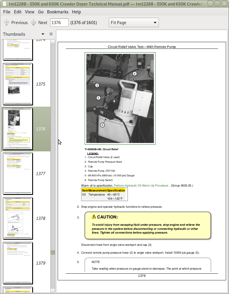
Circuit Relief Valve Test—With Remote Pump
Lift Cylinder Drift Test
Cylinder Leakage Test
Fan Pump Flow Test
Fan Motor Speed Test
Fan Motor Case Drain Test
Section 9026: Hydrostatic System
Group 05: Theory of Operation
Hydrostatic System Operation
Transmission Control Circuit Operation (Flow Chart)
Charge Pump Operation
Hydrostatic Charge Oil Filter Operation
Neutral Charge Relief Valve Operation
Park Brake Valve Operation
Multi-Function Valve Operation
Hydrostatic Thermal Bypass Valve Operation
Pump Pressure Control Pilot (PCP) Operation
Pump Displacement Control Valve (PDCV) Operation
Hydrostatic Pump Operation
Flushing Valve and Operating Charge Relief Valve Operation
Hydrostatic Motor Operation
Group 15: Diagnostic Information
Hydrostatic System Schematic
Hydrostatic System Line Identification
Hydrostatic System Component Location
Hydrostatic System Diagram—Neutral with Park Brake On
Hydrostatic System Diagram—Forward (Slow Speed)
Hydrostatic System Diagram—Reverse (Fast Speed)
Overheating Malfunctions
High/Low Charge Pressure Malfunctions
Mistrack/Index Malfunctions
Machine Full Speed Malfunctions
Low Power Malfunctions
Track Malfunctions
VCU Calibration Malfunctions
Group 25: Test
Transmission Oil Warm-Up Procedure
Hydrostatic Oil Sampling Procedure—If Equipped
Releasing Park Brake to Tow the Machine
Hydrostatic Pump Flushing Procedure
Pressure Control Pilot (PCP) Manual Override Test
Pressure Control Pilot (PCP) Test
Pressure Control Pilot (PCP) Internal Adjustment
Multi-Function Relief Valve Test
Transmission Efficiency Test
Neutral Charge Relief and Operating Charge Relief Pressure Test
Pump Displacement Control Valve (PDCV) Neutral (Null) Adjustment
Pump Servo Pressure Test
Hydrostatic Motor Min.-Max. Angle Servo Piston Pressure Test
Hydrostatic Motor Minimum Angle Stop Adjustment
Charge Pump Flow Test
Charge Pressure Sensor Test
Hydrostatic Thermal Bypass Valve Test
Section 9031: Heating and Air Conditioning
Group 05: Theory of Operation
Air Conditioning System Cycle Of Operation
Group 15: Diagnostic Information
Air Conditioner and Heater Component Location
Diagnose Air Conditioning System Malfunctions
Air Conditioning System Does Not Operate
Air Conditioner Does Not Cool Interior of Cab
Air Conditioner Runs Constantly, Too Cold
Diagnose Heater System Malfunctions
Heater System Does Not Operate
Heater Does Not Warm Interior of Cab
Interior Windows Continue to Fog
Group 25: Test
Refrigerant Cautions and Proper Handling
R134a Refrigerant Cautions
R134a Oil Charge Capacity
R134a Refrigerant Charge Capacity
Air Conditioner and Heater Operational Checks
Refrigerant Leak Test
Air Conditioner Compressor Clutch Test
Air Conditioner High/Low Pressure Switch Test
Air Conditioner Freeze Control Switch Test
R134a Air Conditioning System Test
Operating Pressure Diagnostic Chart
John Deere Crawler Dozers 550K, 650K Operation and Tests Service Manual (TM12288)
![]()