
John Deere Crawler Dozers 550K, 650K Repair Service Manual (TM13357X19)
Complete service repair manual for John Deere 550K, 650K Crawler Dozer (S.N. from 275977), with all the shop information to maintain, repair, and rebuild like professional mechanics.
John Deere Crawler Dozers 550K, 650K workshop service & repair manual includes:
* Numbered table of contents easy to use so that you can find the information you need fast.
* Detailed sub-steps expand on repair procedure information
* Numbered instructions guide you through every repair procedure step by step.
* Notes, cautions and warnings throughout each chapter pinpoint critical information.
* Bold figure number help you quickly match illustrations with instructions.
* Detailed illustrations, drawings and photos guide you through every procedure.
* Enlarged inset helps you identify and examine parts in detail.
TM13357X19 - John Deere 550K, 650K Crawler Dozer Technical Manual - Repair.PDF
TM13357X19 - John Deere 550K, 650K Crawler Dozer Technical Manual - Repair.EPUB
Total Pages: 813 pages
File Format: PDF/EPUB/MOBI/AZW (PC/Mac/Android/Kindle/iPhone/iPad; bookmarked, ToC, Searchable, Printable)
Language: English
650K ( PIN: 1T0650KX_ _F275978-303837)
550K (PIN: 1T0550KX_ _F275977-303907)
MAIN SECTIONS
Foreword
General Information
Safety
Torque Values
Tracks
Track System
Axles and Suspension Systems
Drive Axle Housing and Support
Axle Shaft, Bearings, and Reduction Gears
Transmission
Removal and Installation
Controls Linkage
Input Drive Shafts and U-Joints
Hydrostatic System
Engine
Removal and Installation
Engine Auxiliary System
Cold Weather Starting Aids
Cooling Systems
Intake System
External Exhaust Systems
External Fuel Supply Systems
Park Brake
Removal and Installation
Controls Linkage
Hydraulic System
Equipment Attaching
Drawbar
Electrical System
Removal and Installation
Frame, Chassis, or Supporting Structure
Frame Installation
Frame Bottom Guards
Chassis Weights
Operator`s Station
Removal and Installation
Operator Enclosure
Seat and Seat Belt
Heating and Air Conditioning
Sheet Metal and Styling
Hood or Engine Enclosure
Grille and Grille Housing
Safety, Convenience, and Miscellaneous
Horn and Warning Devices
Main Hydraulic System
Hydraulic System
Bulldozer
Blades
Control Linkage
Frames
Hydraulic System
Ground Conditioning Tool
Ripper
Blades, Teeth, and Shanks
Hydraulic System
Dealer Fabricated Tools
tm13357x19 - 550K and 650K Crawler Dozer - Table of Contents
Foreword
Manual Identification—READ THIS FIRST!
Section 00: General Information
Group 0001: Safety
Recognize Safety Information
Follow Safety Instructions
Operate Only If Qualified
Wear Protective Equipment
Avoid Unauthorized Machine Modifications
Inspect Machine
Stay Clear of Moving Parts
Avoid High-Pressure Fluids
Avoid High-Pressure Oils
Work In Ventilated Area
Prevent Fires
Prevent Battery Explosions
Handle Chemical Products Safely
Decommissioning — Proper Recycling and Disposal of Fluids and Components
Exhaust Filter Ash Handling and Disposal
Prepare for Emergencies
Add Cab Guarding for Special Uses
Clean Debris from Machine
Use Steps and Handholds Correctly
Start Only From Operator's Seat
Use and Maintain Seat Belt
Prevent Unintended Machine Movement
Avoid Work Site Hazards
Keep Riders Off Machine
Avoid Backover Accidents
Avoid Machine Tip Over and Machine Damage
Operating or Traveling On Public Roads
Inspect and Maintain ROPS
Add and Operate Attachments Safely
Park and Prepare for Service Safely
Service Cooling System Safely
Remove Paint Before Welding or Heating
Make Welding Repairs Safely
Drive Metal Pins Safely
Clean Exhaust Filter Safely
Group 0003: Torque Values
Additional Metric Cap Screw Torque Values
Inch Series Four Bolt Flange Fitting for High-Pressure Service Recommendations
Metric 24° O-Ring Seal DIN 20078 Service Recommendations
Metric Bolt and Cap Screw Torque Values
O-Ring Boss Fittings in Aluminum Housing Service Recommendations—Excavators
O-Ring Face Seal Fittings With Metric Hex Nut and Stud End for High-Pressure Service Recommendations
O-Ring Face Seal Fittings With Metric Hex Nut and Stud End for Standard Pressure Service Recommendations
O-Ring Face Seal Fittings With SAE Inch Hex Nut and Stud End for High-Pressure Service Recommendations
Service Recommendations for 37° Flare and 30° Cone Seat Connectors
Service Recommendations for Flared Connections—Straight or Tapered Threads
Service Recommendations for Flat Face O-Ring Seal Fittings
Service Recommendations For Inch Series Four Bolt Flange Fittings
Service Recommendations for Metric Series Four Bolt Flange Fitting
Service Recommendations For Non-Restricted Banjo (Adjustable) Fittings
Service Recommendations for O-Ring Boss Fittings
Service Recommendations For O-Ring Boss Fittings With Shoulder
Unified Inch Bolt and Cap Screw Torque Values
Section 01: Tracks
Group 0130: Track System
Welding On Machine
Track Guides and Rock Guards Remove and Install
Carrier Roller Wear Inspection
Carrier Roller Remove and Install
Carrier Roller Disassemble and Assemble
Metal Face Seals Inspection
Carrier Roller Leakage Test
Track Roller Wear Inspection
Track Roller Remove and Install
Track Roller Disassemble and Assemble
Track Roller Leakage Test
Track Shoe Grouser Wear Inspection
Track Shoe Remove and Install
Track Link Height Inspection
Bushing Outside Diameter for Lubricated Track Chain Inspection
Track Pitch for Lubricated Track Chain Inspection
Lubricated Track Chain Remove and Install
Lubricated Track Chain to Turn Bushings and Lubricate Chain Disassemble and Assemble
Lubricated Track Chain to Turn Pins and Bushings and Not Lubricate Disassemble and Assemble
Track Sag Adjustment
Front Idler Wear Inspection
Front Idler Remove and Install
Front Idler Disassemble and Assemble
Front Idler Adjustment
Front Idler Oil Level Check
Track Tension Adjuster Repair
Track Idler Recoil Spring Remove and Install
Track Idler Recoil Spring Disassemble and Assemble
Track Frame Remove and Install
Frame Wear Strips Remove and Install
Sprocket Remove and Install
Section 02: Axles and Suspension Systems
Group 0201: Drive Axle Housing and Support
Final Drive Remove and Install
Group 0250: Axle Shaft, Bearings, and Reduction Gears
Final Drive Disassemble and Assemble
Section 03: Transmission
Group 0300: Removal and Installation
Hydrostatic Pump and Motor Initial Start-Up Procedure
Hydrostatic Pump Remove and Install
Hydrostatic Motor Remove and Install
Group 0315: Controls Linkage
Transmission Control Lever (TCL) Remove and Install
Transmission Control Lever (TCL) Disassemble and Assemble
Decelerator/Brake Pedal Remove and Install
Decelerator/Brake Pedal Disassemble and Assemble
Group 0325: Input Drive Shafts and U-Joints
Damper Drive Remove and Install
Group 0360: Hydrostatic System
Hydrostatic Pump Disassemble
Charge Pump Disassemble and Assemble
Pump Displacement Control Valve (PDCV) Disassemble and Assemble
Multi-Function Valve Remove and Install
Multi-Function Valve Disassemble and Assemble
Hydrostatic Pump Assemble
Neutral Charge Relief Valve Disassemble and Assemble
Hydrostatic Motor Disassemble
Hydrostatic Motor Assemble
Hydrostatic Thermal Bypass Valve Remove and Install
Hydrostatic Charge Oil Filter Assembly Remove and Install
Hydrostatic Charge Oil Filter Assembly Disassemble and Assemble
Hydrostatic and Hydraulic Oil Reservoir Cleanout Cover Remove and Install
Hydraulic Oil Reservoir Remove and Install
Section 04: Engine
Group 0400: Removal and Installation
John Deere Engine
Engine Remove and Install
Engine Mounts Remove and Install
Section 05: Engine Auxiliary System
Group 0505: Cold Weather Starting Aids
Engine Coolant Heater Remove and Install
Group 0510: Cooling Systems
Fan Blade and Shroud Remove and Install
Cooling Package Remove and Install
Charge Air Cooler Remove and Install
Radiator Remove and Install
Hydrostatic Oil Cooler Remove and Install
Fuel Cooler Remove and Install
Group 0520: Intake System
Air Cleaner Remove and Install
Precleaner Remove and Install—If Equipped
Group 0530: External Exhaust Systems
Exhaust Tube Remove and Install
JDG11340 Bellows Alignment Fixture
Exhaust Bellows Alignment Procedure
Diesel Particulate Filter (DPF) Remove and Install
Aftertreatment Assembly Remove and Install
Service Filter Cleaning
Selective Catalyst Reduction (SCR) Remove and Install
Diesel Exhaust Fluid (DEF) Tank Remove and Install
Diesel Exhaust Fluid (DEF) Tank Header Remove and Install
Diesel Exhaust Fluid (DEF) Tank Header Disassemble and Assemble
Diesel Exhaust Fluid (DEF) Tank Cleaning Procedure
Diesel Exhaust Fluid (DEF) Dosing Unit Remove and Install
Diesel Exhaust Fluid (DEF) Dosing Injector Remove and Install
Diesel Exhaust Fluid (DEF) Decomposition Tube Remove and Install
Group 0560: External Fuel Supply Systems
Primary Fuel Filter and Water Separator Remove and Install
Secondary Fuel Filter Remove and Install
Auxiliary Fuel Filter and Water Separator Remove and Install—If Equipped
Fuel Tank Remove and Install
Section 11: Park Brake
Group 1100: Removal and Installation
Park Brake Remove and Install
Park Brake Valve Remove and Install
Group 1115: Controls Linkage
Park Lock Linkage Remove and Install
Park Lock Linkage Disassemble and Assemble
Group 1160: Hydraulic System
Park Brake Disassemble and Assemble
Park Brake Valve Disassemble and Assemble
Section 15: Equipment Attaching
Group 1511: Drawbar
Drawbar Remove and Install
Extended Drawbar Remove and Install
Section 16: Electrical System
Group 1600: Removal and Installation
Integrated Grade Control (IGC) Lever Remove and Install
Integrated Grade Control (IGC) Lever Disassemble and Assemble
Auxiliary Joystick Remove and Install—IGC
Exhaust Filter Sensor Installation
Rotary Sensor Remove and Install
Air Conditioner Freeze Control Switch Remove and Install
Controller Remove and Install
Replace WEATHER PACK WEATHER PACK is a trademark of Packard Electric. Connector
Install WEATHER PACK WEATHER PACK is a trademark of Packard Electric. Contact
Replace DEUTSCH DEUTSCH is a trademark of the Deutsch Co. Connectors
Replace DEUTSCH DEUTSCH is a trademark of Deutsch Co. Rectangular or Triangular Connectors
Install DEUTSCH DEUTSCH is a trademark of the Deutsch Co. Contact
Replace CINCH CINCH is a trademark of the Cinch Co. Connectors
Install CINCH CINCH is a trademark of the Cinch Co. Contact
Repair 32 and 48 Way CINCH CINCH is a trademark of the Cinch Co. Connectors
Replace (Pull Type) Metri-Pack™ Connectors
Replace (Push Type) Metri-Pack™ Connectors
Section 17: Frame, Chassis, or Supporting Structure
Group 1740: Frame Installation
Welding Repair of Major Structures
Group 1746: Frame Bottom Guards
Bottom Guards Remove and Install
Group 1749: Chassis Weights
Front Counterweight Remove and Install
Rear Counterweight Remove and Install
Section 18: Operator's Station
Group 1800: Removal and Installation
Operator’s Station Remove and Install
Group 1810: Operator Enclosure
Slide Glass Remove and Install
Stationary Glass Remove and Install
Windowpanes Remove and Install
Window Wiper Motor Remove and Install
Window Washer Pumps Remove and Install
Group 1821: Seat and Seat Belt
Seat Remove and Install
Seat Belt Remove and Install
Group 1830: Heating and Air Conditioning
R134a Refrigerant Cautions and Proper Handling
R134a Refrigerant Oil Information
R134a Refrigerant Recovery, Recycling, and Charging Station Installation Procedure
Recover R134a Refrigerant
Flush and Purge Air Conditioning System
Evacuate R134a System
Charge R134a System
Evaporator or Heater Core Remove and Install
Expansion Valve Remove and Install
Blower Motor and Blower Motor Speed Resistor Remove and Install
Heater Disassemble and Assemble
Under Seat Heater Disassemble and Assemble
Receiver-Dryer Remove and Install
Condenser Remove and Install
Compressor Remove and Install
Section 19: Sheet Metal and Styling
Group 1910: Hood or Engine Enclosure
Hood Remove and Install
Engine Side Shields Remove and Install
Rear Hood Support Remove and Install
Group 1921: Grille and Grille Housing
Grille Remove and Install
Section 20: Safety, Convenience, and Miscellaneous
Group 2004: Horn and Warning Devices
Backup Alarm Remove and Install
Backup Alarm Volume Adjustment
Section 21: Main Hydraulic System
Group 2160: Hydraulic System
General Oil Cleanup Procedure
Hydraulic Component Failure Cleanup Procedure
Hydraulic Pump Remove and Install
Hydraulic Pump (With Winch Option) Disassemble and Assemble
Hydraulic Pump (Without Winch Option) Disassemble and Assemble
Hydraulic Fan Pump Remove and Install
Hydraulic Fan Motor Remove and Install
Hydraulic Fan Reversing Valve Remove and Install—If Equipped
Hydraulic Fan Reversing Valve Disassemble and Assemble
Hydraulic Reservoir Cleanout Cover Remove and Install
Hydraulic Reservoir Remove and Install
Section 32: Bulldozer
Group 3201: Blades
Cutting Edges and End Bits Remove and Install
Blade Remove and Install
Blade Retainer Split Bearing Installation
Group 3215: Control Linkage
Blade Control Lever Linkage Remove and Install
Auxiliary Control Lever Linkage Remove and Install
Group 3240: Frames
C-Frame Remove and Install
Group 3260: Hydraulic System
Hydraulic Control Valve Remove and Install
Hydraulic Control Valve Remove and Install—IGC
Hydraulic Control Valve Disassemble and Assemble
Wiper Seals and Lip Seals on Hydraulic Control Valve Remove and Install
Auxiliary Control Valve Section Disassemble and Assemble
Angle Control Valve Section Disassemble and Assemble
Tilt Control Valve Section Disassemble and Assemble
Lift Control Valve Section Disassemble and Assemble
System Relief Valve Disassemble and Assemble
Hydraulic Control Valve Disassemble and Assemble—IGC
Lift Cylinder Remove and Install
Tilt Cylinder Remove and Install
Angle Cylinder Remove and Install
Hydraulic Cylinder Repair
Section 42: Ground Conditioning Tool
Group 4200: Ripper
Ripper Remove and Install—If Equipped
Group 4201: Blades, Teeth, and Shanks
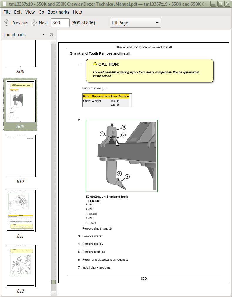
Shank and Tooth Remove and Install
Group 4260: Hydraulic System
Ripper Cylinder Remove and Install
Section 99: Dealer Fabricated Tools
Group 9900: Dealer Fabricated Tools
DF1041 Track Nut Removal Tool
DF1063 Final Drive Lift Bracket
DFT1087 Track Recoil Spring Disassembly and Assembly Guard Tool
DFT1119 Pump Support
DFT1130 Adapter
DFT1132 Hydrostatic Motor Removal and Installation Tool
DFT1137 Hydrostatic Motor Removal and Installation Tool
DFT1166 Final Drive Lifting Bracket Adapter
DFT1167 Final Drive Lifting Bracket Adapter Spacer
DFT1211 Final Drive Lifting Bracket Adapter
DFT1278 30 mm Wrench with 3/4 in. Drive
ST4920 Track Recoil Spring Disassembly and Assembly Tool
John Deere Crawler Dozers 550K, 650K Repair Service Manual (TM13357X19)
![]()