
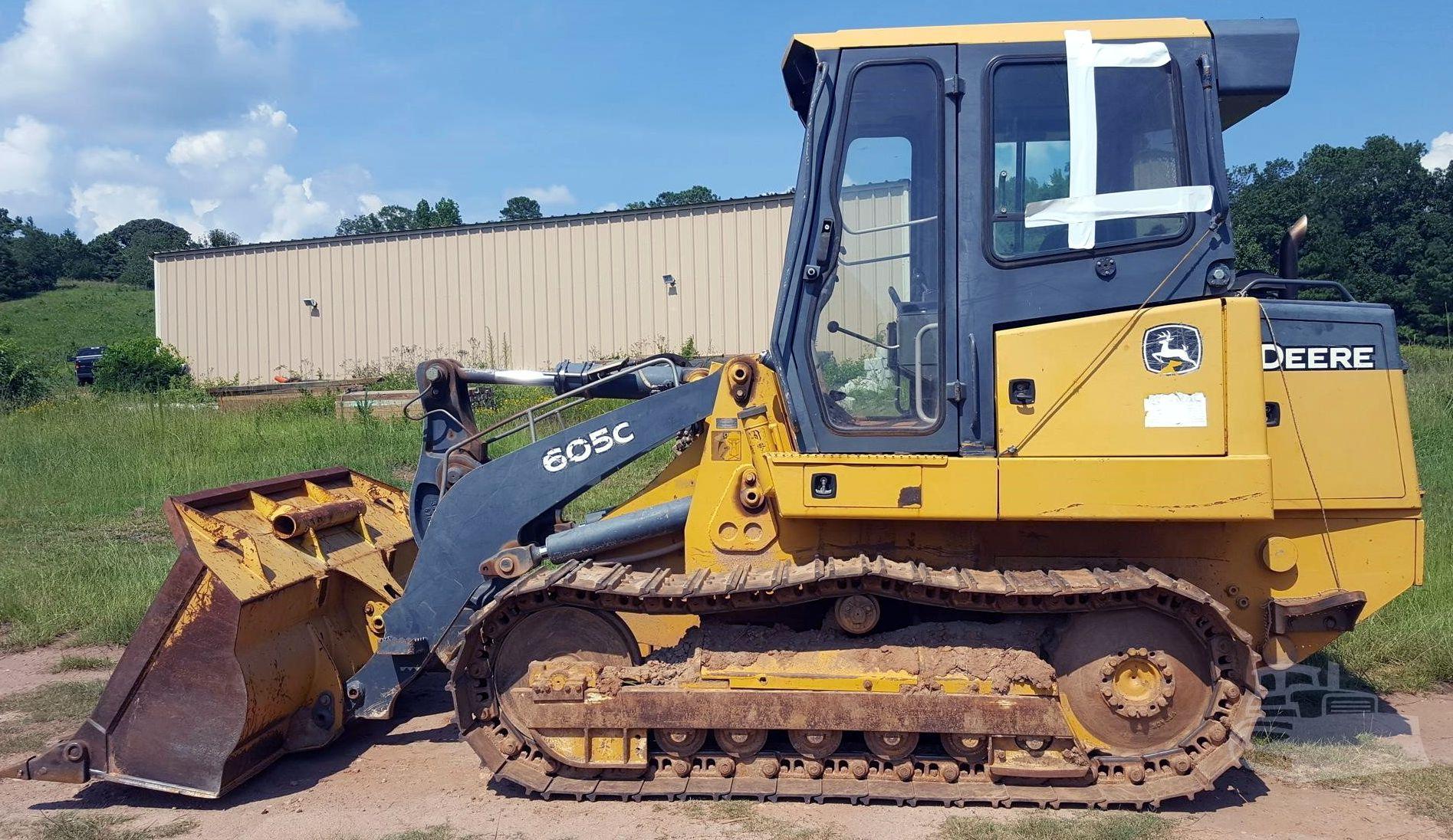
John Deere 605C Crawler Loader Operation and Test Service Manual (TM2353)
Complete Diagnosis and Test manual with Electrical Wiring Diagrams for John Deere 605C Crawler Loader, with all the service information to maintain, diagnose, and rebuild like professional mechanics.
John Deere 605C Crawler Loader Operation and Test manual includes:
* Numbered table of contents easy to use so that you can find the information you need fast.
* Detailed sub-steps expand on repair procedure information
* Numbered instructions guide you through every repair procedure step by step.
* Troubleshooting and electrical service procedures are combined with detailed wiring diagrams for ease of use.
* Notes, cautions and warnings throughout each chapter pinpoint critical information.
* Bold figure number help you quickly match illustrations with instructions.
* Detailed illustrations, drawings and photos guide you through every procedure.
* Enlarged inset helps you identify and examine parts in detail.
TM2353 - John Deere 605C Crawler Loader Technical Manual - Operation and Test.PDF
TM2353 - John Deere 605C Crawler Loader Technical Manual - Operation and Test.epub
Total Pages: 742 pages
File Format: PDF (bookmarked, ToC, Searchable, Printable, high quality)
Language: English
MAIN SECTIONS
Foreword
Technical Information Feedback Form
General Information
Safety
Diagnostic Trouble Codes (DTCs)
Engine Control Unit (ECU)
Transmission Control Unit (TCU)
Operational Checkout Procedure
System Operational Checks
Engine
Theory Of Operation
Diagnostic Information and Observed Symptoms
Tests
Electrical System
System Information
System Diagrams
Sub-System Diagnostics
References
Power Train
Theory of Operation
Diagnostic Information and Observed Symptoms
Pneumatic System
Theory of Operation
Diagnostic Information
Hydraulic System
Theory of Operation
Diagnostic Information and Observed Symptoms
Adjustments
Tests
Hydrostatic System
Theory of Operation
Diagnostic Information and Observed Symptoms
Adjustments
Test
Heating and Air Conditioning
Theory of Operation
Diagnostic Information and Observed Symptoms
Tests
Table of Contents - Expanded View
Foreword
Technical Information Feedback Form
Section 9000: General Information
Group 01: Safety
Recognize Safety Information
Follow Safety Instructions
Operate Only If Qualified
Wear Protective Equipment
Avoid Unauthorized Machine Modifications
Inspect Machine
Add Cab Guarding For Special Uses
Stay Clear of Moving Parts
Avoid High-Pressure Oils
Beware of Exhaust Fumes
Prevent Fires
Prevent Battery Explosions
Handle Chemical Products Safely
Dispose of Waste Properly
Prepare for Emergencies
Start Only From Operator's Seat
Use and Maintain Seat Belt
Prevent Unintended Machine Movement
Avoid Work Site Hazards
Keep Riders Off Machine
Avoid Backover Accidents
Avoid Machine Tip Over
Park And Prepare For Service Safely
Service Cooling System Safely
Remove Paint Before Welding or Heating
Make Welding Repairs Safely
Drive Metal Pins Safely
Section 9001: Diagnostic Trouble Codes (DTCs)
Group 01: Engine Control Unit (ECU)
Engine Control Unit (ECU) Diagnostic Trouble Codes (DTC)
Group 02: Transmission Control Unit (TCU)
TCU Diagnostic Trouble Codes Overview
!CAL - Calibrate TCU
F300 - The Transmission Control Lever (TCL) (B12) steer command sensor 2 voltage is less than 0.27 V
F301 - The Transmission Control Lever (TCL) (B12) steer command sensor 2 voltage is less than minimum calibration value
F304 - The Transmission Control Lever (TCL) (B12) steer command sensor 2 voltage is more than maximum calibration value
F305 - The Transmission Control Lever (TCL) (B12) steer command sensor 2 voltage is more than 4.81 V
F306 - The Transmission Control Lever (TCL) (B12) steer command sensor 2 right minimum calibration value is less than 0.85 V
F307 - The Transmission Control Lever (TCL) (B12) steer command sensor 2 right minimum calibration value is more than 1.15 V
F308 - The Transmission Control Lever (TCL) (B12) steer command sensor 2 left maximum calibration value is less than 3.85 V
F309 - The Transmission Control Lever (TCL) (B12) steer command sensor 2 left maximum calibration value is more than 4.15 V
F311 - At least one of the sensor voltages is less than 4.81 V
F314 - At least one of the sensor voltages is more than 5.5 V
F321 - The charging circuit battery voltage is less than 9.0 V
F324 - The charging circuit battery voltage is more than 16.5 V
F330 - The Transmission Control Lever (TCL) (B12) drive command sensor 1 voltage is less than 0.27 V
F331 - The Transmission Control Lever (TCL) (B12) drive command sensor 1 voltage is less than minimum calibration value
F334 - The Transmission Control Lever (TCL) (B12) drive command sensor 1 voltage is more than maximum calibration value
F335 - The Transmission Control Lever (TCL) (B12) voltage is more than 4.81 V
F336 - The Transmission Control Lever (TCL) (B12) drive command sensor 1 maximum reverse position calibration voltage is too low
F337 - The Transmission Control Lever (TCL) (B12) drive command sensor 1 maximum reverse position calibration voltage is too high
F338 - The Transmission Control Lever (TCL) (B12) drive command sensor 1 minimum forward position calibration voltage is too low
F339 - The Transmission Control Lever (TCL) (B12) drive command sensor 1 maximum forward position calibration voltage is too high
F33R - Transmission Control Lever (TCL) (B12) drive command 1 and drive command 2 voltage mismatch
F340 - The Transmission Control Lever (TCL) (B12) steer command sensor 1 voltage is less than 0.27 V
F341 - The Transmission Control Lever (TCL) (B12) steer command sensor 1 voltage is less than minimum calibration value
F344 - The Transmission Control Lever (TCL) (B12) steer command sensor 1 voltage is more than minimum calibration value
F345 - The Transmission Control Lever (TCL) (B12) steer command sensor 1 voltage is more than 4.81 V
F346 - The Transmission Control Lever (TCL) (B12) steer command sensor 1 left minimum calibration value is less than 0.85 V
F347 - The Transmission Control Lever (TCL) (B12) steer command sensor 1 left minimum calibration value is more than 1.15 V
F348 - The Transmission Control Lever (TCL) (B12) steer command sensor 1 right maximum calibration value is less than 3.85 V
F349 - The Transmission Control Lever (TCL) (B12) steer command sensor 1 right maximum calibration value is more than 4.15 V
F34R - Right steer and left steer voltage mismatch
F350 - The Decel/Brake Pedal Sensor (B60) voltage is below 0.27 V
F351 - The Decel/Brake Pedal Sensor (B60) decel pedal up value is out of range
F354 - The Decel/Brake Pedal Sensor (B60) decel pedal down value is out of range
F355 - The Decel/Brake Pedal Sensor (B60) voltage is more than 4.81 V
F356 - The Decel/Brake Pedal Sensor (B60) decel pedal lowered position minimum calibration value is too low
F357 - The Decel/Brake Pedal Sensor (B60) decel pedal lowered position minimum calibration value is too high
F358 - The Decel/Brake Pedal Sensor (B60) decel pedal up position maximum calibration value is to low
F359 - The Decel/Brake Pedal Sensor (B60) decel pedal down maximum calibration value is more than 3.75 V
F360 - The Transmission Control Lever (TCL) (B12) drive command sensor 2 voltage is less than 0.27 V
F361 - The Transmission Control Lever (TCL) (B12) drive command 2 voltage is less than minimum calibration value
F364 - The Transmission Control Lever (TCL) (B12) drive command 2 voltage is more than maximum calibration value
F365 - The Transmission Control Lever (TCL) (B12) drive command 2 voltage is more than 4.81 V
F366 - The Transmission Control Lever (TCL) (B12) drive command sensor 2 minimum calibration value is less than 0.85 V
F367 - The Transmission Control Lever (TCL) (B12) minimum calibration value is more than 1.15 V
F368 - The Transmission Control Lever (TCL) (B12) maximum calibration value is less than 3.85 V
F369 - The Transmission Control Lever (TCL) (B12) maximum calibration value is more than 4.15 V
F370 - The motor speed sensor left (B63) signal voltage is below 0.11 V
F372 - The motor speed sensor left (B63) signal voltage is between 1.10—3.81 V
F373 - The motor speed sensor left (B63) is drawing more than 20 mA and the speed is 0 rpm
F375 - The motor speed sensor left (B63) signal voltage is greater than 4.81 V
F380 - The motor speed sensor right (B64) signal voltage is below 0.11 V
F382 - The motor speed sensor right (B64) signal voltage is between 1.10— 3.81 V
F383 - The motor speed sensor right (B64) is drawing more than 20 mA and the speed is 0 rpm
F385 - The motor speed sensor right (B64) signal voltage is greater than 4.81 V
F393 - ECU communication loss
F395 - The engine speed signal is greater than 8129 rpm
F3A0 - The pump Pressure Control Pilot (PCP) solenoid (Left) (Y77) is limited to reverse direction and current draw is too high in forward direction
F3A5 - The pump Pressure Control Pilot (PCP) solenoid (Left) (Y77) is limited to reverse direction and current draw is too low in forward direction
F3A6 - The pump Pressure Control Pilot (PCP) solenoid (Left) (Y77) is limited to the reverse direction and the forward threshold (point of track movement) is too low
F3A7 - The pump Pressure Control Pilot (PCP) solenoid (Left) (Y77) is limited to the reverse direction and the forward threshold (point of track movement) is too high
F3A8 - The pump Pressure Control Pilot (PCP) solenoid (Left) (Y77) maximum calibration speed value is too low in forward
F3A9 - The pump Pressure Control Pilot (PCP) solenoid (Left) (Y77) maximum calibration speed value is too high in forward
F3B8 - The Decel/Brake Pedal Sensor (B60) brake calibration value is too low
F3B9 - The Decel/Brake Pedal Sensor (B60) brake calibration value is too high
F3B3 - A problem with the decelerator sensor (B60) exists
F3C0 - The pump Pressure Control Pilot (PCP) solenoid (Right) (Y78) is limited to reverse direction and current draw is too high in forward direction
F3C5 - The pump Pressure Control Pilot (PCP) solenoid (Right) (Y78) is limited to reverse direction and current draw is too low in forward direction
F3C6 - The pump Pressure Control Pilot (PCP) solenoid (Right) (Y78) is limited to the reverse direction and the forward threshold (point of track movement) is too low
F3C7 - The pump Pressure Control Pilot (PCP) solenoid (Right) (Y78) is limited to the reverse direction and the forward threshold (point of track movement) is too high
F3C8 - The pump Pressure Control Pilot (PCP) solenoid (Right) (Y78) maximum calibration speed value is too low in forward
F3C9 - The pump Pressure Control Pilot (PCP) solenoid (Right) (Y78) maximum calibration speed value is too high in forward
F3D0 - The pump Pressure Control Pilot (PCP) solenoid (Right) (Y78) is limited to forward direction and current draw is too high in reverse direction
F3D5 - The pump Pressure Control Pilot (PCP) solenoid (Right) (Y78) is limited to forward direction and current draw is too low in reverse direction
F3D6 - The pump Pressure Control Pilot (PCP) solenoid (Right) (Y78) is limited to the forward direction and the reverse threshold (point of track movement) is too low
F3D7 - The pump Pressure Control Pilot (PCP) solenoid (Right) (Y78) is limited to the forward direction and the reverse threshold (point of track movement) is too high
F3D8 - The pump Pressure Control Pilot (PCP) solenoid (Right) (Y78) maximum calibration speed value is too low in reverse
F3D9 - The pump Pressure Control Pilot (PCP) solenoid (Right) (Y78) maximum calibration speed value is too high in reverse
F3E0 - The pump Pressure Control Pilot (PCP) solenoid (Left) (Y77) is limited to forward direction and current draw is too high in reverse direction
F3E5 - The pump Pressure Control Pilot (PCP) solenoid (Left) (Y77) is limited to forward direction and current draw is too low in reverse direction
F3E6 - The pump Pressure Control Pilot (PCP) solenoid (Left) (Y77) is limited to the forward direction and the reverse threshold (point of track movement) is too low
F3E7 - The pump Pressure Control Pilot (PCP) solenoid (Left) (Y77) is limited to the forward direction and the reverse threshold (point of track movement) is too high
F3E8 - The pump Pressure Control Pilot (PCP) solenoid (Left) (Y77) maximum calibration speed value is too low in reverse
F3E9 - The pump Pressure Control Pilot (PCP) solenoid (Left) (Y77) maximum calibration speed value is too high in reverse
F3J0 - Incorrect Transmission Control Lever (TCL) configuration
F3J5 - Incorrect Transmission Control Lever (TCL) configuration
F3K3 - A problem with the motor shift solenoid right (Y76) exists
F3L3 - A problem with the motor shift solenoid left (Y75) exists
F3M0 - The steering pedal sensor—left (B61) output voltage is less than 0.27 V
F3M1 - The steering pedal sensor—left (B61) output voltage is less than minimum calibration value
F3M4 - The steering pedal sensor—left (B61) output voltage is more than maximum calibration value
F3M5 - The steering pedal sensor—left (B61) output voltage is more than 4.81 V
F3M6 - The steering pedal sensor—left (B61) minimum calibration value is less than 2.40 V
F3M7 - The steering pedal sensor—left (B61) minimum calibration value is more than 3.00 V
F3M8 - The steering pedal sensor—left (B61) maximum calibration value is less than 3.40 V
F3M9 - The steering pedal sensor—left (B61) maximum calibration value is more than 4.00 V
F3N0 - The steering pedal sensor—right (B62) output voltage is less than 0.27 V
F3N1 - The steering pedal sensor—right (B62) output voltage is less than minimum calibration value
F3N4 - The steering pedal sensor—right (B62) output voltage is more than maximum calibration value
F3N5 - The steering pedal sensor—right (B62) output voltage is more than 4.81 V
F3N6 - The steering pedal sensor—right (B62) minimum calibration value is less than 2.40 V
F3N7 - The steering pedal sensor—right (B62) minimum calibration value is more than 3.00 V
F3N8 - The steering pedal sensor—right (B62) maximum calibration value is less than 3.40 V
F3N9 - The steering pedal sensor—right (B62) maximum calibration value is more than 4.00 V
F3P0 - A short circuit in the park lock lever switch circuit exists
F3P5 - An open circuit in the park lock lever switch circuit exists
F3U0 - The engine speed control switch (S21) voltage is less than 0.27 V
F3U1 - The engine speed control switch (S21) value is out of range (low)
F3U4 - The engine speed control switch (S21) value is out of range (high)
F3U5 - The engine speed control switch (S21) voltage is more than 4.81 V
F3U6 - The engine speed control switch (S21) slow idle position calibration voltage is less than 0.45 V
F3U7 - The engine speed control switch (S21) slow idle position calibration voltage is more than 1.22 V
F3U8 - The engine speed control switch (S21) fast idle position calibration voltage is less than 2.96 V
F3U9 - The engine speed control switch (S21) fast idle position calibration voltage is more than 3.97 V
Section 9005: Operational Checkout Procedure
Group 10: System Operational Checks
Operational Checkout
Section 9010: Engine
Group 05: Theory Of Operation
POWERTECH POWERTECH is a trademark of Deere & Company 4.5 L (4045) John Deere Engine
Cold Weather Starting Aid Operation
Group 15: Diagnostic Information and Observed Symptoms
Engine Diagnose Malfunctions
Group 25: Tests
Slow and Fast Idle Test
Fuel System Test
Turbocharger Boost Pressure Test
Section 9015: Electrical System
Group 05: System Information
Electrical Diagram Information
Group 10: System Diagrams
Fuse and Relay Specifications
System Functional Schematic, Wiring Diagram, and Component Location Legend
System Functional Schematic and Schematic Legend
Main Wire Harness (W10) and Engine Harness Component Location
Main Wire Harness (W10) and Engine Harness Wiring Diagram
Instrument Panel Wire Harness (W11) Component Location
Instrument Panel Wire Harness (W11) Wiring Diagram
Overhead Console Wire Harness (W12) Component Location
Overhead Console Wire Harness (W12) Wiring Diagram
Air Conditioning Wire Harness (W14 and W15) Component Location
Air Conditioning Wire Harness (W14 and W15) Wire Diagram
Group 15: Sub-System Diagnostics
Controller Area Network (CAN) Theory of Operation
Engine Control Unit (ECU) Theory of Operation
Starting and Charging Circuit Theory of Operation
Transmission Control Unit (TCU) Circuit Theory of Operation
Fan Control Unit (FCU) Circuit Operation
Group 20: References
Access Transmission Control Unit (TCU) Diagnostic Trouble Codes (DTCs)
Access Diagnostic Display Unit (DDU) Information
Battery Electrolyte Level And Terminals Check
Battery Test Procedure
Alternator Test Procedure
Transmission Control Unit (TCU) Calibration
Decel/Brake and Steering Pedal Test
Decel/Brake Pedal Adjustment
Electrical Component Specifications
DEUTSCH DEUTSCH is a trademark of the Deutsch Co. Connector Service
Amp Connector Service
Cannon Connector Service
Rotary Sensor Remove and Install
Section 9020: Power Train
Group 05: Theory of Operation
Dampener Drive Operation
Splitter Drive Operation
Group 15: Diagnostic Information and Observed Symptoms
Splitter Drive Overheating
Splitter Drive Noisy
Section 9022: Pneumatic System
Group 05: Theory of Operation
Air Suspension Seat Operation
Group 15: Diagnostic Information
Air Suspension Seat Schematic
Section 9025: Hydraulic System
Group 05: Theory of Operation
Hydraulic System Operation
Main Hydraulic Pump Operation
Hydraulic Reservoir Operation
Main Hydraulic Filter Operation
Fan Drive Pump and Motor Circuit Operation
Control Valve Operation
Solenoid Valve Manifold Operation
Load Sense System Relief Valve Operation
Inlet Valve Section Operation
Pilot Control Valve Operation
Pilot Control Valve Connections
Bucket Control Valve Section Operation—Neutral
Boom Control Valve Section Operation
Auxiliary Control Valve Section Operation—Multipurpose Bucket
Group 15: Diagnostic Information and Observed Symptoms
Hydraulic System Schematic
Hydraulic Component Location
Main Hydraulic Component Connections
Main Control Valve Component Location
Multipurpose Bucket Hydraulic System Schematic
No Hydraulics
Slow Hydraulic Functions
Slow Hydraulics—One Function Only
No Hydraulic Power in One Function
Low Hydraulic Power (Low Hydraulic Pressure)
Boom Float Does Not Function
Hydraulic Function Makes Chattering Noise
Functions Drift
Control Valve Sticks
Hydraulic Oil Overheats
Foaming Oil
Hydraulic Pump Leaking
Excessive Pump Noise
Group 20: Adjustments
Return-to-Dig Adjustment
Boom Height Kick Adjustment
Case Drain Filter Inspection
Group 25: Tests
Diagnostic Display Unit (DDU) Information For Checking Engine Speed
JT02156A Digital Pressure/Temperature Analyzer Installation
JT05800 Digital Thermometer Installation
Hydraulic Oil Warm-Up Procedure
Hydraulic System Pressure Release
Hydraulic Accumulator Pressure Discharge
Hydraulic Accumulator Precharge Pressure Test
Main Hydraulic Pump Flow Test
Load Sense System Relief Valve Pressure Test
Control Valve Load Sense (LS) Differential Pressure Test
Pilot Oil Pressure Test
Pilot Control Valve Pressure Test
Circuit Relief Valve Test—With Remote Pump
Cooling Fan Speed Test
Cooling Fan Pump Pressure Test
Cooling Fan Pump Flow Test
Boom and Bucket Cylinder Drift Test
Clam Cylinder Drift Test
Cylinder Leakage Test
Section 9026: Hydrostatic System
Group 05: Theory of Operation
Hydrostatic System
Transmission Control Circuit—Flow Chart
Charge Pump Operation
Hydrostatic Filter Operation
Neutral Charge Relief Valve Operation
Park Brake Operation
Multi-Function Valve Operation
Pump Pressure Control Pilot (PCP) Operation
Pump Displacement Control Valve (PDCV) Operation
Hydrostatic Pump Operation
Flushing Valve and Operating Charge Relief Valve Operation
Hydrostatic Motor Operation
Group 15: Diagnostic Information and Observed Symptoms
Hydrostatic Schematic—Neutral (Park Brake ON)
Hydrostatic System Component Location
Hydrostatic System Diagram—Park Brake On (Neutral)
Hydrostatic System Diagram—Forward (Slow Speed)
Hydrostatic System Diagram—Reverse (Fast Speed)
Overheating
High/Low Charge Pressure
Mistrack/Indexes
Machine Will Not Reach Full Speed
Low Power
Engine Starts But Both Tracks Either Do Not Move Or Come To A Stop
Moves Only One Direction Or One Track Won't Move
Group 20: Adjustments
Dual Axis Transmission Control Lever (TCL) Adjustment
Group 25: Test
Hydrostatic Pump and Motor Initial Start-Up Procedure
Hydrostatic Pump Flushing Procedure
Pressure Control Pilot (PCP) Manual Override Test
Pressure Control Pilot (PCP) Test
Pressure Control Pilot (PCP) Internal Adjustment
Multi-Function Relief Valve Test
Transmission Efficiency Test
Neutral Charge Relief and Operating Charge Relief Pressure Test
Pump Displacement Control Valve (PDCV) Neutral (Null) Adjustment
Pump Servo Pressure Test
Hydrostatic Motor Min./Max. Angle Servo Piston Pressure Test
Hydrostatic Motor Min. Angle Stop Adjustment
Charge Pump Flow Test
Towing the Machine
Section 9031: Heating and Air Conditioning
Group 05: Theory of Operation
Air Conditioning System Cycle of Operation
Group 15: Diagnostic Information and Observed Symptoms
Air Conditioning Component Location
Air Conditioning System Does Not Operate
Air Conditioning System Does Not Cool
Air Conditioner Runs Constantly or Only For a Short Time
System Cools Insufficiently
Noise on Air Conditioning Compressor Clutch
Heater System Does Not Operate
Heater Does Not Warm Interior of Cab
Interior Windows Continue To Fog
Group 25: Tests
Proper Refrigerant Handling
R134a Refrigerant Cautions
R134a Oil Charge Capacity
R134a Refrigerant Charge Capacity
Refrigerant Hoses And Tubing Inspection
R134a Air Conditioning System Test
Operating Pressure Diagnostic Chart
Expansion Valve Operating Test
Blower Motor Switch Test
Blower Motor Resistor Test
Heater Blower Motor Test
Air Conditioner Low Pressure Switch Test
Air Conditioner High Pressure Switch Test
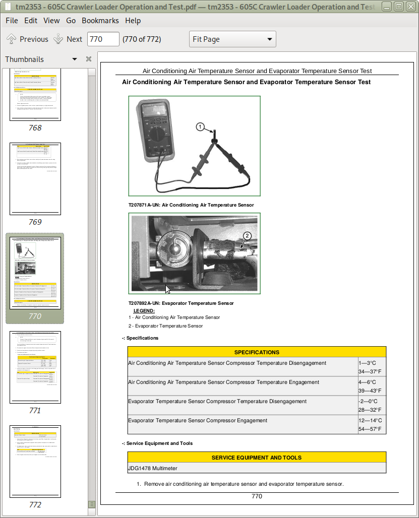
Air Conditioning Air Temperature Sensor and Evaporator Temperature Sensor Test
Leak Testing
![]()