
John Deere 605C Crawler Loader Repair Service Manual (TM2354)
Complete service repair manual for John Deere 605C Crawler Loader, with all the shop information to maintain, repair, and rebuild like professional mechanics.
John Deere 605C Crawler Loader workshop service repair manual includes:
* Numbered table of contents easy to use so that you can find the information you need fast.
* Detailed sub-steps expand on repair procedure information
* Numbered instructions guide you through every repair procedure step by step.
* Notes, cautions and warnings throughout each chapter pinpoint critical information.
* Bold figure number help you quickly match illustrations with instructions.
* Detailed illustrations, drawings and photos guide you through every procedure.
* Enlarged inset helps you identify and examine parts in detail.
TM2354 - John Deere 605C Crawler Loader Technical Manual - Repair.PDF
TM2354 - John Deere 605C Crawler Loader Technical Manual - Repair.epub
Total Pages: 612 pages
File Format: PDF/EPUB/MOBI/AZW (PC/Mac/Android/Kindle/iPhone/iPad; bookmarked, ToC, Searchable, Printable)
Language: English
MAIN SECTIONS
Foreword
HELP!! HELP!! HELP!! HELP!!
General Information
Safety
Torque Values
Tracks
Track System
Axles and Suspension Systems
Drive Axle Housing and Support
Axle Shaft, Bearings, and Reduction Gear
Transmission
Removal and Installation
Controls Linkage
Hydrostatic System
Engine
Removal and Installation
Engine Auxiliary Systems
Cold Weather Starting Aids
Radiator and Fan Shroud
External Fuel Supply System
Dampener Drive
Elements
Transfer or Splitter Drive
Removal and Installation
Gears, Shafts, and Bearings
Park Brake
Removal and Installation
Control Linkage
Hydraulic System
Frame or Supporting Structure
Frame Installation
Frame Bottom Guards
Chassis Weights
Operator`s Station
Removal and Installation
Operator`s Enclosure
Seat and Seat Belt
Heating and Air Conditioning
Sheet Metal and Styling
Hood and Engine Enclosure
Grille and Grille Housing
Main Hydraulic System
Hydraulic System
Loader
Bucket
Frames
Hydraulics
Ground Conditioning Tool
Remove and Install
Blades, Teeth, and Shanks
Hydraulic System
Dealer Fabricated Tools
Table of Contents - Expanded View
Foreword
HELP!! HELP!! HELP!! HELP!!
Section 00: General Information
Group 01: Safety
Recognize Safety Information
Follow Safety Instructions
Operate Only If Qualified
Wear Protective Equipment
Avoid Unauthorized Machine Modifications
Inspect Machine
Stay Clear of Moving Parts
Avoid High-Pressure Fluids
Beware of Exhaust Fumes
Prevent Fires
Prevent Battery Explosions
Handle Chemical Products Safely
Dispose of Waste Properly
Prepare for Emergencies
Use Steps and Handholds Correctly
Add Cab Guarding For Special Uses
Start Only From Operator's Seat
Use and Maintain Seat Belt
Prevent Unintended Machine Movement
Avoid Work Site Hazards
Use Special Care When Operating Loader
Add and Operate Attachments Safely
Keep Riders Off Machine
Avoid Backover Accidents
Avoid Machine Tip Over
Park And Prepare For Service Safely
Service Cooling System Safely
Remove Paint Before Welding or Heating
Make Welding Repairs Safely
Drive Metal Pins Safely
Live With Safety
Group 03: Torque Values
Metric Standard Thread Bolts and Cap Screws Torque Values
Metric Fine Thread Bolts and Cap Screws Torque Values
O-Ring Face Seal Fittings With Metric Hex Nut And Stud End For Standard Pressure Service Recommendations
O-Ring Face Seal Fittings With Metric Hex Nut And Stud End For High Pressure Service Recommendations
Metric Series Four-Bolt Flange Fittings For Standard Pressure, SAE Code 61, Service Recommendations
Metric Series Four Bolt Flange Fitting For High Pressure, SAE Code 62, Service Recommendations
Oil Drain Plugs For Final Drive Service Recommendations
Metric 24° O-Ring Seal DIN 20078 Service Recommendations
Section 01: Tracks
Group 0130: Track System
Rock Guards and Chain Guides Remove and Install
Carrier Roller Remove and Install
Carrier Roller Disassemble and Assemble
Metal Face Seals Inspection
Track Roller Remove and Install
Track Roller Disassemble and Assemble
Track Roller Leakage Test
Track Shoe Remove and Install
Sealed Track Chain Removal
Sealed Track Chain Disassemble and Assemble
Sealed Track Chain Installation
Front Idler Remove and Install
Front Idler Disassemble, Inspect, and Assemble
Front Idler Adjustment
Front Idler Oil Level Check
Track Tension Adjuster Remove and Disassemble
Track Tension Adjuster Assemble and Install
Track Idler Recoil Spring Remove and Install
Track Idler Recoil Spring Disassemble and Assemble
Sprocket Remove and Install
Track Frame Remove and Install
Frame Wear Strips Remove and Install
Section 02: Axles and Suspension Systems
Group 0201: Drive Axle Housing and Support
Final Drive Remove and Install
Group 0250: Axle Shaft, Bearings, and Reduction Gear
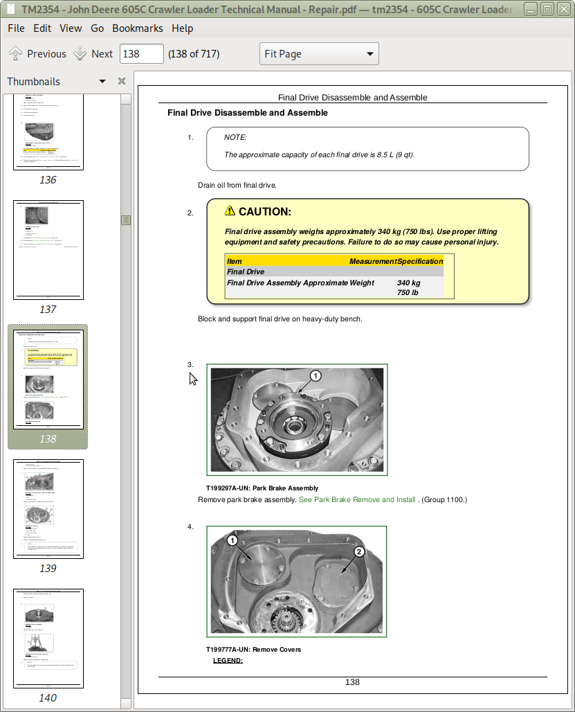
Final Drive Disassemble and Assemble
Section 03: Transmission
Group 0300: Removal and Installation
Hydrostatic Pump Remove and Install
Hydrostatic Motor Remove and Install
Group 0315: Controls Linkage
Transmission Control Lever (TCL) Adjustment
Decel/Brake and Steering Pedals Assembly Remove and Install
Steering Pedals Disassemble and Assemble
Decel/Brake Pedal Disassemble and Assemble
Group 0360: Hydrostatic System
Hydrostatic Pumps Disassemble
Hydrostatic Charge Pump Disassemble and Assemble
Pump Displacement Control Valve (PDCV) Disassemble and Assemble
Multi-Function Valve Disassemble and Assemble
Neutral Charge Relief Valve Disassemble and Assemble
Hydrostatic Pump Assemble
Hydrostatic Motor Disassemble
Hydrostatic Motor Assemble
Section 04: Engine
Group 0400: Removal and Installation
Engine Remove and Install
Section 05: Engine Auxiliary Systems
Group 0505: Cold Weather Starting Aids
Ether Start Aid Remove and Install
Starting Aid Solenoid Remove and Install
Group 0510: Radiator and Fan Shroud
Cooling Package Remove and Install
Radiator and Oil Cooler Remove and Install
Group 0560: External Fuel Supply System
Fuel Tank Remove and Install
Section 07: Dampener Drive
Group 0752: Elements
Dampener Drive Remove and Install
Section 08: Transfer or Splitter Drive
Group 0800: Removal and Installation
Splitter Drive Remove and Install
Group 0851: Gears, Shafts, and Bearings
Splitter Drive Disassemble and Assemble
Section 11: Park Brake
Group 1100: Removal and Installation
Park Brake Remove and Install
Group 1115: Control Linkage
Park Lock Lever Remove and Install
Park Lock Lever Disassemble and Assemble
Group 1160: Hydraulic System
Park Brake Solenoid Valve Remove and Install
Park Brake Disassemble and Assemble
Section 17: Frame or Supporting Structure
Group 1740: Frame Installation
Welding Repair of Major Structures
Group 1746: Frame Bottom Guards
Bottom Guards Remove and Install
Group 1749: Chassis Weights
Rear Counterweight Remove and Install
Section 18: Operator's Station
Group 1800: Removal and Installation
Cab/Canopy Platform Remove and Install
Cab/Canopy (ROPS) Remove and Install
Group 1810: Operator's Enclosure
Sliding Window Remove and Install
Windowpane and Two Piece Molding Remove and Install
Front Window Wiper Remove and Install
Rear Window Wiper Remove and Install
Window Washer Pumps Remove and Install
Group 1821: Seat and Seat Belt
Standard Suspension Seat Remove and Install
Standard Suspension Seat Disassemble and Assemble
Air Suspension Seat Remove and Install
Air Suspension Seat Disassemble and Assemble
Group 1830: Heating and Air Conditioning
Refrigerant Cautions and Proper Handling
R134a Compressor Oil Charge Check
R134a Compressor Oil Removal
R134a Component Oil Charge
Leakage Testing
R134a Refrigerant Recovery/Recycling and Charging Station Installation Procedure
Recover R134a Refrigerant
Evacuate R134a System
Charge R134a System
Air Conditioner System Cleaning Procedures
Flush and Purge Air Conditioner System
Evaporator or Heater Core Remove and Install
Expansion Valve Remove and Install
Air Conditioning Temperature Sensor and Evaporator Temperature Sensor Remove and Install
Cab Blower Motor and Blower Motor Resistor Remove and Install
Cab Heater/Air-Conditioning Unit Disassemble and Assemble
Receiver-Dryer Remove and Install
Condenser Remove and Install
Compressor Remove and Install
Compressor Clutch Disassemble and Assemble
Clutch Hub Clearance Check
Compressor Manifold Inspect
Compressor Disassemble and Assemble
Section 19: Sheet Metal and Styling
Group 1910: Hood and Engine Enclosure
Hood and Engine Compartment Doors Remove and Install
Group 1921: Grille and Grille Housing
Grille Remove and Install
Section 21: Main Hydraulic System
Group 2160: Hydraulic System
Case Drain Filter Inspection
Hydraulic Pump Remove and Install
Hydraulic Fan Pump Remove and Install
Hydraulic Fan Proportional Solenoid and Relief Valve Remove and Install
Hydraulic Fan Motor Remove and Install
Hydraulic Fan Motor Disassemble and Assemble
Hydraulic Reservoir Remove and Install
Hydraulic Charge Filter Remove and Install
Hydraulic Charge Filter Assembly Disassemble and Assemble
Section 31: Loader
Group 3102: Bucket
General and Multipurpose Bucket Remove and Install
Multipurpose Bucket and Lines Disassemble and Assemble
Cracked Cutting Edge Repair
Group 3140: Frames
Boom Remove and Install
Group 3160: Hydraulics
Loader Control Valve Remove and Install
Loader Control Valve Disassemble and Assemble
System Pressure Relief Valve (Load Sensing) Remove and Install
Pilot Control Valve (PCV) Remove and Install
Bucket Cylinder Remove and Install
Boom Cylinder Remove and Install
Boom And Bucket Cylinder Disassemble And Assemble
Multipurpose Bucket Cylinder Disassemble and Assemble
Section 42: Ground Conditioning Tool
Group 4200: Remove and Install
Ripper Remove and Install
Group 4201: Blades, Teeth, and Shanks
Shank and Tooth Remove and Install
Group 4260: Hydraulic System
Auxiliary Control Valve Disassemble and Assemble
Auxiliary Pilot Control Valve Remove and Install
Ripper Cylinder Remove and Install
Ripper Cylinder Disassemble and Assemble
Section 9900: Dealer Fabricated Tools
Group 0999: Dealer Fabricated Tools
DF1041 Track Nut Removal Tool
DF1063 Final Drive Lift Bracket
DF1065 Final Drive and Pump Adapter Bracket
DFRW20 Compressor Holding Fixture
DFT1087 Track Recoil Spring Disassembly and Assembly Guard Tool
DFT1119 Pump Support
DFT1167 Final Drive Lifting Bracket Adapter Spacer
DFT1211 Final Drive Lifting Bracket Adapter
DFT1243 Lifting Bracket Extension
DFT1250 Lifting Bracket
DFT1260 Final Drive Lifting Fixture
DFT1270 Final Drive Lifting Bracket Adapter
DFT1271 Retainer Plate
DFT1272 18 mm Wrench with 1/2 in. Drive
ST4920 Track Recoil Spring Disassembly and Assembly Tool
![]()