
John Deere 300C Articulated Dump Truck Repair & Service Manual - TM1788
Complete repair service manual for John Deere 300C Articulated Dump Truck, with all the workshop information to maintain, repair, and service like professional mechanics.
John Deere 300C Articulated Dump Truck workshop service repair manual includes:
* Numbered table of contents easy to use so that you can find the information you need fast.
* Detailed sub-steps expand on repair procedure information
* Numbered instructions guide you through every repair procedure step by step.
* Notes, cautions and warnings throughout each chapter pinpoint critical information.
* Bold figure number help you quickly match illustrations with instructions.
* Detailed illustrations, drawings and photos guide you through every procedure.
* Enlarged inset helps you identify and examine parts in detail.
TM1788 - John Deere 300C Articulated Dump Truck Technical Manual (Repair).PDF
Total Pages: 1,177 pages
File Format: PDF (bookmarked, Searchable, Printable, high quality)
Language: English
MAIN SECTIONS
Foreword
General Information
Safety
General Specifications
Torque Values
Fuels and Lubricants
Wheels
Powered Wheels and Fastenings
Axles and Suspension Systems
Removal and Installation
Differential or Bevel Drive
Input Drive Shafts and U-Joints
Axle Mounting Parts
Axle Shaft, Bearings, and Reduction Gears
Transmission
Removal and Installation
Input Drive Shafts and U-Joints
Gears, Shafts, Bearings and Power Shift Clutch
Hydraulic System
Engine
Removal and Installation
Crankshaft, Main Bearings, and Flywheel
Camshaft and Timing Gear Train
Cylinder Block, Liners, Pistons and Rods
Lubrication System
Cylinder Head and Valves
Exhaust System
Fuel Injection System
Air Intake Manifold System
Cooling System
Thermostats, Housing and Water Piping
Engine Auxiliary System
Cold Weather Starting Aids
Cooling Systems
Speed Controls and Fuel Shut-Off Linkage
Intake System
External Exhaust Systems
Engine Mounting
External Fuel Supply Systems
Dampener Drive
Elements
Steering System
Secondary Steering
Hydraulic System
Service Brakes
Active Elements
Service Brake Hydraulic System
Park Brake
Active Elements
Electrical System
Batteries, Support, and Cables
Alternator, Regulator and Charging System Wiring
Lighting System
Wiring Harness and Switches
System Controls
Instruments and Indicators
Motors and Actuators
Frame and Supporting Structure
Frame Installation
Frame Bottom Guards
Operator`s Station
Removal and Installation
Operator Enclosure
Seat and Seat Belt
Steps and Handholds
Heating and Air Conditioning
Sheet Metal and Styling
Hood or Engine Enclosure
Safety and Convenience
Mirror
Horn and Warning Devices
Main Hydraulic System
Hydraulic System
Pneumatic Systems
Pumps and Drives Air Compressor
Pneumatic Control Valves
Reservoir, Filter, and Trap
Pneumatic Cylinders
Haulage Device
Frames
Hydraulic System
Dealer Fabricated Tools
tm1788 - 300C Articulated Dump Truck
Table of Contents
Foreword
Technical Information Feedback Form
Section 00: General Information
Group 0001: Safety
Handle Fluids Safely—Avoid Fires
Prevent Battery Explosions
Prepare for Emergencies
Prevent Acid Burns
Handle Chemical Products Safely
Avoid High-Pressure Fluids
Park Machine Safely
Support Machine Properly
Wear Protective Clothing
Work in Clean Area
Service Machines Safely
Work in Ventilated Area
Illuminate Work Area Safely
Replace Safety Signs
Use Proper Lifting Equipment
Remove Paint Before Welding or Heating
Avoid Heating Near Pressurized Fluid Lines
Service Tires Safely
Practice Safe Maintenance
Use Proper Tools
Dispose of Waste Properly
Live with Safety
Group 0002: General Specifications
Articulated Dump Truck
Articulated Dump Truck Specifications
Drain and Refill Capacities
Group 0003: Torque Values
Hardware Torque Specifications
Metric Bolt and Screw Torque Values
Additional Metric Cap Screw Torque Values
Unified Inch Bolt and Screw Torque Values
Metric Cap Screw and Nut Torque Values
Imperial and SAE (Inch) Cap Screw and Nut Torque Valves
Check Oil Lines and Fittings
Service Recommendations for O-Ring Boss Fittings
Service Recommendations for Flat Face O-Ring Seal Fittings
Service Recommendations for Metric Series Four Bolt Flange Fitting
Service Recommendations for Inch Series Four Bolt Flange Fittings
Group 0004: Fuels and Lubricants
Diesel Fuel
Lubricity of Diesel Fuels
Low Sulfur Diesel Fuel Conditioner
Diesel Fuel Storage
Fuel Tank
Do Not Use Galvanized Containers
Diesel Engine Oil — Non-Emissions Certified and Certified Tier 1 and Stage I
Transmission and Hydraulic Oil
Multipurpose Lubricant (Axles and Final Drives)
Grease
Oil Filters
Lubricant Storage
Alternative and Synthetic Lubricants
Mixing of Lubricants
Section 01: Wheels
Group 0110: Powered Wheels and Fastenings
Service Equipment and Tools
Specifications
Remove and Install Wheel
Remove and Install Tire
Check Tire Pressure
Section 02: Axles and Suspension Systems
Group 0200: Removal and Installation
Service Equipment and Tools
Specifications
Remove and Install Front Axle
Remove and Install Middle Axle
Remove and Install Rear Axle
Group 0210: Differential or Bevel Drive
Essential Tools
Service Equipment and Tools
Other Material
Specifications
Remove and Install Front or Rear Axle Differential
Disassemble and Assemble Front or Rear Axle Differentials
Remove and Install Middle Axle Differential
Disassemble and Assemble Middle Axle Differential
Remove and Install Middle Axle Differential Through Drive Shaft
Group 0225: Input Drive Shafts and U-Joints
Service Equipment and Tools
Specifications
Remove and Install Drive Shaft and U-Joint
Remove and Install Oscillation Joint Drive Shaft
Disassemble and Assemble Oscillation Joint Drive Shaft
Group 0242: Axle Mounting Parts
Service Equipment and Tools
Remove and Install Drag Link
Remove and Install Rear Axle Stabilizer Bar
Remove and Install Middle Axle Stabilizer Bar
Remove and Install Walking Beam
Remove and Install Rear Axle Walking Beam Absorber
Remove and Install Middle Axle Walking Beam Absorber
Remove and Install Shock Absorber
Remove and Install Front Axle Restraining Cable
Remove and Install Trailing Arm Bushing
Group 0250: Axle Shaft, Bearings, and Reduction Gears
Service Equipment and Tools
Other Material
Specifications
Remove and Install Final Drive Planetary
Disassemble and Assemble Final Drive Planetary
Remove and Install Axle Shaft
Disassemble and Assemble Wheel Hub
Section 03: Transmission
Group 0300: Removal and Installation
Essential Tools
Service Equipment and Tools
Specifications
Remove and Install Transmission
Group 0325: Input Drive Shafts and U-Joints
Specifications
Remove and Install Transmission-to-Engine Drive Shaft
Group 0350: Gears, Shafts, Bearings and Power Shift Clutch
Essential Tools
Service Equipment and Tools
Other Material
Specifications
Remove and Install Torque Converter (Transmission in Truck)
Remove Torque Converter and Housing
Install Torque Converter and Housing
Remove Clutches, Input, and Output Shafts
Install Clutches, Input, and Output Shafts
Disassemble and Assemble Inter-Axle Lock Actuator
Disassemble Clutch Pack KV (Forward) and KR (Reverse)
Assemble Clutch Pack KV (Forward) and KR (Reverse)
Disassemble Clutch Pack K1 (C1), K2 (C2), and K3 (C3)
Install K1 (C1), K2 (C2), and K3 (C3) Clutch Pack Seals
Install K1 (C1) Clutch Plates
Install K2 (C2) Clutch Plates
Install K3 (C3) Clutch Plates
Install K1 (C1), K2 (C2), and K3 (C3) Clutch Idler Gear and Bearings
Disassemble Clutch Pack K4 (C4)
Assemble K4 (C4) Clutch Pack
Disassemble Input Shaft
Assemble Input Shaft
Assemble Transmission Housing
Group 0360: Hydraulic System
Specifications
Remove and Install Transmission Oil Cooler
Remove Transmission Pump
Remove and Install Converter Minimum Pressure Regulator Valve
Install Transmission Pump
Hydraulic Control Valve Cross Section View
Remove Hydraulic Control Valve
Install Hydraulic Control Valve
Disassemble Transmission Control Valve
Assemble Transmission Control Valve
Remove, Disassemble, and Install Converter Relief Valve
Remove, Disassemble, and Install Torque Converter Lockup Valve
Replace Oil Pipes and Tubes
Section 04: Engine
Group 0400: Removal and Installation
Service Equipment and Tools
Specifications
Other Material
Remove and Install Engine
Install Engine on Repair Stand
Group 0401: Crankshaft, Main Bearings, and Flywheel
Service Equipment and Tools
Other Material
Specifications
Crankshaft and Main Bearing Failure Analysis
Remove and Install Rear Oil Seal
Check Crankshaft End Play
Replace Crankshaft Front Oil Seal and Wear Sleeve
Remove and Install Timing Case Cover
Remove Timing Case
Remove Flywheel
Remove Flywheel Housing
Inspect Flywheel and Ring Gear
Replace Flywheel Ring Gear
Remove Crankshaft
Inspect Crankshaft
Measure Assembled ID of Bearings and OD of Crankshaft Journals
Crankshaft Grinding Guidelines
Crankshaft Grinding Specifications
Replace Crankshaft Gear
Install Main Bearings and Crankshaft
Remove and Install Rear Wear Sleeve
Install Timing Case
Install Flywheel Housing
Install Flywheel
Bleed Engine Oil Circuit after Major Overhaul
Group 0402: Camshaft and Timing Gear Train
Specifications
Check Valve Lift
Check Camshaft End Play and Measure Gear Backlash
Remove Camshaft
Inspect and Measure Camshaft
Install Camshaft
Group 0403: Cylinder Block, Liners, Pistons and Rods
Essential Tools
Service Equipment and Tools
Specifications
Preliminary Liner, Piston, and Rod Checks
Remove Pistons and Connecting Rod Assemblies
Measure Cylinder Liner Protrusion
Remove Cylinder Liners
Visually Inspect Cylinder Liners
Deglaze Cylinder Liners
Clean Cylinder Liners
Disassemble Piston/Rod Assembly
Clean Pistons
Visually Inspect Pistons
Measure Cylinder Liner
Inspect Piston Pins and Bushings
Replace Piston Pin Bushing in Connecting Rod
Inspect and Clean Cylinder Block
Install Liner Shims—If Required
Install Cylinder Liner in Block
Install Piston and Connecting Rod
Check Piston Protrusion (Height Above Block)
Check Engine Rotation for Excessive Tightness
Group 0407: Lubrication System
Service Equipment and Tools
Specifications
Diagnosing Lubrication System Malfunctions
Replace Oil Filter Elements
Remove, Inspect, and Install Engine Oil Cooler
Remove, Inspect and Install Piston Cooling Orifices
Remove Oil Pan
Remove and Install Engine Oil Pump
Remove and Install Oil Pressure Relief Valve
Install Engine Oil Pan
Group 0409: Cylinder Head and Valves
Essential Tools
Service Equipment and Tools
Specifications
Preliminary Cylinder Head and Valve Checks
Check and Adjust Valve Clearance
Remove and Install Rocker Arm Cover
Remove, Disassemble and Inspect Rocker Arms and Shaft
Remove Cylinder Head
Remove Intake and Exhaust Valves
Inspect and Measure Valve Springs
Inspect Valve Spring Caps, Wear Caps, and Retainer Locks
Clean Valves
Inspect and Measure Valves
Grind (Reface) Valves
Inspect and Clean Cylinder Head
Check Cylinder Head Combustion Face Flatness
Clean, Inspect, and Replace Valve Guides
Clean and Inspect Valve Seats
Measure Valve Seats
Grind Valve Seats
Replace Valve Seat Inserts
Clean and Inspect Push Rods
Install Intake and Exhaust Valves
Install Cylinder Head
Assemble and Install Rocker Arms and Shaft
Group 0410: Exhaust System
Specifications
Remove, Inspect, and Install Exhaust Manifold
Group 0413: Fuel Injection System
Essential Tools
Service Equipment and Tools
Specifications
Relieve Fuel System Pressure
Bleed Fuel System
Remove, Inspect and Install Hand Primer Pump
Remove and Install Fuel Supply Pump
Remove Fuel Injection Pump
Install Fuel Injection Pump
Remove Fuel Injection Nozzles
Disassemble and Assemble Fuel Injection Nozzle
Install Fuel Injection Nozzles
Group 0414: Air Intake Manifold System
Other Material
Specifications
Remove, Inspect and Install Air Intake Manifold
Group 0417: Cooling System
Specifications
Diagnosing Cooling System Malfunctions
Remove Water Pump Assembly
Disassemble and Assemble Water Pump
Install Water Pump Assembly
Group 0418: Thermostats, Housing and Water Piping
Specifications
Remove and Install Thermostats and Housing
Section 05: Engine Auxiliary System
Group 0505: Cold Weather Starting Aids
Cold Start Harness (W7) Component Location
Remove and Install Cold Start Module
Remove and Install Cold Start Fuel Solenoid
Remove and Install Glow Plug
Group 0510: Cooling Systems
Specifications
Remove and Install Radiator
Remove and Install Fan and Shroud
Remove and Install Air Conditioning Drive Belts
Remove and Install Alternator Drive Belts
Group 0515: Speed Controls and Fuel Shut-Off Linkage
Remove and Install Throttle Position Sensor
Remove and Install Fuel Shut-Off Solenoid
Group 0520: Intake System
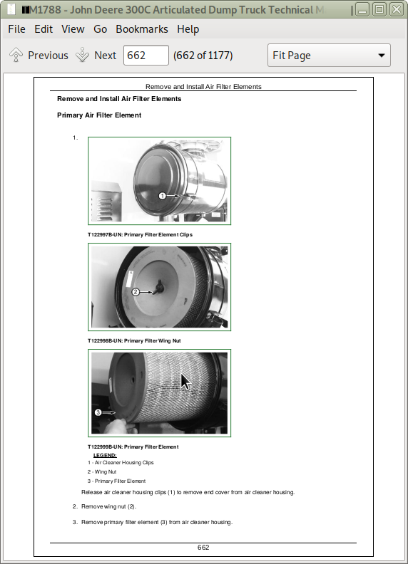
Remove and Install Air Filter Elements
Remove and Install Pre-Cleaner
Remove and Install Air Cleaner and Piping
Group 0530: External Exhaust Systems
Remove and Install Exhaust Muffler and Pipes
Remove and Install Exhaust Brake Valve
Remove and Install Exhaust Brake Air Cylinder
Remove and Install Body Heater Pipes
Group 0540: Engine Mounting
Specifications
Remove and Install Engine Mounts
Group 0560: External Fuel Supply Systems
Remove and Install Primary Fuel Filter (Water Separator) and Base
Remove and Install Secondary Fuel Filters and Base
Remove and Install Fuel Tank
Remove and Install Fuel Sender
Section 07: Dampener Drive
Group 0752: Elements
Service Equipment and Tools
Other Material
Specifications
Remove and Install Torsional Dampener
Section 09: Steering System
Group 0930: Secondary Steering
Specifications
Remove and Install Secondary Steering Pump Anti-Cavitation Valve
Remove and Install Secondary Steering Pump Anti-Cavitation Valve Block
Remove and Install Secondary Steering Pump
Disassemble and Assemble Secondary Steering Pump
Group 0960: Hydraulic System
Service Equipment and Tools
Other Material
Specifications
Remove and Install Steering Valve
Disassemble and Assemble Steering Valve
Remove and Install Steering Cylinder
Disassemble and Assemble Steering Cylinder
Disassemble and Assemble Steering Column
Section 10: Service Brakes
Group 1011: Active Elements
Other Material
Specifications
Bleed Service Brake Hydraulic System
Remove and Install Service Brake Pads
Remove and Install Service Brake Caliper
Disassemble and Assemble Service Brake Caliper
Remove and Install Brake Disk
Group 1060: Service Brake Hydraulic System
Essential Tools
Service Equipment and Tools
Remove and Install Hydraulic Brake Valve
Disassemble and Assemble Hydraulic Brake Valve
Remove and Install Rear Brake Accumulators
Remove and Install Front Brake Accumulators
Remove and Install Brake Accumulator
Section 11: Park Brake
Group 1111: Active Elements
Service Equipment and Tools
Specifications
Remove and Install Park Brake Pads
Remove and Install Park Brake Caliper
Remove and Install Park Brake Disk
Remove and Install Park Brake Valve
Remove and Install Park Brake Dump Valve
Section 16: Electrical System
Group 1671: Batteries, Support, and Cables
Service Equipment and Tools
Specifications
Prevent Acid Burns
Procedure for Testing Batteries
Check Battery Electrolyte Specific Gravity
Check Battery Electrolyte Level
Using Booster Batteries—24-Volt System
Remove and Install Batteries
Remove and Install Battery Balancer 24-Volt to 12-Volt Accessories
Remove and Install 12-Volt Circuit Breaker
Group 1672: Alternator, Regulator and Charging System Wiring
Specifications
Remove and Install Alternator
Group 1673: Lighting System
Remove and Install Headlights and Front Park Lights
Adjusting Headlights
Replace Front Turn Signal Bulb
Replace Tail Lights and Rear Turn Signals
Replace Backup Lights
Replace Dome Light Bulb
Group 1674: Wiring Harness and Switches
Service Equipment and Tools
Cab Harness (W5) Dash Panel Component Location
Cab Harness (W5) Breaker Panel Component Location
Replace DEUTSCH DEUTSCH is a trademark of the Deutsch Co. Connectors
Install DEUTSCH DEUTSCH is a trademark of the Deutsch Co. Contact
Replace WEATHER PACK WEATHER PACK is a trademark of Packard Electric. Connector
Install WEATHER PACK WEATHER PACK is a trademark of Packard Electric. Contact
Replace (Pull Type) METRI-PACK METRI-PACK is a trademark of Packard Electric. Connectors
Replace (Push Type) METRI-PACK METRI-PACK is a trademark of Packard Electric. Connectors
Remove Connector Body from Blade Terminals
Remove and Install Key Switch
Remove and Install Start Switch
Remove and Install Battery Disconnect Switch
Remove and Install Engine Oil Pressure Switch
Remove and Install Hydraulic Temperature Switch
Remove and Install Cold Start Temperature Sensor
Remove and Install Engine Coolant Temperature Sensor
Remove and Install Engine Coolant Level Sensor
Remove and Install Transmission Oil Temperature Switch
Remove and Install Transmission Kickdown Switch
Remove and Install Output Speed Sensor
Remove and Install Engine Speed Sensor
Remove and Install Internal Clutch Speed Sensor
Remove and Install Turbine Speed Sensor
Remove and Install Air Pressure Sensor
Remove and Install Low Air Pressure Switch
Remove and Install Steering Column Switch
Remove and Install Secondary Steering Pressure Switch
Remove and Install Brake Pressure Switch
Remove and Install Brake Light Switch
Remove and Install Park Brake Pressure Switch
Remove and Install Inter-Axle Lock Air Pressure Switch
Remove and Install Unloader Valve Switch
Remove and Install Right Control Panel Rocker Switches
Remove and Install Body Switch
Remove and Install Hydraulic Fan Motor Temperature Switch
Remove and Install Warning Buzzers
Remove and Install Transmission Lock-Up Valve Solenoid
Group 1675: System Controls
Welding Procedure
Remove and Install Transmission Control Unit
Remove and Install Transmission Shift Control
Remove and Install Display Monitor
Remove and Install Indicator Light Interface
Group 1676: Instruments and Indicators
Remove and Install Dash, Switches and Gauges
Replace Indicator Bulb
Replace Rocker Switch Indicator Bulbs
Group 1677: Motors and Actuators
Remove and Install Hydraulic Oil Cooler Fan
Remove and Install Starting Motor
Section 17: Frame and Supporting Structure
Group 1740: Frame Installation
Service Equipment and Tools
Specifications
Welding Repair of Major Structure
Oscillation Joint Bushings Inspect
Remove and Install Oscillation Joint Bushing
Adjust Oscillation Joint End Float
Replace Articulation Joint Bushings
Group 1746: Frame Bottom Guards
Service Equipment and Tools
Lower and Raise Bottom Guard
Section 18: Operator's Station
Group 1800: Removal and Installation
Specifications
Remove and Install Cab
Group 1810: Operator Enclosure
Service Equipment and Tools
Other Material
Remove and Install Cab Mounts
Remove and Install Cab Door and Latch Assembly
Remove and Install Windowpane and Molding
Windowpanes
Remove and Install Windshield Wiper Motor
Remove and Install Windshield Washer Reservoir
Remove and Install Windshield Washer Pump
Group 1821: Seat and Seat Belt
Remove and Install Air Suspension Seat
Remove and Install Air Seat Shock Absorber
Remove and Install Air Spring
Remove and Install Air Seat Switch
Remove and Install Seat Belt Assembly
Remove and Install Trainer Seat Belt Assembly
Remove and Install Arm Rest
Remove and Install Trainer Seat
Group 1822: Steps and Handholds
Remove and Install Right Step and Handhold
Remove and Install Left Steps and Handhold
Remove and Install Cab Rear Access Steps and Handholds
Group 1830: Heating and Air Conditioning
Essential Tools
Service Equipment and Tools
Other Material
Specifications
Proper R134a Refrigerant Handling
R134a Refrigerant Cautions
R134a Refrigerant Oil Charge Check
Compressor R134a Refrigerant Oil Removal
R134a Refrigerant Oil Component Charge
R134a Refrigerant Recovery/Recycling and Charging Station Installation
Recover R134a Refrigerant
Evacuate R134a Air Conditioner System
Charge R134a Air Conditioner System
Leak Testing R134a Air Conditioner System
R134A Air Conditioner System Cleaning Procedures
Purge R134a Air Conditioner System
Flush R134a Air Conditioner System
Heater and Air Conditioner Component Location
Remove and Install Air Conditioning and Heater Controls
Remove and Install Air Conditioning Compressor
Remove and Install Expansion Valve
Remove and Install Heater Valve Drive Module
Remove and Install Heater Valve
Remove and Install Heater Core
Remove and Install Fresh Air Vent Actuator
Remove and Install Air Conditioner Fresh Air Filter
Clean or Replace Air Conditioner Recirculating Filter
Remove and Install Receiver-Dryer
Remove and Install Condenser
Remove and Install Condenser Blower Motor
Remove and Install Blower Drive Module
Remove and Install Evaporator
Remove and Install Thermocouple
Remove and Install Blower Motor
Section 19: Sheet Metal and Styling
Group 1910: Hood or Engine Enclosure
Specifications
Remove and Install Hood
Remove and Install Hood Latch
Section 20: Safety and Convenience
Group 2002: Mirror
Remove and Install Mirror
Group 2004: Horn and Warning Devices
Remove and Install Horn
Remove and Install Reverse Warning Alarm
Section 21: Main Hydraulic System
Group 2160: Hydraulic System
Essential Tools
Service Equipment and Tools
Specifications
Remove and Install Hydraulic System Manifold
Disassemble and Assemble Hydraulic System Manifold
Remove and Install Hydraulic Cut-Off Solenoid Valve
Remove and Install Hydraulic Reservoir
Remove and Install Suction Screen
Remove and Install Hydraulic Reservoir Breather
Remove and Install Main Hydraulic Pump
Disassemble and Assemble Main Hydraulic Pump
Remove and Install Hydraulic Oil Cooler
Replace Hydraulic System Oil Return Filters
Section 22: Pneumatic Systems
Group 2261: Pumps and Drives Air Compressor
Other Material
Specifications
Remove and Install Air Compressor
Group 2262: Pneumatic Control Valves
Remove and Install Pneumatic System Air Dryer Filter
Remove and Install Unloader Valve with Air Dryer Assembly
Disassemble and Assemble Unloader Valve with Air Dryer Assembly
Remove and Install Leveling Valve and Linkage
Remove and Install Exhaust Brake Solenoid Valve
Remove and Install Inter-Axle Lock Solenoid Valve
Remove and Install Hydraulic Retarder Shuttle Valve
Remove and Install Air Flow Control Valve
Remove and Install Quick Release Valve
Remove and Install Hydraulic Retarder Control Valve
Remove and Install Accelerator Valve
Disassemble and Assemble Accelerator Valve
Remove and Install Engine Speed Actuator
Disassemble and Assemble Engine Speed Actuator
Group 2264: Reservoir, Filter, and Trap
Remove and Install Regeneration Air Reservoir
Remove and Install Air System Reservoir
Remove and Install Air Suspension Reservoir
Group 2265: Pneumatic Cylinders
Specifications
Remove and Install Air Spring
Adjust Front Suspension Height
Section 35: Haulage Device
Group 3540: Frames
Specifications
Remove and Install Body
Group 3560: Hydraulic System
Other Material
Specifications
Remove and Install Body Pilot Control Valve
Disassemble and Assemble Body Pilot Control Valve
Remove and Install Body Control Valve and Air Cylinder
Disassemble and Assemble Body Control Valve and Air Cylinder
Remove and Install Body Tilt Cylinder
Disassemble and Assemble Body Tilt Cylinder
Section 99: Dealer Fabricated Tools
Group 9900: Dealer Fabricated Tools
DFT1149 Clutch Pack Spring Compression Ring Tool
DFT1178 Lifting Tool
DFT1183 Rolling Drag Torque Bar
DFT1189 Spanner Wrench
DFT1190 Engine Mounting Adapter
DFT1197 Front Support
DFT1198 Oscillation Bushing Installation Tool
DFT1202 Lifting Bracket
John Deere 300C Articulated Dump Truck Repair Service Manual - TM1788
![]()