
John Deere Crawler Dozers / Loaders 450G, 455G, 550G, 555G, 650G Operation & Test Service Manual (TM1403)
Complete Operation & Test manual with electrical wiring diagrams for John Deere Crawler Dozers / Loaders 450G, 455G, 550G, 555G, 650G, with all the shop information to maintain, diagnose, and service like professional mechanics.
John Deere Crawler Dozers / Loaders 450G, 455G, 550G, 555G, 650G workshop Diagnostics & Test manual includes:
* Numbered table of contents easy to use so that you can find the information you need fast.
* Detailed sub-steps expand on repair procedure information
* Numbered instructions guide you through every repair procedure step by step.
* Troubleshooting and electrical service procedures are combined with detailed wiring diagrams for ease of use.
* Notes, cautions and warnings throughout each chapter pinpoint critical information.
* Bold figure number help you quickly match illustrations with instructions.
* Detailed illustrations, drawings and photos guide you through every procedure.
* Enlarged inset helps you identify and examine parts in detail.
tm1403 - 450G, 455G, 550G 555G, 650G Crawler Operation and Test Technical Manual.pdf
tm1403 - 450G, 455G, 550G 555G, 650G Crawler Operation and Test Technical Manual.epub
Total Pages: 902 pages
File Format: PDF (bookmarked, ToC, Searchable, Printable, high quality) & EPUB/MOBI/AZW for Kindle/iPad/iPhone/Android.
Language: English
MAIN SECTIONS
Foreword
Help!! Help!! Help!! Help!!
General Information
Safety Information
General Specifications
Torque Values
Fuels and Lubricants
Operational Checkout Procedure
Operational Checkout Procedure
Engine
Theory of Operation
System Operational Checks
System Diagnostic Information
Adjustments
Tests
Electrical System
System Information
System Diagrams
Sub-System Diagnostics
References
Power Train
Theory of Operation
System Operational Checks
Diagnostic Information
Adjustments
Tests
Hydraulic System
Theory of Operation
System Operational Checks
Diagnostic Information
Adjustments
Tests
Total Pages: 931 pages
File Format: PDF (bookmarked, ToC, Searchable, Printable, high quality)
Language: English
SECTION 9000—General Information
Group 01—Safety Information
Group 02—General Specifications
Group 03—Torque Values
Group 04—Fuels and Lubricants
9005
SECTION 9005—Operational Checkout Procedure
Group 10—Operational Checkout Procedure
SECTION 9010—Engine
Group 05—Theory of Operation
Group 10—System Operational Checks
Group 15—System Diagnostic Information
Group 20—Adjustments
Group 25—Tests
9010
9015
SECTION 9015—Electrical System
Group 05—System Information
Group 10—System Diagrams
Group 15—Sub-System Diagnostics
Group 20—References
9020
SECTION 9020—Power Train
Group 05—Theory of Operation
Group 10—System Operational Checks
Group 15—Diagnostic Information
Group 20—Adjustments
Group 25—Tests
9025
SECTION 9025—Hydraulic System
Group 05—Theory of Operation
Group 10—System Operational Checks
Group 15—Diagnostic Information
Group 20—Adjustments
Group 25—Tests
tm1403 - 450G, 455G, 550G 555G, 650G Crawler Operation and Test
Table of Contents
Foreword
Help!! Help!! Help!! Help!!
Section 9000: General Information
Group 01: Safety Information
Handle Fluids Safely-Avoid Fires
Prevent Battery Explosions
Prepare For Emergencies
Prevent Acid Burns
Handle Chemical Products Safely
Avoid High-Pressure Fluids
Park Machine Safely
Support Machine Properly
Wear Protective Clothing
Work In Clean Area
Service Machines Safely
Work In Ventilated Area
Illuminate Work Area Safely
Replace Safety Signs
Use Proper Lifting Equipment
Remove Paint Before Welding or Heating
Avoid Heating Near Pressurized Fluid Lines
Keep ROPS Installed Properly
Practice Safe Maintenance
Dispose of Waste Properly
Live With Safety
Group 02: General Specifications
450G Crawler Dozer Specifications
450G Drain and Refill Capacities
450G-LT Crawler Dozer Specifications
450G-LT Drain and Refill Capacities
450G-LGP Crawler Dozer Specifications
450G-LGP Drain and Refill Capacities
455G Crawler Loader Specifications
455G Operating Information
455G Drain and Refill Capacities
550G-LT Crawler Dozer Specifications
550G-LT Drain and Refill Capacities
550G-LGP Crawler Dozer Specifications
550G-LGP Drain and Refill Capacities
555G Crawler Loader Specifications
555G Drain and Refill Capacities
650G Crawler Dozer Specifications
650G Drain and Refill Capacities
650G-LGP Crawler Dozer Specifications
650G-LGP Drain and Refill Capacities
9310 Backhoe Specifications
9310 Backhoe Lift Capacity (G Series Loaders)
9310 Backhoe Lift Capacity (G-Series Dozers)
Group 03: Torque Values
Hardware Torque Specifications
Keeping ROPS Installed Properly
Checking Track Shoe Cap Screw Torque
Unified Inch Bolt and Cap Screw Torque Values
Metric Bolt and Cap Screw Torque Values
Additional Metric Cap Screw Torque Values
Check Oil Lines and Fittings
Service Recommendations for 37° Flare and 30° Cone Seat Connectors
Service Recommendations for O-Ring Boss Fittings
Service Recommendations for Flat Face O-Ring Seal Fittings
Service Recommendations for Inch Series Four Bolt Flange Fittings
Service Recommendations for Metric Series Four Bolt Flange Fitting
Group 04: Fuels and Lubricants
Fuel Specifications
Storing Fuel
Do Not Use Galvanized Containers
Diesel Engine Oil
Final Drive Oil
Track Roller, Front Idler, and Carrier Roller Oil
Transmission, Steering Clutches, Hydraulic and Winch Oil
Grease
Diesel Engine Coolant
Alternative and Synthetic Lubricants
Lubricant Storage
Section 9005: Operational Checkout Procedure
Group 10: Operational Checkout Procedure
Operational Checkout Procedure
Section 9010: Engine
Group 05: Theory of Operation
General Engine Description
Engine-Sectional View
Cold Weather Starting Aid Operation
Air Cleaner Operation
Group 10: System Operational Checks
4276 John Deere Engine-Use CTM4
4045 John Deere Engine-Use CTM8
John Deere PowerTech PowerTech is a registered trademark of Deere & Company 4045 Engine-Use CTM104
John Deere Engine Accessories-Use CTM11
System Operational Checks
Group 15: System Diagnostic Information
4276 John Deere Engine-Use CTM4
4045 John Deere Engine-Use CTM8
John Deere PowerTech PowerTech is a registered trademark of Deere & Company 4045 Engine-Use CTM104
John Deere Engine Accessories-Use CTM11
Make Visual Inspection of Engine and Supporting Systems
Diagnose Engine Malfunctions
Group 20: Adjustments
4276 John Deere Engine-Use CTM4
4045 John Deere Engine-Use CTM8
John Deere PowerTech PowerTech is a registered trademark of Deere & Company 4045 Engine-Use CTM104
JT07158 TIME TRAC TIME TRAC is a registered trademark of Standyne Automotive Corp. Installation
Fan V-Belt Tension Adjustment (S.N. -840460)
Fan Belt Tension Adjustment (S.N. 840461- )
Engine Speed Adjustment
Engine Speed Control Linkage Adjustment Without Declutch
Engine Speed Control Linkage Adjustment With Declutch
Injection Pump Dynamic Timing
Injection Pump Static Timing Adjustment
Group 25: Tests
4276 John Deere Engine-Use CTM4
4045 John Deere Engine-Use CTM8
John Deere PowerTech PowerTech is a registered trademark of Deere & Company 4045 Engine-Use CTM104
JT05801 Clamp-On Electronic Tachometer Installation
JT05800 Digital Thermometer Installation
Cooling System
Engine Oil Pressure Test
Fuel Supply Pump Pressure Test
Air Filter Restriction Indicator Switch Test
Air Intake System Leakage Test
Radiator Air Flow Test
Turbocharger Boost Pressure Test (S.N. -840460)
Turbocharger Boost Pressure Test (S.N. 840461- )
Section 9015: Electrical System
Group 05: System Information
Battery Operation
Battery Specifications
Diagnose Battery Malfunctions
Check Battery Electrolyte Level and Terminals
Procedure for Testing Batteries
Using Booster Batteries-12 Volt System
Visually Inspect Electrical System
Electrical Circuit Malfunctions
High Resistance Circuit
Open Circuit
Grounded Circuit
Shorted Circuit
Multimeter
Seven Step Electrical Test Procedure
Wiring Diagram and Schematic Information
Reading a System Functional Schematic
Reading a Wiring Diagram
Electrical Schematic Symbols
Group 10: System Diagrams
Component Identification Table
Circuit Breaker Specifications
Wiring and Schematic Diagrams Legend
System Functional Schematic Section Legend
System Functional Schematic
Front Console Harness (W5) Wiring Diagram-Modules
Front Console Harness (W5) Component Location-Modules
Front Console Harness (W5A) Wiring Diagram-Gauges
Front Console Harness (W5A) Component Location-Gauges
Engine Harness (W6) Wiring Diagram
Engine Harness (W6) Component Location
Rear Harness (W7) Wiring Diagram
Rear Harness (W7) Component Location
Return-to-Dig Harness (W8) Wiring Diagram
Return-to-Dig Harness (W8) Component Location
Work Light Harness (W9) Wiring Diagram
Work Light Harness (W9) Component Location
Horn Harness (W10) Wiring Diagram
Horn Harness (W10) Component Location
Declutch Harness (W11) Wiring Diagram
Declutch Harness (W11) Component Location
Cab Harness (W12) Wiring Diagram
Cab Harness (W12) Component Location
Pressurizer Harness (W13) Wiring Diagram
Pressurizer Harness (W13) Component Location
Blower Harness (W14) Wiring Diagram
Blower Harness (W14) Component Location
Roof Harness (W15) Wiring Diagram
Roof Harness (W15) Component Location
Group 15: Sub-System Diagnostics
Power Circuit Operational Information
Power Circuit Theory of Operation
Power Circuit Schematic
Start Circuit Operational Information
Start Circuit Theory of Operation
Start Circuit Schematic
Charging Circuit Operational Information
Charging Circuit Theory of Operation
Charge Circuit Schematic
Display Module and Logic Module Circuit Operational Information
Display Module and Logic Module Circuit Theory of Operation
Display Module and Logic Module Circuit Schematic
Logic Module
Indicator Circuit Specifications
Fuel Gauge Sender Specifications
Indicator Circuit Operational Information
Indicator Circuit Theory of Operation
Indicator Circuit Theory of Operation (Fuel Gauge)
Indicator Circuit Schematic
Indicator Circuit Schematic (Fuel Gauge)
Gauge Circuit Specifications
Gauge Circuit Operational Information
Gauge Circuit Theory of Operation
Gauge Circuit Schematic
Start Aid Circuit Operational Information
Start Aid Circuit Theory of Operation
Start Aid Circuit Schematic
Light Circuit Operational Information
Light Circuit Theory of Operation
Light Circuit Schematic
Horn Circuit Operational Information
Horn Circuit Theory of Operation
Horn Circuit Schematic
Reverse Alarm Circuit Operational Information
Reverse Alarm Circuit Theory of Operation
Reverse Alarm Circuit Schematic
Declutch Circuit Operational Information
Declutch Circuit Theory of Operation
Declutch Circuit Schematic
Return-to-Dig Circuit Operational Information
Return-to-Dig Circuit Theory of Operation
Return-to-Dig Circuit Schematic
Hourmeter Circuit Operational Information
Hourmeter Circuit Theory of Operation-with Modules
Hourmeter Circuit Theory of Operation-with Gauges
Hourmeter Circuit Schematic-with Modules
Hourmeter Circuit Schematic-with Gauges
Blower Circuit Operational Information
Blower Circuit Theory of Operation
Blower Circuit Schematic
Dome Light Circuit Operational Information
Dome Light Circuit Theory of Operation
Dome Light Circuit Schematic
Wiper/Washer Circuit Operational Information
Wiper/Washer Circuit Theory of Operation
Wiper/Washer Circuit Schematic
Group 20: References
John Deere Alternator and Starting Motors-Use CTM77
Alternator Operation-95 Amp Bosch
Alternator Operation-95 Amp Bosch
Logic Module Test in Machine
Logic Module Bench Test
Section 9020: Power Train
Group 05: Theory of Operation
Transmission Drive and Pump-Direct Drive
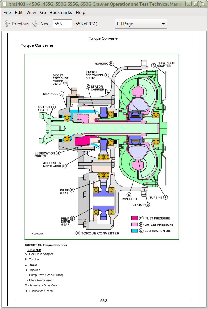
Torque Converter
Transmission Hydraulic Components-Direct Drive Machine (S.N. -803600)
Transmission Hydraulic Components-Direct Drive Machine (S.N. 803601- )
Transmission Hydraulic Components-Torque Converter Machine (S.N. -803600)
Transmission Hydraulic Components-Torque Converter Machine (S.N. 803601- )
Transmission-Thrust Washer/Bushing Design
Transmission-Ball Bearing Design
Power Flow-First Speed Forward
Power Flow-Second Speed Reverse
Transmission Oil Routing
Transmission Lubrication
Direction Clutch Pack
Speed Clutch Pack
Transmission Charge Circuit
Pressure Regulating Valve
Cooler and Lubrication Relief Valves
Speed Control Valve and Detent Spool
Speed Pack Orifices
Sump Valve Drain Port
Park Position
Steering Brake Control Linkage
Transmission Oil Flow-Direct Drive
Transmission Oil Flow-Torque Converter
Transmission Control Valve
Steering Brake Priority
Pedal Steering-Straight Travel
Pedal Steering-Right Steer
Pedal Steering-Both Pedals Depressed
Pedal Steering Linkage-(S.N. -770807)
Pedal Steering Linkage-(S.N. 770808- )
Lever Steering-Right Turn
Lever Steering-Both Levers Pulled
Lever Steering-(S.N. -770807)
Lever Steering-(S.N. 770808- )
Final Drives
Group 10: System Operational Checks
System Operational Procedure
Group 15: Diagnostic Information
Diagnose Transmission Malfunctions
Diagnose Undercarriage Malfunctions
Measure Track Bushing Outer Diameter
Measure Track Pitch-Sealed Chain
Measure Track Pitch for Lubricated Track Chain
Measure Grouser Bar Height
Measure Front Idler Wear
Measure Track Roller Wear
Measure Upper Track Carrier Roller Wear
Measure Link Height
Hydraulic Oil Filter Inspection Procedure
Group 20: Adjustments
Engage Tow Disconnect Pins Manually
Adjust Steering Brake Self-Adjuster Linkage-(S.N. -770807)
Manual Steering Brake Adjustment-(S.N. -770807)
Manual Steering Brake Adjustment-(S.N. 770808- )
Procedure for Complete Steering Adjustment
Loosen Brake Bands (S.N. -770807)
Loosen Brake Bands (S.N. 770808- )
Adjust Linkage Inside Transverse Housing
Adjust Stops-Pedal Steer
Adjust Linkage-Pedal Steer
Adjust Steering Valve-Pedal Steer-Direct Drive Machine (S.N. -770807)
Adjust Brakes
Adjust Steering Valve-Pedal Steer-Direct Drive Machine (S.N. 770808- )
Adjust Brakes
Adjust Steering Valve-Pedal Steer-Torque Converter Machine
Adjust Brakes
Adjust Stops-Lever Steer (S.N. -770807)
Adjust Stops-Lever Steer (S.N. 770808- )
Adjust Linkage-Lever Steer
Adjust Steering Valve-Lever Steer (S.N. -770807)
Adjust Brakes
Adjust Steering Valve-Lever Steer (S.N. 770808- )-Direct Drive Machine
Adjust Brakes
Adjust Steering Valve-Lever Steer-Torque Converter Machine
Adjust Brakes
Power Control Pedal Adjustment-Direct Drive Machine
Rate of Shift Adjustment
Transmission Control Linkage Adjustment
Declutch Switch Adjustment-Direct Drive Machine
Track Sag Adjustment
Idler Height Adjustment
Charge Transmission Accumulator-Direct Drive Machine
Group 25: Tests
JT05801 Clamp-On Electronic Tachometer Installation
JT05800 Digital Thermometer Installation
Transmission Air Test (In Transverse Housing)
Transmission Warm-Up Procedure-Direct Drive Machine
Transmission Pump Flow Test-Direct Drive Machine
Transmission Pressure Regulating Valve Test-Direct Drive Machine
Cooler Relief Valve Pressure Test-Direct Drive Machine
Lube Relief Valve Pressure Test-Direct Drive Machine
Steering Circuit Pressure Test-Direct Drive Machine
Complete Transmission System Test (S.N. -770807)-Direct Drive
Complete Transmission System Test Checkout Sheet (S.N. -770807)-Direct Drive
Complete Transmission System Test Specifications and Analysis (S.N. -770807)-Direct Drive
Complete Transmission System Test (S.N. 770808- )-Direct Drive
Complete Transmission System Test Checkout Sheet (S.N. 770808- )-Direct Drive
Complete Transmission System Test Specifications and Analysis (S.N. 770808- )-Direct Drive
Transmission and Steering Clutch Leakage Test Using Cooler Pressure (S.N. -770807)-Direct Drive
Transmission and Steering Clutch Leakage Chart Using Cooler Pressure (S.N. -770807)-Direct Drive
Analysis of Transmission and Steering Clutch Using Cooler Pressure (S.N. -770807)-Direct Drive
Transmission and Steering Clutch Leakage Test Using Cooler Pressure (S.N. 770808- )-Direct Drive
Transmission and Steering Clutch Leakage Chart Using Cooler Pressure (S.N. 770808- )-Direct Drive
Analysis of Transmission and Steering Clutch Test Using Cooler Pressure (S.N. 770808- )-Direct Drive
Transmission Oil Cooler Restriction Test-Direct Drive
Transmission Warm-Up Procedure-Torque Converter
Transmission Pump Flow Test-Torque Converter
Transmission Pressure Regulating Valve Test-Torque Converter
Cooler Relief and Converter-In Valve Pressure Test-Torque Converter
Lube Relief Valve Pressure Test-Torque Converter
Steering Circuit Pressure Test-Torque Converter
Complete Transmission System Test-Torque Converter
Complete Transmission System Test Checkout Sheet-Torque Converter
Transmission Complete System Test Specifications and Analysis-Torque Converter
Transmission and Steering Clutch Leakage Test Using Cooler Pressure-Torque Converter
Transmission and Steering Clutch Leakage Chart Using Cooler Pressure-Torque Converter
Analysis of Transmission and Steering Clutch Leakage Test Using Cooler Pressure-Torque Converter
Stall Speed Test-Torque Converter
Drain Leakage Test-Torque Converter
Transmission Oil Cooler Restriction Test-Torque Converter
Section 9025: Hydraulic System
Group 05: Theory of Operation
Dozer Hydraulic System Operation
Dozer Hydraulic System Operation
Loader Hydraulic System Operation
Hydraulic Reservoir Operation
Hydraulic Filter Operation
Hydraulic Pump Operation-Direct Drive
Hydraulic Pump Operation-Torque Converter
Dozer Blade Lift Valve Operation
Dozer Angle, Tilt, and Auxiliary Valve Operation
Dozer System Relief Valve Operation
Loader Control Valve Operation
Loader Valve Inlet Section Operation
Loader System Relief Valve Operation
Loader Bucket Dump Operation
Loader Bucket Regenerative Dump Operation
Loader Bucket Roll-back Operation
Loader Boom Raise Operation
Loader Boom Lower Operation
Loader Boom Float Operation
Loader Auxiliary Valve Operation
Hydraulic Cylinder Operation
Hydraulic Oil Cooler Operation
Group 10: System Operational Checks
System Operational Procedure
Group 15: Diagnostic Information
Use These Seven Basic Steps to Diagnose and Test the Hydraulic System
Make a Pretest Inspection and an Operation Check of the Machine
Hydraulic System Pretest
Hydraulic Oil Filter Inspection Procedure
Diagnose Hydraulic System Malfunction
Group 20: Adjustments
T-Bar Linkage Adjustment-(S.N. 763493- )
Return-to-Dig Adjustment
Group 25: Tests
JT05801 Clamp-On Electronic Tachometer Installation
JT05800 Digital Thermometer Installation
Hydraulic Oil Warm-Up Procedure
Main Hydraulic Pump Flow Test
Loader Circuit Relief Valve Test
Backhoe Circuit Relief Valve Test w/Flow Regulator-If Equipped (9300/9310)
Backhoe Circuit Relief Valve Test w/Remote Pump-If Equipped (9300/9310)
Hydraulic System Relief Valve Test
Cycle Time Test
Cylinder Drift Test
Cylinder Leakage Test
Hydraulic Oil Cooler Restriction Test
Component Location-Loader
Component Location-Dozer (S.N. -834560)
Component Location-Dozer (S.N. 834561- )
John Deere Crawler Dozers / Loaders 450G, 455G, 550G, 555G, 650G Operation & Test Service Manual (TM1403)
![]()