
John Deere Crawler Dozer 450G, 455G, 550G, 555G, 650G Repair Service Manual
Complete service repair manual for John Deere 450G, 455G, 550G, 555G, 650G Crawler Dozer, with all the workshop information to maintain, repair, and service like professional mechanics.
John Deere 450G, 455G, 550G, 555G, 650G Crawler Dozers workshop service repair manual includes:
* Numbered table of contents easy to use so that you can find the information you need fast.
* Detailed sub-steps expand on repair procedure information
* Numbered instructions guide you through every repair procedure step by step.
* Notes, cautions and warnings throughout each chapter pinpoint critical information.
* Bold figure number help you quickly match illustrations with instructions.
* Detailed illustrations, drawings and photos guide you through every procedure.
* Enlarged inset helps you identify and examine parts in detail.
TM1404 (EN) - John Deere 450G, 455G, 550G, 555G, 650G Crawler Dozer Technical Manual (Repair).PDF
TM1404 (EN) - John Deere 450G, 455G, 550G, 555G, 650G Crawler Dozer Technical Manual (Repair).epub
Total Pages: 981 pages
File Format: PDF (bookmarked, ToC, Searchable, Printable, high quality) & EPUB/MOBI/AZW for Kindle/iPad/iPhone/Android.
Language: English
MAIN SECTIONS
Foreword
Help!! Help!! Help!! Help!!
General Information
Safety Information
General Specifications
Torque Values
Fuels and Lubricants
Tracks
Track System
Dealer Fabricated Tools
Axles and Suspension Systems
Axle Shaft, Bearings, and Reduction Gears
Hydraulic System
Dealer Fabricated Tools
Transmission
Control Linkage
Input Drive Shafts and U-Joints
Gears, Shafts, Bearings and Clutch
Hydraulic System
Dealer Fabricated Tools
Engine
Removal and Installation
Engine Auxiliary Systems
Cold Weather Starting Aid
Cooling System
Speed Controls and Fuel Shut-Off Linkage
Intake System
External Fuel Supply System
Torque Converter
Removal and Installation
Turbine, Gears and Shaft
Dampener Drive
Removal and Installation
Steering Systems
Power Steering Linkage
Hydraulic System
Electrical System
Batteries, Support and Cables
Alternator, Regulator, and Charging System Wiring
Lighting System
Wiring Harness and Switches
Instruments and Indicators
Motors and Actuators
Frames, Chassis, or Supporting Structure
Frame Installation
Chassis Weights
Dealer Fabricated Tools
Operator`s Station
Removal and Installation
Seat and Seat Belt
Sheet Metal and Styling
Hood and Engine Enclosure
Miscellaneous Guards
Grille and Grille Housing
Fenders
Safety, Convenience and Miscellaneous
Horn and Warning Devices
Main Hydraulic System
Hydraulic System
Loader
Bucket
Controls Linkage
Frames
Hydraulics
Bulldozer
Blades
Controls Linkage
Frames
Hydraulic System
Backhoe
Removal and Installation
Backhoe
Buckets
Controls Linkage
Frames
Hydraulic System
Total Pages: 970 pages
File Format: PDF (bookmarked, ToC, Searchable, Printable, high quality)
Language: English
tm1404 - 450G, 455G, 550G, 555G, 650G Crawler
Table of Contents
Foreword
Help!! Help!! Help!! Help!!
Section 00: General Information
Group 0001: Safety Information
Handle Fluids Safely—Avoid Fires
Prevent Battery Explosions
Prepare for Emergencies
Prevent Acid Burns
Handle Chemical Products Safely
Avoid High-Pressure Fluids
Park Machine Safely
Support Machine Properly
Wear Protective Clothing
Work in Clean Area
Service Machines Safely
Work In Ventilated Area
Illuminate Work Area Safely
Replace Safety Signs
Use Proper Lifting Equipment
Remove Paint Before Welding or Heating
Avoid Heating Near Pressurized Fluid Lines
Keep ROPS Installed Properly
Service Tires Safely
Avoid Harmful Asbestos Dust
Practice Safe Maintenance
Use Proper Tools
Dispose of Waste Properly
Live With Safety
Group 0002: General Specifications
450G Crawler Dozer Specifications
450G Drain and Refill Capacities
450G—LT Crawler Dozer Specifications
450G—LT Drain and Refill Capacities
450G—LGP Crawler Dozer Specifications
450G—LGP Drain and Refill Capacities
455G Crawler Loader Specifications
455G Crawler Loader Specifications—cont.
455G Drain and Refill Capacities
550G—LT Crawler Dozer Specifications
550G—LT Drain and Refill Capacities
550G—LGP Crawler Dozer Specifications
550G—LGP Drain and Refill Capacities
555G Crawler Loader Specifications
555G Drain and Refill Capacities
650G Crawler Dozer Specifications
650G Drain and Refill Capacities
650G—LGP Crawler Dozer Specifications
650G—LGP Drain and Refill Capacities
9310 Backhoe Specifications
9310 Backhoe Lift Capacity (G Series Loaders)
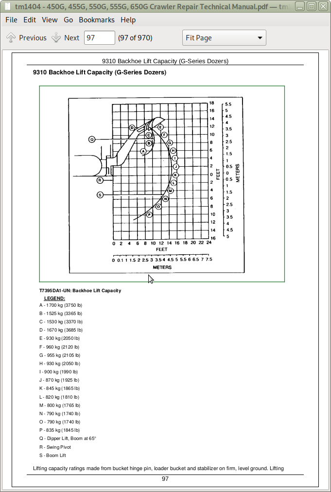
9310 Backhoe Lift Capacity (G-Series Dozers)
Group 0003: Torque Values
Specifications
Hardware Torque Specifications
ROPS Torque Specifications
Checking Track Shoe Cap Screw Torque
Unified Inch Bolt and Screw Torque Values
Metric Bolt and Screw Torque Values
Additional Metric Cap Screw Torque Values
Check Oil Lines And Fittings
Service Recommendations for 37° Flare and 30° Cone Seat Connectors
Service Recommendations for O-Ring Boss Fittings
Service Recommendations For Flat Face O-Ring Seal Fittings
Service Recommendations For Inch Series Four Bolt Flange Fittings
Service Recommendations for Metric Series Four Bolt Flange Fitting
Group 0004: Fuels and Lubricants
Fuel Specifications
Storing Fuel
Do Not Use Galvanized Containers
Diesel Engine Oil
Final Drive Oil
Track Roller, Front Idler, and Carrier Roller Oil
Transmission, Steering Clutches, Hydraulic and Winch Oil
Grease
Heavy Duty Diesel Engine Coolant
Alternative and Synthetic Lubricants
Lubricant Storage
Section 01: Tracks
Group 0130: Track System
Special or Essential Tools
Service Equipment and Tools
Other Material
Specifications
Measure Carrier Roller Wear
Remove and Install Carrier Roller Assembly
Disassemble and Assemble Carrier Roller
Check Carrier Roller Oil Level
Measure Track Roller Wear
Remove and Install Track Rollers
Disassemble and Assemble Track Roller (S.N. —XXXXXX)
Disassemble and Assemble Track Roller (S.N. XXXXXX— )
Checking Track Roller Oil Level (S.N. —XXXXXX)
Checking Track Roller Oil Level (S.N. XXXXXX— )
Adding Oil to the Roller (S.N. —XXXXXX)
Adding Oil to the Roller (S.N. XXXXXX— )
Measure Track Shoe Grouser Wear
Remove and Install Track Shoe
Measure Link Height
Measure Track Bushing Outer Diameter
Measure Track Pitch
Adjust Track Sag
Remove Sealed Track Chain
Turn Sealed Track Chain Pins and Bushings
Disassemble and Assemble Sealed Track Chain Using Track Press
Install Sealed Track Chain
Remove and Install Lubricated Track Chain—Interlock Master Link
Remove and Install Lubricated Track Chain—Single or Saw Tooth Master Split Link
Disassemble Lubricated Track Chain to Turn Bushings and Relubricate Chain
Assemble Lubricated Track Chain to Turn Bushings and Relubricate Chain
Disassemble and Assemble Lubricated Track Chain to Turn Pins and Not Relubricate
Measure Front Idler Wear
Remove and Install Front Idler Assembly
Disassemble and Inspect Front Idler Assembly
Assemble Front Idler Assembly
Idler Adjustment Procedure
Check Front Idler Oil Level
Remove and Disassemble Hydraulic Track Tension Adjuster (S.N. —745426)
Assemble and Install Hydraulic Track Tension Adjuster (S.N. —745426)
Remove and Disassemble Hydraulic Track Tension Adjuster (S.N. 745427—781708)
Remove and Disassemble Hydraulic Track Tension Adjuster (S.N. 781709— )
Assemble and Install Hydraulic Track Tension Adjuster (S.N. 745427—)
Remove and Install Track Idler Recoil Spring
Disassemble and Assemble Recoil Spring
Remove and Install Sprocket
Remove and Install Track Frame
Remove and Install Frame Wear Strips
Group 0199: Dealer Fabricated Tools
DF1041 Track Nut Removal Tool
DF1067 Lubricated Track Split Master Link Separator Tool—Earlier Machines
DFT1087 Track Recoil Spring Disassembly and Assembly Guard Tool
ST4920 Track Recoil Spring Disassembly and Assembly Tool
Section 02: Axles and Suspension Systems
Group 0250: Axle Shaft, Bearings, and Reduction Gears
Service Equipment and Tools
Other Material
Specifications
Remove and Install Final Drive
Disassemble and Assemble Final Drive
Adjust Pinion Shaft Preload
Adjust Idler Shaft Preload for Double Reduction Drives
Adjust Axle Shaft Preload
Remove and Install Steering Clutch
Disassemble and Assemble Steering Clutch (S.N. —770807)
Disassemble and Assemble Steering Clutch (S.N. 770808— )
Disassemble and Assemble Steering Brake Anchor (S.N. —770807)
Disassemble and Assemble Steering Brake Anchor (S.N. 770808— )
Disassemble and Assemble Steering Brake Linkage (S.N. —770807)
Disassemble and Assemble Steering Brake Linkage (S.N. 770808— )
Adjust Steering Brake Linkage
Adjust Steering Brake Self-Adjuster Linkage (S.N. —770807)
Manual Steering Brake Adjustment (S.N. —770807)
Manual Steering Brake Adjustment (S.N. 770808— )
Adjust Steering Brakes Linkage—Pedal Steer
Adjust Steering Brakes Linkage—Lever Steer (S.N. —770807)
Adjust Steering Brakes Linkage—Lever Steer (S.N. 770808—)
Engage Tow Disconnect Pins Manually
Group 0260: Hydraulic System
Other Material
Specifications
Remove and Install Steering Clutch Valve
Disassemble and Assemble Steering Clutch Valve (S.N. —770807)
Disassemble and Assemble Steering Clutch Valve (S.N. 770808— )
Adjust Steering Clutch Valve
Remove and Install Steering Brake Cylinder
Group 0299: Dealer Fabricated Tools
DF1030 Brake Assembly Tool
DF1063 Final Drive Lift Bracket
DF1063A Single Reduction Adapter Plate
DF1063B Double Reduction Adapter Plate
Section 03: Transmission
Group 0315: Control Linkage
Other Material
Specifications
Disassemble and Assemble Transmission Linkage (S.N. —768272)
Disassemble and Assemble Transmission Linkage (S.N. 768273— )
Transmission Control Linkage Adjustment
Group 0325: Input Drive Shafts and U-Joints
Remove and Install Drive Shaft
Group 0350: Gears, Shafts, Bearings and Clutch
Special or Essential Tools
Service Equipment and Tools
Other Material
Specifications
Remove and Install Transmission
Disassemble Transmission
Check Backing Plates Movement
Disassemble and Assemble Transmission Cover
Disassemble and Assemble First/Second and Third/Fourth Clutch Packs
Disassemble and Assemble Forward/Reverse Clutch Pack
Replace Ring Gear
Adjust Cone Point
Adjust Ring Gear Bearing Preload
Adjust Output Shaft Bearing Preload
Assemble Transmission
Transmission Air Test
Disassemble and Assemble Transverse Housing
Group 0360: Hydraulic System
Service Equipment and Tools
Other Material
Specifications
Remove and Install Transmission Control Valve
Disassemble and Assemble Transmission Control Valve
Disassemble and Assemble Transmission Control Valve Manifold
Adjust Rate of Shift
Disassemble and Assemble Transmission Decelerator Assembly
Remove and Install Transmission Oil Pump—Torque Converter Machines
Remove and Install Transmission Oil Pump—Direct Drive Machines
Disassemble and Assemble Transmission Oil Pump—Torque Converter Machines
Disassemble and Assemble Transmission Oil Pump—Direct Drive Machines
Charge Transmission Accumulator
Remove and Install Transmission Oil Filter
Remove and Install Transverse Case Suction Screen
Remove and Install Transmission Oil Cooler
Group 0399: Dealer Fabricated Tools
DF1126 Bearing Installer
DF1127 Support Tubing
DF1128 Bearing Installer
DF1031 Clutch Assembly Tool
DFT1121 Rivet Forming Tool
JT38000 Differential Lifting Tool
Section 04: Engine
Group 0400: Removal and Installation
4276 John Deere Engine Repair—Use CTM4 (S.N. —299999)
4045 John Deere Engine Repair—Use CTM8 (S.N. 300000—840460)
Engine Accessories—Use CTM11
PowerTech 4.5 L Engine Repair—Use CTM104 (S.N. 840461— )
Special or Essential Tools
Specifications
Remove Engine—With Torque Converter
Install Engine—With Torque Converter
Remove Engine—With Direct Drive
Install Engine—With Direct Drive
Bleed Fuel System
Section 05: Engine Auxiliary Systems
Group 0505: Cold Weather Starting Aid
Specifications
Other Material
Remove and Install Coolant Heater
Remove and Install Starting Aid Nozzle
Remove and Install Starting Aid Solenoid
Group 0510: Cooling System
Service Equipment and Tools
Specifications
Check and Adjust V-Belt Tension (S.N. —840460)
Checking Serpentine Belt Tensioner Spring Tension and Belt Wear (S.N. 840461— )
Remove and Install Sand Screens
Remove and Install Fan
Adjust Reversible Fan Blade Angle
Remove and Install Radiator
Group 0515: Speed Controls and Fuel Shut-Off Linkage
Remove and Install Speed Control Cable
Remove and Install Speed Control Linkage—Without Declutch
Remove and Install Speed Control Linkage—With Declutch
Group 0520: Intake System
Disassemble and Assemble Air Cleaner
Group 0560: External Fuel Supply System
Specifications
Remove and Install Fuel Tank
Section 06: Torque Converter
Group 0600: Removal and Installation
Special or Essential Tools
Other Material
Specifications
Remove and Install Torque Converter
Group 0651: Turbine, Gears and Shaft
Special or Essential Tools
Other Material
Specifications
Torque Converter Cross Section
Replace Torque Converter Rear Seal and Turbine Shaft
Disassemble and Assemble Torque Converter
Air Test Torque Converter
Disassemble and Assemble Torque Converter Housing
Section 07: Dampener Drive
Group 0700: Removal and Installation
Other Material
Specifications
Remove and Install Dampener Drive—Direct Drive Machines Only
Section 09: Steering Systems
Group 0920: Power Steering Linkage
Specifications
Remove and Install Steering Linkage—Pedal Steer
Adjust Stops—Pedal Steer
Adjust Linkage—Pedal Steer
Remove and Install Steering Linkage—Lever Steer
Adjust Stops—Lever Steer (S.N. —770807)
Adjust Stops—Lever Steer (S.N. 770808— )
Adjust Linkage—Lever Steer
Group 0960: Hydraulic System
Hydraulic System
Section 16: Electrical System
Group 1671: Batteries, Support and Cables
Specifications
Battery Safety
Check Battery Electrolyte Level and Terminals
Procedure for Testing Batteries
Using Booster Batteries—12-Volt System
Remove and Install Batteries
Group 1672: Alternator, Regulator, and Charging System Wiring
John Deere Engine Accessories—Use CTM11
Service Equipment and Tools
Specifications
Remove and Install Alternator
Group 1673: Lighting System
Replace Halogen Bulbs
Work Light Adjustment
Group 1674: Wiring Harness and Switches
Special or Essential Tools
Specifications
Replace DEUTSCH DEUTSCH is a trademark of the Deutsch Co. Connectors
Install DEUTSCH DEUTSCH is a trademark of the Deutsch Co. Contact
Replace WEATHER PACK WEATHER PACK is a trademark of Packard Electric. Connector
Install WEATHER PACK WEATHER PACK is a trademark of Packard Electric. Contact
Remove Connector Body from Blade Terminals
Remove and Install Battery Disconnect Switch
Remove and Install Transmission Low Pressure, Reverse Warning Alarm and Neutral Start Switches
Remove and Install Start Circuit Relay (S.N. —768317)
Remove and Install Start Circuit Relay (S.N. 768318— )
Remove and Install Return-to-Dig Switch
Remove and Install Return-to-Dig Switch Assembly
Return-to-Dig Adjustment
Group 1676: Instruments and Indicators
Remove and Install Logic Module or Circuit Breaker (S.N. —768317) (Module Package)
Remove and Install Logic Module or Circuit Breaker (S.N. 768318— ) (Module Package)
Remove and Install Display Monitor
Remove and Install Display Monitor Lights
Remove and Install Switch, Gauge, Hour Meter or Indicator Light
Group 1677: Motors and Actuators
John Deere Engine Accessories—Use CTM11
Remove and Install Starting Motor (S.N. —742459)
Remove and Install Starting Motor (S.N. 742460— )
Section 17: Frames, Chassis, or Supporting Structure
Group 1740: Frame Installation
Other Material
Specifications
Welding Repair of Major Structures
Remove and Install Transverse Housing
Group 1749: Chassis Weights
Service Equipment and Tools
Specifications
Remove and Install Sprocket Counterweight
Remove and Install Rear Counterweights
Remove and Install Front Counterweight
Group 1799: Dealer Fabricated Tools
JT38022 Sprocket Weight Lifting Tool
Section 18: Operator's Station
Group 1800: Removal and Installation
Other Material
Specifications
Remove and Install Roll-Over Protective Structure (ROPS) or Cab
Remove and Install ROPS/Cab Supports
Repair Foam Headliner
Group 1821: Seat and Seat Belt
Disassemble and Assemble Non-Suspension Seat
Disassemble and Assemble Deluxe Seat (ROPS)
Disassemble and Assemble Arm Rest
Exploded View of Suspension Seat
Section 19: Sheet Metal and Styling
Group 1910: Hood and Engine Enclosure
Other Material
Disassemble and Assemble Hood and Engine Side Shields
Disassemble and Assemble Cowl
Group 1913: Miscellaneous Guards
Remove and Install Bottom Guards and Access Covers
Group 1921: Grille and Grille Housing
Disassemble and Assemble Grille Housing
Group 1927: Fenders
Disassemble and Assemble Side Fenders
Disassemble and Assemble Back Fender (S.N. —763492)
Disassemble and Assemble Back Fender (S.N. 763493— )
Section 20: Safety, Convenience and Miscellaneous
Group 2004: Horn and Warning Devices
Remove and Install Horn
Remove and Install Reverse Warning Alarm—If Equipped
Adjust Reverse Warning Alarm Volume—If Equipped
Section 21: Main Hydraulic System
Group 2160: Hydraulic System
Other Material
Specifications
Remove and Install Hydraulic Pump and/or Drive Shaft—Direct Drive Machines
Disassemble and Assemble Hydraulic Pump—Direct Drive Machines
Remove and Install Hydraulic Pump—Torque Converter Machines
Disassemble and Assemble Hydraulic Pump—Torque Converter Machines
Remove and Install Hydraulic Oil Filter
Disassemble and Assemble Hydraulic Oil Filter
Remove and Install Hydraulic Oil Cooler
Remove and Install Hydraulic Reservoir
Section 31: Loader
Group 3102: Bucket
Specifications
Remove and Install Bucket Tooth Shanks
Remove and Install Bucket Tooth Tips
Remove and Install Loader Bucket
Repair Cracked Cutting Edge
Replace Cutting Edge
Group 3115: Controls Linkage
Other Material
Disassemble and Assemble Loader Control Linkage
Group 3140: Frames
Specifications
Remove Loader Boom
Install Loader Boom
Group 3160: Hydraulics
Other Material
Specifications
Loader Hydraulic Component Location
Remove and Install Loader Control Valve
Disassemble and Assemble Loader Control Valve
Disassemble and Assemble Bucket Section
Disassemble and Assemble Boom Section
Disassemble and Assemble Auxiliary Section
Cross Section of System Relief Valve
Inspect System Relief Valve
Inspect Anti-Cavitation Bucket Circuit Relief Valve
Inspect Bucket and Boom Adjusting Circuit Relief Valves
Disassemble and Inspect Boom and Bucket Cylinders
Cross Section of Bucket and Boom Cylinder
Assemble Boom and Bucket Cylinders
Disassemble and Assemble Ripper Cylinder
Section 32: Bulldozer
Group 3201: Blades
Other Material
Specifications
Remove and Install Dozer Blade (S.N. —785733)
Remove and Install Dozer Blade (S.N. 785734— )
Remove and Install Cutting Edges and End Bits
Group 3215: Controls Linkage
Other Material
Disassemble and Assemble Two Lever Control Linkage (S.N. —763492)
Disassemble and Assemble Two Lever Control Linkage (S.N. 763493— )
Disassemble and Assemble T-Bar Control Linkage (S.N. —763492)
Disassemble and Assemble T-Bar Control Linkage (S.N. 763493— )
Group 3240: Frames
Service Equipment and Tools
Remove and Install Dozer C-Frame
Disassemble and Assemble Blade Pitch Strut
Group 3260: Hydraulic System
Specifications
Dozer Hydraulic Component Location (S.N. —834560)
Dozer Hydraulic Component Location (S.N. 834561— )
Remove and Install Dozer Control Valve
Disassemble and Assemble Dozer Control Valve
Inspect System Relief Valve
Inspect Lift Checks
Disassemble and Assemble Angle, Tilt and Auxiliary Sections
Disassemble and Assemble Blade Section
Repair Cylinders
Section 33: Backhoe
Group 3300: Removal and Installation
Remove Backhoe Assembly
Install Backhoe Assembly
Group 3302: Buckets
Service Equipment and Tools
Remove and Install Bucket and Bucket Links
Remove and Install Bucket Bushings
Remove and Install Tooth Shank
Remove and Install Cutting Edges
Group 3315: Controls Linkage
Specifications
Remove, Install, and Adjust Backhoe Control Valve Linkage
Remove, Install, and Adjust Stabilizer Valve Linkage
Group 3340: Frames
Service Equipment and Tools
Other Material
Specifications
Remove and Install Dipperstick
Remove and Install Boom
Remove and Install Swing Frame
Remove and Install Stabilizer
Remove and Install Valve Box
Group 3360: Hydraulic System
Other Material
Specifications
Disassemble Bucket, Crowd, Boom, Swing and Stabilizer Cylinder
Cross Section of Bucket Cylinder—9300G, 9310G and Boom Cylinder—9300G
Cross Section of Boom Cylinder—9310G
Cross Section of Crowd Cylinder—9300G
Cross Section of Crowd Cylinder—9310G
Cross Section of Stabilizer Cylinder—9300G, 9310G
Cross Section of Swing Cylinder—9300G, 9310G
Assemble Bucket, Crowd, Boom, Swing and Stabilizer Cylinder
Remove and Install Backhoe Control Valve
Disassemble and Assemble Backhoe Control Valve
Disassemble and Assemble Circuit Relief Valve With Anti-Cavitation
Disassemble and Assemble Circuit Relief Valve
Disassemble and Assemble Crowd and Bucket Valve Section
Disassemble and Assemble Boom Valve Section
Disassemble and Assemble Swing Valve Section
Disassemble and Assemble Outlet Valve Section (With Low Pressure Regenerative Relief Valve)
Backhoe Relief Valve Specifications
Remove and Install Stabilizer Valve
Cross Section View of Stabilizer Control Valve
Disassemble Stabilizer Control Valve
Assemble Stabilizer Control Valve
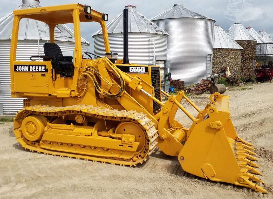
John Deere Crawler Dozer 450G, 455G, 550G, 555G, 650G Repair Service Manual (TM1404)
![]()