
John Deere Crawler Dozers 450H, 550H, 650H Service Repair Service Manual (TM1744)
Complete service repair manual for John Deere Crawler Dozers 450H, 550H, 650H, with workshop information to maintain, repair, and service like professional mechanics.
John Deere Crawler Dozers 450H, 550H, 650H workshop service repair manual includes:
* Numbered table of contents easy to use so that you can find the information you need fast.
* Detailed sub-steps expand on repair procedure information
* Numbered instructions guide you through every repair procedure step by step.
* Notes, cautions and warnings throughout each chapter pinpoint critical information.
* Bold figure number help you quickly match illustrations with instructions.
* Detailed illustrations, drawings and photos guide you through every procedure.
* Enlarged inset helps you identify and examine parts in detail.
TM1744 - John Deere 450H, 550H, 650H Crawler Dozers Technical Manual - Repair.pdf
TM1744 - John Deere 450H, 550H, 650H Crawler Dozers Technical Manual - Repair.epub
Total Pages: 930 pages
File Format: PDF/EPUB/MOBI/AZW (PC/Mac/Android/Kindle/iPhone/iPad; bookmarked, ToC, Searchable, Printable)
Language: English
MAIN SECTIONS
Foreword
Technical Information Feedback Form
General Information
Safety
General Specifications
Torque Values
Fuels and Lubricants
Tracks
Track System
Dealer Fabricated Tools
Axles and Suspension Systems
Drive Axle Housing and Support
Axle Shaft, Bearings, and Reduction Gear
Dealer Fabricated Tools
Transmission
Removal and Installation
Controls Linkage
Hydrostatic System
Dealer Fabricated Tools
Engine
Removal and Installation
Dealer Fabricated Tools
Engine Auxiliary Systems
Cold Weather Starting Aids
Radiator and Fan Shroud
Engine Speed Control
Intake System
External Exhaust System
Mounting Frame
External Fuel Supply System
Dampener Drive
Elements
Park Brake
Removal and Installation
Control Linkage
Hydraulic System
Equipment Attaching
Drawbar
Electrical System
Batteries, Support, and Cables
Alternator, Regulator and Charging System Wiring
Wiring Harness and Switches
System Controls
Instruments and Indicators
Motors and Actuators
Frames, Chassis, or Supporting Structure
Frame Installation
Chassis Weights
Operator`s Station
Removal and Installation
Operator`s Enclosure
Seat and Seat Belt
Heating and Air Conditioning
Dealer Fabricated Tools
Sheet Metal and Styling
Hood and Engine Enclosure
Grille and Grille Housing
Safety, Convenience and Miscellaneous
Horn and Warning Devices
Main Hydraulic System
Hydraulic System
Dealer Fabricated Tools
Bulldozer
Blades
Control Linkage
Frames
Hydraulic System
tm1744 - 450H, 550H, 650H Crawler Dozer
Table of Contents
Foreword
Technical Information Feedback Form
Section 00: General Information
Group 01: Safety
Recognize Safety Information
Follow Safety Instructions
Operate Only If Qualified
Wear Protective Equipment
Avoid Unauthorized Machine Modifications
Inspect Machine
Stay Clear of Moving Parts
Avoid High-Pressure Fluids
Beware of Exhaust Fumes
Prevent Fires
Prevent Battery Explosions
Handle Chemical Products Safely
Dispose of Waste Properly
Prepare for Emergencies
Add Cab Guarding For Special Uses
Start Only From Operator's Seat
Prevent Unintended Machine Movement
Avoid Work Site Hazards
Keep Riders Off Machine
Avoid Backover Accidents
Avoid Machine Tip Over
Park And Prepare For Service Safely
Service Cooling System Safely
Remove Paint Before Welding or Heating
Make Welding Repairs Safely
Drive Metal Pins Safely
Safety Signs
Instrument Panel with Gauge Package—If Equipped (Earlier Machines)
Instrument Panel Functions (Earlier Machines)
Instrument Panel (Later Machines)
Instrument Panel Functions (Later Machines)
Transmission Controller Display Window
Air Conditioning and Cab Heater—If Equipped
Windshield Wiper and Washer Controls
Windshield Washer Reservoir
Horn Switch
Auxiliary Power Outlet—If Equipped
Side Windows—Secondary Exits
Adjust Non-Suspension Seat
Adjust Suspension Seat—If Equipped
Adjust Armrest
Seat Belt
Live With Safety
Group 02: General Specifications
450H and 450H-LT Crawler Dozer Dimensions
450H-LGP Crawler Dozer Dimensions
450H Crawler Dozer Specifications
450H Other Information
450H Crawler Dozer Weights
450H Crawler Dozer Drain and Refill Capacities
550H Crawler Dozer Dimensions
550H Crawler Dozer Specifications
550H Crawler Dozer Weights
550H-LGP Crawler Dozer Dimensions
550H-LGP Crawler Dozer Specifications
550H-LGP Crawler Dozer Weights
550H and 550H-LGP Other Information
550H and 550H-LGP Crawler Dozer Drain and Refill Capacities
650H Crawler Dozer Dimensions
650H Crawler Dozer Specifications
650H Crawler Dozer Weights
650H-LGP Crawler Dozer Dimensions
650H-LGP Crawler Dozer Specifications
650H-LGP Crawler Dozer Weights
650H and 650H-LGP Other Information
650H and 650H-LGP Crawler Dozer Drain and Refill Capacities
Maximum Cable Capacities
Group 03: Torque Values
Hardware Torque Specifications
Keeping ROPS Installed Properly
Checking Track Shoe Cap Screw Torque
Unified Inch Bolt and Screw Torque Values
Metric Bolt and Screw Torque Values
Additional Metric Cap Screw Torque Values
Check Oil Lines And Fittings
O-Ring Groove Connections
Service Recommendations For Flat Face O-Ring Seal Fittings
Service Recommendations for O-Ring Boss Fittings
Service Recommendations for Inch Series Four Bolt Flange Fittings
Service Recommendations for Metric Series Four Bolt Flange Fitting
Group 04: Fuels and Lubricants
Diesel Fuel
Low Sulfur Diesel Fuel Conditioner
Diesel Fuel Storage
Fuel Tank
Diesel Engine Oil
Track Rollers, Front Idler and Carrier Roller Oil
Transmission and Hydraulic Oil
Winch Oil
Inner and Outer Final Drive Oil
Grease
Lubricant Storage
Alternative and Synthetic Lubricants
Mixing of Lubricants
Heavy Duty Diesel Engine Coolant
Section 01: Tracks
Group 0130: Track System
Essential Tools
Service Equipment and Tools
Other Material
Specifications
Remove and Install Rock Guards and Chain Guides
Measure Carrier Roller Wear
Remove and Install Carrier Roller Assembly
Disassemble and Assemble Carrier Roller
Inspect Carrier Roller Metal Face Seals
Check Carrier Roller Oil Level
Measure Track Roller Wear
Remove and Install Track Roller
Disassemble and Assemble Track Roller
Check Track Roller Oil Level
Adding Oil to The Roller
Test Track Roller for Leakage
Inspect Track Roller Metal Face Seals
Measure Track Shoe Grouser Wear
Remove and Install Track Shoe
Measure Link Height
Measure Track Bushing Outer Diameter
Measure Track Pitch
Check Track Sag
Adjust Track Sag
Remove Sealed Track Chain
Turn Sealed Track Chain Pins and Bushings
Disassemble and Assemble Sealed Track Chain Using Track Press
Install Sealed Track Chain
Remove and Install Lubricated Track Chain—Saw Tooth Master Split Link
Disassemble Lubricated Track Chain to Turn Bushings and Lubricate Chain
Assemble Lubricated Track Chain to Turn Bushings and Lubricate Chain
Disassemble and Assemble Lubricated Track Chain to Turn Pins and Not Lubricate
Measure Front Idler Wear
Remove and Install Front Idler
Disassemble, Inspect, and Assemble Front Idler
Idler Adjustment Procedure
Check Front Idler Oil Level
Remove and Disassemble Hydraulic Track Tension Adjuster
Assemble and Install Hydraulic Track Tension Adjuster
Remove and Install Track Idler Recoil Spring
Disassemble and Assemble Recoil Spring
Remove and Install Sprocket
Remove and Install Track Frame
Remove and Install Frame Wear Strips
Group 0199: Dealer Fabricated Tools
DF1041 Track Nut Removal Tool
DFT1087 Track Recoil Spring Disassembly and Assembly Guard Tool
ST4920 Track Recoil Spring Disassembly and Assembly Tool
Section 02: Axles and Suspension Systems
Group 0201: Drive Axle Housing and Support
Service Equipment and Tools
Other Material
Specifications
Remove and Install Final Drive
Group 0250: Axle Shaft, Bearings, and Reduction Gear
Essential Tools
Other Material
Specifications
Disassemble and Assemble Final Drive
Group 0299: Dealer Fabricated Tools
DF1063 Final Drive Lift Bracket
DFT1166 Final Drive Lifting Bracket Adapter
DFT1167 Final Drive Lifting Bracket Adapter Spacer
Section 03: Transmission
Group 0300: Removal and Installation
Service Equipment and Tools
Other Material
Specifications
Hydrostatic Component Location
Remove and Install Hydrostatic Pump
Remove and Install Hydrostatic Motors
Group 0315: Controls Linkage
Essential Tools
Other Material
Specifications
Single Lever Control (SLC) Exploded View (With Speed Lever, If Equipped)
Single Lever Control (SLC) Exploded View (With Speed In Grip, If Equipped)
Remove and Install Single Lever Control (SLC) (With Speed Lever, If Equipped)
Remove and Install Single Lever Control (SLC) (With Speed In Grip, If Equipped)
Disassemble and Assemble Single Lever Control Linkage (SLC)
Remove and Install Transmission Speed Lever Assembly (If Equipped)
Disassemble and Assemble Transmission Speed Lever Assembly (If Equipped)
Group 0360: Hydrostatic System
Essential Tools
Service Equipment and Tools
Specifications
Hydrostatic Pump Exploded View
Disassemble Hydrostatic Pumps
Charge Pump and Pump Controls Exploded View
Disassemble and Assemble Hydrostatic Charge Pump
Pump Displacement Control Valve (PDCV) Remove and Install
Disassemble and Assemble Displacement Control Valve
Disassemble and Assemble Multi-Function Valve
Disassemble and Assemble Neutral Charge Relief Valve
Assemble Hydrostatic Pump
Remove and Install Hydrostatic Motor Speed Sensor
Adjust Hydrostatic Motor Speed Sensor
Disassemble Hydrostatic Motor
Disassemble and Assemble Motor Shift Solenoid Valve
Disassemble and Assemble Charge Pressure Relief Valve
Disassemble and Assemble Loop Flushing Valve
Assemble Hydrostatic Motor
Remove and Install Oil Cooler Thermal Bypass Valve
Disassemble and Assemble Oil Cooler Thermal Bypass Valve
Remove and Install Hydrostatic Filter
Disassemble and Assemble Hydrostatic Filter
Remove and Install Hydrostatic Reservoir
Remove and Install Diagnostic Plumbing
Group 0399: Dealer Fabricated Tools
DFT1063 Pump Lifting Bracket
DFT1130 Adapter
DFT1132 Hydrostatic Motor Removal and Installation Tool
DFT1165 Left Hand Hydrostatic Motor Lifting Bracket
DFT1168 Right Hand Hydrostatic Motor Lifting Bracket
Section 04: Engine
Group 0400: Removal and Installation
Service Equipment and Tools
Other Material
Specifications
POWERTECH POWERTECH is a trademark of Deere & Company 4.5L (4045) John Deere Engines
Remove and Install Engine (450H, 550H S.N. —910011) (650H S.N. —924717)
Remove and Install Engine (450H, 550H S.N. 910011—) (650H S.N. 924718—)
Bleed Fuel System
Group 0499: Dealer Fabricated Tools
DFT1119 Pump Support
Section 05: Engine Auxiliary Systems
Group 0505: Cold Weather Starting Aids
Specifications
PowerTech PowerTech is a registered trademark of Deere & Company 4.5L (4045) John Deere Engine—Use CTM104
Remove and Install Engine Coolant Heater
Remove and Install Starting Aid—If Equipped
Remove and Install Starting Aid Solenoid—If Equipped
Group 0510: Radiator and Fan Shroud
Other Material
Specifications
Remove and Install Fan Blade and Shroud (450H, 550H) (650H S.N.—924717)
Remove and Install Fan Blade and Shroud (650H S.N 924718— )
Remove Radiator and Oil Cooler (450H, 550H) (650H S.N.—924717)
Install Radiator and Oil Cooler (450H, 550H) (650H S.N.—924717)
Cooling Package Remove and Install (650H S.N. 924718— )
Remove and Install Sand Shield—If Equipped
Group 0515: Engine Speed Control
Other Material
Specifications
Remove and Install Engine Speed Control and Decelerator
Group 0520: Intake System
Specifications
Remove and Install Air Cleaner with Turbocharger or Naturally Aspirated 450H, (550H and 650H S. N. —893112)
Remove and Install Air Cleaner 550H and 650H (S.N. 893113 — )
Group 0530: External Exhaust System
Specifications
Remove and Install Muffler Without Turbocharger
Remove and Install Muffler With Turbocharger
Group 0540: Mounting Frame
Specifications
Engine and Power Train Mounting
Group 0560: External Fuel Supply System
Specifications
Remove and Install Fuel Tank
Section 07: Dampener Drive
Group 0752: Elements
Other Material
Specifications
Remove and Install Dampener Drive
Section 11: Park Brake
Group 1100: Removal and Installation
Other Material
Remove and Install Brake Valve
Remove and Install Park Brake
Group 1115: Control Linkage
Service Equipment and Tools
Other Material
Specifications
Remove and Install Brake Pedal Control Linkage
Remove and Install Park Lock Linkage
Group 1160: Hydraulic System
Other Material
Specifications
Disassemble and Assemble Brake Valve
Disassemble and Assemble Park Brake
Section 15: Equipment Attaching
Group 1511: Drawbar
Remove and Install Drawbar
Remove and Install Tow Hook
Section 16: Electrical System
Group 1671: Batteries, Support, and Cables
Service Equipment and Tools
Specifications
Battery Safety
Service Batteries Carefully
Procedure for Testing Batteries
Check Battery Electrolyte Specific Gravity
Check Battery Electrolyte Level
Using Booster Batteries—12—Volt System
Remove and Install Batteries
Group 1672: Alternator, Regulator and Charging System Wiring
Specifications
Alternators and Starting Motors—Use CTM77
Remove and Install Alternator
Group 1674: Wiring Harness and Switches
Essential Tools
Service Equipment and Tools
Cab and ROPS Component Location 1 of 8
Engine Harness Component Location
Transmission Harness Component Location
Radio Harness (W9) Component Location
Air Conditioning and Heater Harness Component Location
Explanation Of Wire Markings
Fuse and Relay Color Codes
Replace DEUTSCH DEUTSCH is a trademark of Deutsch Co. Connector
Install DEUTSCH DEUTSCH is a trademark of Deutsch Co. Contact
Replace WEATHER PACK WEATHER PACK is a trademark of Packard Electric. Connectors
Install WEATHER PACK WEATHER PACK is a trademark of Packard Electric. Contact
Replace (Pull Type) Metri-Pack™ Connectors
Replace (Push Type) Metri-Pack™ Connectors
Remove Connector Body from Blade Terminals
Group 1675: System Controls
Specifications
Welding Procedure
Remove and Install Transmission Controller
Remove and Install Display Monitor
Group 1676: Instruments and Indicators
Remove and Install Dash, Switches and Gauges
Group 1677: Motors and Actuators
John Deere Starting Motor—Use CTM77
Remove and Install Starting Motor
Section 17: Frames, Chassis, or Supporting Structure
Group 1740: Frame Installation
Specifications
Welding Repair of Major Structure
Remove and Install Frame and Bottom Guards
Remove and Install Pivot Shafts
Remove and Install Crossbar
Group 1749: Chassis Weights
Remove and Install Counterweight
Section 18: Operator's Station
Group 1800: Removal and Installation
Service Equipment and Tools
Specifications
Remove Cab or ROPS
Install Cab or ROPS
Group 1810: Operator's Enclosure
Remove and Install Slide Glass
Remove and Install Stationary Glass
Remove and Install Windowpanes
Remove and Install Front Window Wiper
Remove and Install Door Window Wipers (Left Shown)
Remove and Install Window Washer Pumps
Group 1821: Seat and Seat Belt
Remove and Install Standard Seat
Remove and Install Deluxe Seat
Remove and Install Air Suspension Seat
Group 1830: Heating and Air Conditioning
Essential Tools
Service Equipment and Tools
Other Material
Specifications
R134a Refrigerant Theory of Operation
Proper Refrigerant Handling
R134a Refrigerant Cautions
R134a Compressor Oil Charge Check
R134a Compressor Oil Removal
R134a Component Oil Charge
R134a Refrigerant Recovery, Recycling and Charging Station Installation Procedure
Recover R134a System
Evacuate R134a System
Charge R134a System
Leakage Testing
Air Conditioner System Cleaning Procedures
Purge Air Conditioner System
Flush Air Conditioner System
Air Conditioning Electrical and Component Location
Air Conditioning Electrical and Component Location—Continued
Remove and Install Compressor
Disassemble and Assemble Compressor Clutch
Check Clutch Hub Clearance
Inspect Compressor Manifold
Disassemble, Inspect and Assemble Compressor
Remove and Install Receiver-Dryer
Remove and Install Evaporator or Heater Core
Remove and Install Expansion Valve
Remove and Install Condenser
Remove and Install A/C Freeze Switch
Remove and Install Upper Cab Heater Blower Motor or Heater Blower Resistor
Disassemble and Assemble Cab Upper Heater
Disassemble and Assemble Cab or ROPS Under Seat Heater
Group 1899: Dealer Fabricated Tools
DFRW20 Compressor Holding Fixture
Section 19: Sheet Metal and Styling
Group 1910: Hood and Engine Enclosure
Specifications
Remove and Install Hood
Remove and Install Hood Support and Engine Side Shields
Group 1921: Grille and Grille Housing
Specifications
Remove Grille and Grille Housing
Install Grille and Grille Housing
Section 20: Safety, Convenience and Miscellaneous
Group 2004: Horn and Warning Devices
Remove and Install Reverse Warning Alarm
Adjust Reverse Warning Alarm Volume
Section 21: Main Hydraulic System
Group 2160: Hydraulic System
Service Equipment and Tools
Specifications
Remove and Install Hydraulic Pump
Disassemble and Assemble Hydraulic Pump (With Winch Option)
Disassemble and Assemble Hydraulic Pump (Without Winch Option)
Remove and Install Hydraulic Reservoir
Hydraulic Reservoir (S.N. 925789— ) And Hydrostatic Reservoir (S.N. 925855— ) Cleanout Cover Remove and Install
Disassemble and Assemble Hydraulic Reservoir
Remove and Install Hydraulic Filter
Disassemble and Assemble Hydraulic Filter
Group 2199: Dealer Fabricated Tools
DFT1132 Hydrostatic Motor and Hydraulic Pump Removal and Installation Tool
Section 32: Bulldozer
Group 3201: Blades
Specifications
Remove and Install Dozer Blade (S.N. —903158)
Remove and Install Dozer Blade (S.N. 903159— )
Remove and Install Cutting Edges and End Bits
Group 3215: Control Linkage
Specifications
Remove and Install T-Bar Control Linkage
Remove and Install Auxiliary Linkage
Group 3240: Frames
Specifications
Remove and Install Dozer C-Frame (S.N. —903158)
Remove and Install Dozer C-Frame (S.N. 903159— )
Group 3260: Hydraulic System
Essential Tools
Service Equipment and Tools
Other Material
Specifications
Hydraulic System Component Location
Remove and Install Hydraulic Control Valve
Disassemble and Assemble Hydraulic Control Valve
Remove and Install Wiper Seals and Lip Seals on Hydraulic Control Valve Sections
Disassemble and Assemble Auxiliary Control Valve Section
Disassemble and Assemble Angle Control Valve Section (S.N. —902404)
Disassemble and Assemble Angle Control Valve Section (S.N. 902405— )
Disassemble and Assemble Tilt Control Valve Section
Disassemble and Assemble Lift Control Valve Section
Disassemble and Assemble System and Angle Circuit Relief Valve
Tilt Cylinder-To-Control Valve Component Location
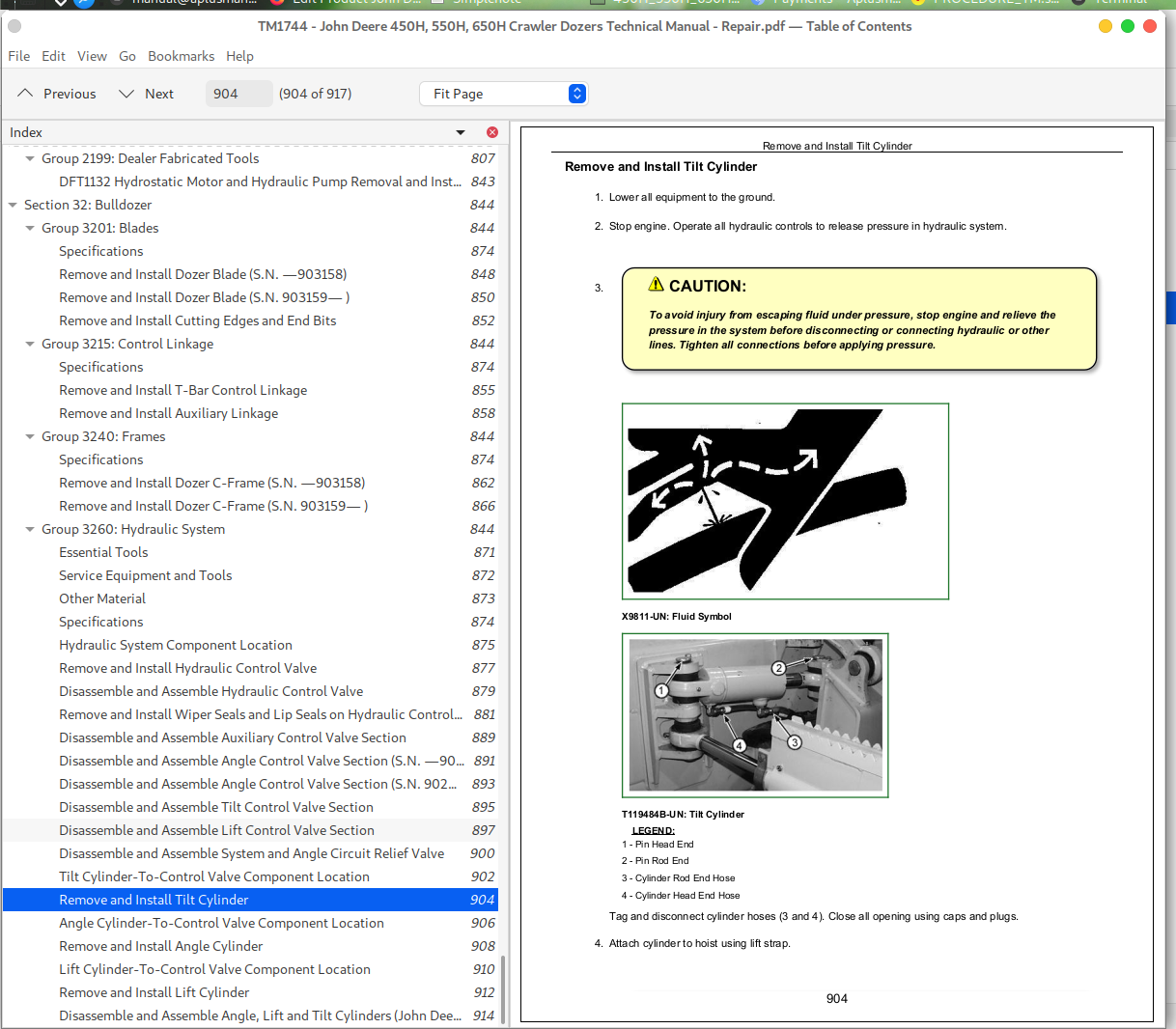
Remove and Install Tilt Cylinder
Angle Cylinder-To-Control Valve Component Location
Remove and Install Angle Cylinder
Lift Cylinder-To-Control Valve Component Location
Remove and Install Lift Cylinder
Disassemble and Assemble Angle, Lift and Tilt Cylinders (John Deere 120 Series Cylinders)
John Deere Crawler Dozers 450H, 550H, 650H Service Repair Service Manual (TM1744)
![]()