
John Deere Crawler Dozer 450J, 550J, 650J Operation & Test Service Manual (TM10721)
Complete Operation & Test manual with Electrical Wiring Diagrams for John Deere Crawler Dozer 450J, 550J, 650J (S.N. 159987-XXXXXX), with workshop information to maintain, diagnose, and rebuild like professional mechanics.
John Deere Crawler Dozer 450J, 550J, 650J workshop Diagnostics & Test manual includes:
* Numbered table of contents easy to use so that you can find the information you need fast.
* Detailed sub-steps expand on repair procedure information
* Numbered instructions guide you through every repair procedure step by step.
* Troubleshooting and electrical service procedures are combined with detailed wiring diagrams for ease of use.
* Notes, cautions and warnings throughout each chapter pinpoint critical information.
* Bold figure number help you quickly match illustrations with instructions.
* Detailed illustrations, drawings and photos guide you through every procedure.
* Enlarged inset helps you identify and examine parts in detail.
TM10721 - John Deere 450J, 550J, 650J Crawler Dozer Technical Manual - Operation & Test.PDF
TM10721 - John Deere 450J, 550J, 650J Crawler Dozer Technical Manual - Operation & Test.epub
Total Pages: 1,130 pages
File Format: PDF/EPUB/MOBI/AZW (PC/Mac/Android/Kindle/iPhone/iPad; bookmarked, ToC, Searchable, Printable)
Language: English
MAIN SECTIONS
Foreword
Technical Information Feedback Form
General Information
Safety
Diagnostic Trouble Codes (DTC)
Standard Display Monitor (SDM) Diagnostic Trouble Codes
Engine Control Unit (ECU) Diagnostic Trouble Codes
Transmission Control Unit (TCU) Diagnostic Trouble Codes
Electrohydraulic Controller (EHC) Diagnostic Trouble Codes
Blade Control Joystick (BCJ) Diagnostic Trouble Codes
Operational Checkout Procedure
System Operational Checks
Engine
Theory Of Operation
Diagnostic Information
Tests
Electrical System
System Information
System Diagrams
Sub-System Diagnostics
Monitor Operation
References
Hydraulic System
Theory of Operation
tm10721 - 450J (SN 159987—216242), 550J, 650J (SN 159987— )Crawler Dozer
Table of Contents
Foreword
Technical Information Feedback Form
Section 9000: General Information
Group 01: Safety
Recognize Safety Information
Follow Safety Instructions
Operate Only If Qualified
Wear Protective Equipment
Avoid Unauthorized Machine Modifications
Inspect Machine
Stay Clear of Moving Parts
Avoid High-Pressure Fluids
Avoid High-Pressure Oils
Beware of Exhaust Fumes
Prevent Fires
Prevent Battery Explosions
Handle Chemical Products Safely
Dispose of Waste Properly
Prepare for Emergencies
Add Cab Guarding For Special Uses
Start Only From Operator's Seat
Prevent Unintended Machine Movement
Avoid Work Site Hazards
Keep Riders Off Machine
Avoid Backover Accidents
Avoid Machine Tip Over
Prevent Unintended Detonation of Explosive Devices
Park And Prepare For Service Safely
Service Cooling System Safely
Remove Paint Before Welding or Heating
Make Welding Repairs Safely
Drive Metal Pins Safely
Section 9001: Diagnostic Trouble Codes (DTC)
Group 10: Standard Display Monitor (SDM) Diagnostic Trouble Codes
Standard Display Monitor (SDM) Diagnostic Trouble Codes
000096.03 - Fuel Level Sender Open or Short
000096.04 - Fuel Level Sender Short to Gnd
000107.03 - Eng Air Filter Short to Power
000107.04 - Eng Air Filter Restricted
000177.03 - Trans Oil Temp Open or Short to Power
000177.04 - Trans Oil Temp Short to Gnd
000177.16 - Transmission Oil Temperature High
000609.09 - CAN Comm No TCU Msg
001638.00 - Hydraulic Oil High Temp
001638.03 - Hydraulic Oil Temp Short to Power
001638.04 - Hydraulic Oil Temp Short to Gnd
001713.31 - Hydraulic Oil Filter Restricted
002000.09 - CAN Comm No ECU Config
003156.09 - CAN Blade Mode Missing From EHC
003359.31 - Trans Oil Filter Restricted
Group 20: Engine Control Unit (ECU) Diagnostic Trouble Codes
Engine Control Unit (ECU) Diagnostic Trouble Codes
000091.09 - CAN Throttle Missing from TCU
Group 30: Transmission Control Unit (TCU) Diagnostic Trouble Codes
Transmission Control Unit (TCU) Diagnostic Trouble Codes
000070.00 - Park Lock Lever Inputs Both On
000070.01 - Park Lock Lever Inputs Both Off
000091.00 - Throttle Sensor Input Greater Than Max Cal
000091.01 - Throttle Sensor Input Less Than Min Cal
000091.03 - Throttle Sensor Short to Power
000091.04 - Throttle Sensor Open or Short
000091.15 - Throttle Sensor Min Cal Too High
000091.16 - Throttle Sensor Max Cal Too High
000091.17 - Throttle Sensor Min Cal Too Low
000091.18 - Throttle Sensor Max Cal Too Low
000158.03 - TCU System Volts Too High
000158.04 - TCU System Volts Too Low
000177.00 - Transmission Overtemp
000190.09 - CAN Comm No Engine Speed
000521.00 - Decel Sensor Input Greater Than Max Cal
000521.01 - Decel Sensor Input Less Than Min Cal
000521.03 - Decel Sensor Short to Power
000521.04 - Decel Sensor Open or Short
000521.05 - Decel Sensor Brake Cal Too Low
000521.06 - Decel Sensor Brake Cal Too High
000521.15 - Decel Sensor Min Cal Too High
000521.16 - Decel Sensor Max Cal Too High
000521.17 - Decel Sensor Min Cal Too Low
000521.18 - Decel Sensor Max Cal Too Low
000581.00 - Speed Buttons Input Greater Than Max Cal
000581.01 - Speed Buttons Input Less Than Min Cal
000581.03 - Speed Buttons Short to Power
000581.04 - Speed Buttons Open or Short
000581.15 - Speed Buttons Min Cal Too High
000581.16 - Speed Buttons Max Cal Too High
000581.17 - Speed Buttons Min Cal Too Low
000581.18 - Speed Buttons Max Cal Too Low
000604.03 - TCL Neut Switch Open Circuit
000604.04 - TCL Neut Switch Short Circuit
000604.15 - TCL Neut Switch Min Cal Too High
000604.16 - TCL Neut Switch Max Cal Too High
000604.17 - TCL Neut Switch Min Cal Too Low
000604.18 - TCL Neut Switch Max Cal Too Low
000619.05 - Park Brake Solenoid No Response
000620.03 - Sensor Supply Short to Power
000620.04 - Sensor Supply Short to Gnd
000907.03 - Left Speed Sensor Short to Power
000907.04 - Left Speed Sensor Short
000907.07 - Left Speed Sensor No Response
000907.12 - Left Speed Sensor Open
000908.03 - Right Speed Sensor Short to Power
000908.04 - Right Speed Sensor Short
000908.07 - Right Speed Sensor No Response
000908.12 - Right Speed Sensor Open
002660.00 - Steer Sensor Input Greater Than Max Cal
002660.01 - Steer Sensor Input Less Than Min Cal
002660.03 - Steer Sensor Short to Power
002660.04 - Steer Sensor Open or Short
002660.15 - Steer Sensor Min Cal Too High
002660.16 - Steer Sensor Max Cal Too High
002660.17 - Steer Sensor Min Cal Too Low
002660.18 - Steer Sensor Max Cal Too Low
002661.00 - TCL Input Greater Than Max Cal
002661.01 - TCL Input Less Than Min Cal
002661.03 - TCL Sensor Short to Power
002661.04 - TCL Sensor Open or Short
002661.15 - TCL Sensor Min Cal Too High
002661.16 - TCL Sensor Max Cal Too High
002661.17 - TCL Sensor Min Cal Too Low
002661.18 - TCL Sensor Max Cal Too Low
522444.00 - Charge Pressure High
522444.01 - Charge Pressure Low
522444.03 - Charge Pressure Short to Power
522444.04 - Charge Pressure Open or Short
522447.05 - Right Fwd Pump Coil Open
522447.06 - Right Fwd Pump Coil Short
522447.15 - Right Fwd Pump Thresh Cal High
522447.16 - Right Fwd Pump Max Spd Cal High
522447.17 - Right Fwd Pump Thresh Cal Low
522447.18 - Right Fwd Pump Max Spd Cal Low
522448.05 - Right Rev Pump Coil Open
522448.06 - Right Rev Pump Coil Short
522448.15 - Right Rev Pump Thresh Cal High
522448.16 - Right Rev Pump Max Spd Cal High
522448.17 - Right Rev Pump Thresh Cal Low
522448.18 - Right Rev Pump Max Spd Cal Low
522449.05 - Left Rev Pump Coil Open
522449.06 - Left Rev Pump Coil Short
522449.15 - Left Rev Pump Thresh Cal High
522449.16 - Left Rev Pump Max Spd Cal High
522449.17 - Left Rev Pump Thresh Cal Low
522449.18 - Left Rev Pump Max Spd Cal Low
522450.05 - Left Fwd Pump Coil Open
522450.06 - Left Fwd Pump Coil Short
522450.15 - Left Fwd Pump Thresh Cal High
522450.16 - Left Fwd Pump Max Spd Cal High
522450.17 - Left Fwd Pump Thresh Cal Low
522450.18 - Left Fwd Pump Max Spd Cal Low
523108.13 - TCU High Speed Not Calibrated
523108.14 - Sensor or Pump Speed Not Calibrated
523577.09 - Left Motor Sol No Response
523578.09 - Right Motor Sol No Response
Group 40: Electrohydraulic Controller (EHC) Diagnostic Trouble Codes
Electrohydraulic Controller (EHC) Diagnostic Trouble Codes
000158.03 - EHC System Volts Too High
000158.04 - EHC System Volts Too Low
000620.03 - Sensor Short to Power
000620.04 - Sensor Short to GND
001903.00 - Aux 1 PVE Open Circuit
001903.01 - Aux 1 PVE Low or Open Circuit
001903.03 - Aux 1 PVE Short to Power
001903.04 - Aux 1 PVE Short to GND
001903.31 - Aux 1 PVE Spool Pos Error
001915.00 - Aux 2 PVE Open Circuit
001915.01 - Aux 2 PVE Low or Open Circuit
001915.03 - Aux 2 PVE Short to Power
001915.04 - Aux 2 PVE Short to GND
001915.31 - Aux 2 PVE Spool Pos Error
002697.09 - CAN Joystick Pos Missing From BCJ
002712.00 - Hyd Enable Sw Inputs Both On
002712.01 - Hyd Enable Sw Inputs Both Off
003157.03 - Incr / Decr Buttons Short to Power
003157.04 - Incr / Decr Buttons Open or Short
003157.31 - Incr / Decr Buttons Invalid Output
522442.03 - Blade Buttons Short to Power
522442.04 - Blade Buttons Open or Short to Ground
522442.31 - Blade Buttons Invalid Output
523779.00 - Blade Rotate Current Above Max
523779.01 - Blade Rotate Current Below Min
523780.00 - Tilt PVE Open Circuit
523780.01 - Tilt PVE Low or Open Circuit
523780.03 - Tilt PVE Short to Power
523780.04 - Tilt PVE Short to GND
523780.31 - Tilt PVE Spool Pos Error
523781.00 - Height PVE Open Circuit
523781.01 - Height PVE Low or Open Circuit
523781.03 - Height PVE Short to Power
523781.04 - Height PVE Short to GND
523781.31 - Height PVE Spool Pos Error
524059.00 - Aux 2 Jstk Sensor 2 Volts High
524059.01 - Aux 2 Jstk Sensor 2 Volts Low
524059.03 - Aux 2 Jstk Sensor 2 Short to Power
524059.04 - Aux 2 Jstk Sensor 2 Short to GND
524059.31 - Aux 2 Jstk Sensor 2 Invalid Output
524062.00 - Aux 1 Jstk Sensor 2 Volts High
524062.01 - Aux 1 Jstk Sensor 2 Volts Low
524062.03 - Aux 1 Jstk Sensor 2 Short to Power
524062.04 - Aux 1 Jstk Sensor 2 Short to GND
524062.31 - Aux 1 Jstk Sensor 2 Invalid Output
524085.00 - Aux 2 Jstk Sensor 1 Volts High
524085.01 - Aux 2 Jstk Sensor 1 Volts Low
524085.03 - Aux 2 Jstk Sensor 1 Short to Power
524085.04 - Aux 2 Jstk Sensor 1 Short to GND
524085.14 - Aux 2 Jstk Sensor Mismatch
524085.31 - Aux 2 Jstk Sensor 1 Invalid Output
524086.00 - Aux 1 Jstk Sensor 1 Volts High
524086.01 - Aux 1 Jstk Sensor 1 Volts Low
524086.03 - Aux 1 Jstk Sensor 1 Short to Power
524086.04 - Aux 1 Jstk Sensor 1 Short to GND
524086.14 - Aux 1 Jstk Sensor Mismatch
524086.31 - Aux 1 Jstk Sensor 1 Invalid Output
Group 50: Blade Control Joystick (BCJ) Diagnostic Trouble Codes
Blade Control Joystick (BCJ) Diagnostic Trouble Codes
002697.03 - X-Axis Sensor Out of Range High
002697.04 - X-Axis Sensor Out of Range Low
002697.12 - X-Axis Joystick Internal Failure
002697.13 - X-Axis Joystick Setup Failure
002697.14 - X-Axis Joystick Sensor Failure
002698.03 - Y-Axis Sensor Out of Range High
002698.04 - Y-Axis Sensor Out of Range Low
002698.12 - Y-Axis Joystick Internal Failure
002698.13 - Y-Axis Joystick Setup Failure
002698.14 - Y-Axis Joystick Sensor Failure
Section 9005: Operational Checkout Procedure
Group 10: System Operational Checks
Operational Checkout
Section 9010: Engine
Group 05: Theory Of Operation
PowerTech E™ 4.5 L John Deere Engine
Cold Weather Starting Aid Operation
Group 15: Diagnostic Information
PowerTech E™ 4.5 L John Deere Engine
Engine Cooling System Component Location
Engine Fuel System Component Location
Engine Intake and Exhaust Component Location
Group 25: Tests
Fluid Sampling Procedure
Engine Speed Check
Fuel System Test
Intake Manifold Pressure Test—Turbocharger Boost
Section 9015: Electrical System
Group 05: System Information
Electrical Diagram Information
Group 10: System Diagrams
Fuse and Relay Specifications
System Functional Schematic, Wiring Diagram, and Component Location Legend
System Functional Schematic and Section Legend
Power and Ground Cables (W1) Component Location
Cab Roof Harness (W4) Component Location
Cab Roof Harness (W4) Wiring Diagram
Main Cab/Canopy Harness (W5) Component Location
Main Cab/Canopy Harness (W5) Wiring Diagram
Engine Harness (W6) Component Location
Engine Harness (W6) Wiring Diagram
Transmission Harness (W7) Component Location
Transmission Harness (W7) Wiring Diagram
A/C Harness (W8) Component Location
A/C Harness (W8) Wiring Diagram
Radio Harness (W9) Component Location
Radio Harness (W9) Wiring Diagram
Canopy Auxiliary Light Harness (W11) Component Location
Canopy Auxiliary Light Harness (W11) Wiring Diagram
Grill Harness (W13) Component Location
Grill Harness (W13) Wiring Diagram
Integrated Grade Control (IGC) Machine Harness (W21) Component Location—If Equipped
Integrated Grade Control (IGC) Machine Harness (W21) Wiring Diagram—If Equipped
Integrated Grade Control (IGC) Cab Harness (W22) Component Location—If Equipped
Integrated Grade Control (IGC) Cab Harness (W22) Wiring Diagram—If Equipped
Charge Pressure Sensor Harness (W25) Wiring Diagram (S.N. 173345— )
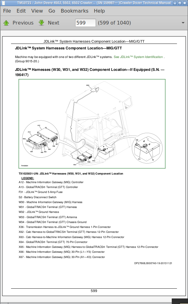
JDLink™ System Harnesses Component Location—MIG/GTT
JDLink™ System Harnesses Component Location—MTG/SAT
JDLink™ System Wiring Diagrams—MIG/GTT
JDLink™ Ground Harness (W32) Wiring Diagram—If Equipped
JDLink™ System Wiring Diagrams—MTG/SAT
Group 15: Sub-System Diagnostics
Starting and Charging Circuit Theory of Operation
Controller Area Network (CAN) Circuit Theory of Operation
Engine Control Unit (ECU) Circuit Theory of Operation
Standard Display Monitor (SDM) Circuit Theory of Operation
Transmission Control Unit (TCU) Circuit Theory of Operation
Integrated Grade Control (IGC) Circuit Theory of Operation—If Equipped
JDLink™ Circuit Theory of Operation—If Equipped
Group 16: Monitor Operation
Standard Display Monitor (SDM) Menu Structure—Service Mode
Standard Display Monitor (SDM)—Change Units
Standard Display Monitor (SDM)—Hide/Unhide Main Menu
Standard Display Monitor (SDM)—Setting Hour Meter
Group 20: References
Service ADVISOR™ Diagnostic Application
Service ADVISOR™ Connection Procedure
Reading Diagnostic Trouble Codes with Service ADVISOR™ Diagnostic Application
JDLink™ System Identification
JDLink™ Connection Procedure—If Equipped
Alternator Test
CAN Circuit Test
Electrical Component Specifications
Transmission Control Unit (TCU) Calibration
Integrated Grade Control (IGC) Checks—If Equipped
Integrated Grade Control (IGC) Diagnose Malfunctions—If Equipped
Decelerator/Brake Pedal Adjustment
Engine Speed Control Remove and Install
Rotary Sensor Remove and Install
Transmission Control Lever (TCL) Adjustment
Replace Weather Pack™ Connector
Install Weather Pack™ Contact
Replace DEUTSCH® Connectors
Replace Rectangular or Triangular Connectors
Install DEUTSCH® Contact
Repair 32 and 48 Way CINCH™ Connectors
Replace (Pull Type) Metri-Pack™ Connectors
Replace (Push Type) Metri-Pack™ Connectors
Section 9025: Hydraulic System
Group 05: Theory of Operation
Hydraulic System Operation
Hydraulic Pump Operation
Hydraulic Pump and Reservoir Operation
Hydraulic Filter Operation
Hydraulic Control Valve Operation
Hydraulic System Relief Valve Operation
Inlet Valve Operation
Auxiliary Valve Operation
Blade Lift Valve Operation
Blade Angle Valve Operation
Blade Tilt Valve Operation
Outlet Valve Cover Operation
Hydraulic Control Valve Operation—IGC
Hydraulic Cylinder Operation
Group 15: Diagnostic Information
Hydraulic System Schematic
Hydraulic System Schematic—IGC
Hydraulic Component Location
Hydraulic Component Location—IGC
Ripper Hydraulic Component Location
Hydraulic System Diagnose Malfunctions
Hydraulic System Diagnose Malfunctions—IGC
Group 20: Adjustments
Hydraulic Control Lever Linkage Adjustment
Auxiliary Lever Linkage Adjustment
Blade Pitch Linkage Adjustment
Group 25: Tests
Hydraulic Oil Warm-Up Procedure
Hydraulic Oil Sampling Procedure—If Equipped
Hydraulic Pump Flow Test
Hydraulic System Relief Valve Test
Hydraulic System Relief Valve Test—IGC
Circuit Relief Valve Test—With Remote Pump
Hydraulic Pump Cycle Time Test
Lift Cylinder Drift Test
Cylinder Leakage Test
Oil Clean-up Procedure
Section 9026: Hydrostatic System
Group 05: Theory of Operation
Hydrostatic System
Transmission Control Circuit Operation (Flow Chart)
Charge Pump Operation
Hydrostatic Filter Operation
Neutral Charge Relief Valve Operation
Park Brake Operation
Multi-Function Valve Operation
Oil Cooler Bypass Valve Operation
Pump Pressure Control Pilot (PCP) Operation
Pump Displacement Control Valve (PDCV) Operation
Hydrostatic Pump Operation
Flushing Valve and Operating Charge Relief Valve Operation
Hydrostatic Motor Operation
Group 15: Diagnostic Information
Hydrostatic Schematic—Neutral (Park Brake ON)
Hydrostatic System Component Location
Hydrostatic System Diagram—Park Brake On (Neutral)
Hydrostatic System Diagram—Forward (Slow Speed)
Hydrostatic System Diagram—Reverse (Fast Speed)
Overheating Malfunctions
High/Low Charge Pressure Malfunctions
Mistrack/Index Malfunctions
Machine Full Speed Malfunctions
Low Power Malfunctions
Track Malfunctions
TCU Calibration Malfunctions
Group 25: Test
JT05800 Digital Thermometer Installation
Digital Pressure And Temperature Analyzer Installation
Hydraulic Oil Cleanup Procedure
Ultra Clean® Hand Launcher
Transmission Oil Warmup Procedure
Hydrostatic Oil Sampling Procedure—If Equipped
Releasing Park Brake to Tow the Machine
Hydrostatic Pump and Motor Initial Start-Up Procedure
Hydrostatic Pump Flushing Procedure
Pressure Control Pilot (PCP) Manual Override Test
Pressure Control Pilot (PCP) Test
Pressure Control Pilot (PCP) Internal Adjustment
Multi-Function Relief Valve Test
Transmission Efficiency Test
Neutral Charge Relief and Operating Charge Relief Pressure Test
Pump Displacement Control Valve (PDCV) Neutral (Null) Adjustment
Pump Servo Pressure Test
Hydrostatic Motor Min./Max. Angle Servo Piston Pressure Test
Hydrostatic Motor Min. Angle Stop Adjustment
Charge Pump Flow Test
Cooler Bypass Valve Test
Section 9031: Heating and Air Conditioning
Group 05: Theory of Operation
Air Conditioning System Cycle Of Operation
Group 15: Diagnostic Information
Air Conditioning System Diagnose Malfunctions
Heater System Diagnose Malfunctions
Group 25: Test
Proper Refrigerant Handling
R134a Refrigerant Cautions
R134a Oil Charge Capacity
R134a Refrigerant Charge Capacity
Refrigerant Hoses And Tubing Inspection
Operating Pressure Diagnostic Chart
Air Conditioner High/Low Pressure (Binary) Switch Test
Freeze Control Switch Test
Leak Testing
John Deere Crawler Dozer 450J, 550J, 650J Operation & Test Service Manual (TM10721)
![]()