
John Deere 950C Crawler Dozer Repair Service Manual (TM2247)
John Deere 950C Crawler Dozer Repair Service Manual (TM2247)
TM2247 -John Deere 950C Crawler Dozer Technical Manual - Repair.PDF
Complete service repair manual for John Deere 950C Crawler Dozer, with all the shop information to maintain, repair, rebuild like professional mechanics.
John Deere 950C Crawler Dozer workshop service repair manual includes:
* Numbered table of contents easy to use so that you can find the information you need fast.
* Detailed sub-steps expand on repair procedure information
* Numbered instructions guide you through every repair procedure step by step.
* Notes, cautions and warnings throughout each chapter pinpoint critical information.
* Bold figure number help you quickly match illustrations with instructions.
* Detailed illustrations, drawings and photos guide you through every procedure.
* Enlarged inset helps you identify and examine parts in detail.
PRODUCT DETAILS:
Total Pages: 491 pages
File Format: PDF (bookmarked, ToC, Searchable, Printable, high quality)
Language: English
MAIN SECTIONS
Foreword
Technical Information Feedback Form
General Information
Safety
Torque Values
Tracks
Track System
Axles and Suspension Systems
Drive Axle Housing and Support
Axle Shaft, Bearings, and Reduction Gear
Transmission
Removal and Installation
Engine
Removal and Installation
Engine Auxiliary Systems
Cooling Systems
Speed Controls
Dampener Drive
Elements
Transfer or Splitter Drive
Removal and Installation
Park Brake
Removal and Installation
Hydraulic System
Frame or Supporting Structure
Frame Installation
Operator’s Station
Removal and Installation
Seat and Seat Belt
Heating and Air Conditioning
Sheet Metal and Styling
Grille and Grille Housing
Main Hydraulic System
Hydraulic System
Bulldozer
Blades
Frames
Hydraulic System
Ground Conditioning Tool
Hydraulic System
Dealer Fabricated Tools
tm2247 - 950c crawler dozer repair
Table of Contents
Foreword
Technical Information Feedback Form
Section 00: General Information
Group 0001: Safety
Recognize Safety Information
Follow Safety Instructions
Operate Only If Qualified
Wear Protective Equipment
Avoid Unauthorized Machine Modifications
Inspect Machine
Add Cab Guarding For Special Uses
Stay Clear Of Moving Parts
Avoid High-Pressure Fluids
Beware Of Exhaust Fumes
Prevent Fires
Prevent Battery Explosions
Handle Chemical Products Safely
Dispose of Waste Properly
Prepare for Emergencies
Start Only From Operator's Seat
Use And Maintain Seat Belt
Prevent Unintended Machine Movement
Avoid Work Site Hazards
Keep Riders Off Machine
Avoid Backover Accidents
Avoid Machine Tip Over
Park And Prepare For Service Safely
Service Cooling System Safely
Remove Paint Before Welding or Heating
Make Welding Repairs Safely
Drive Metal Pins Safely
Live With Safety
Group 0003: Torque Values
Metric Standard Thread Bolts and Cap Screws Torque Values
Metric Fine Thread Bolts and Cap Screws Torque Values
Metric Series Four-Bolt Flange Fittings For Standard Pressure, SAE Code 61, Service Recommendations
Metric Series Four Bolt Flange Fitting For High Pressure, SAE Code 62, Service Recommendations
Oil Drain Plugs For Final Drive Service Recommendations
ERMETO Type Screw Couplings Service Recommendations
WALTERSCHEID Type Couplings Service Recommendations
VOSS Type Couplings Service Recommendations
Section 01: Tracks
Group 0130: Track System
Front Idler Remove and Install
Track Adjuster and Recoil Spring Remove and Install
Track Adjuster and Recoil Spring Disassemble and Assemble
Track Frame Remove and Install
Track Frame Supports Remove and Install
Pivot Shaft Remove and Install
Crossbar Remove and Install
Crossbar Pivot Bearing Remove and Install
Section 02: Axles and Suspension Systems
Group 0201: Drive Axle Housing and Support
Final Drive Remove and Install
Group 0250: Axle Shaft, Bearings, and Reduction Gear
Final Drive Metal Face Seal Remove and Install
Metal Face Seal Inspection
Section 03: Transmission
Group 0300: Removal and Installation
Hydrostatic Motor Remove and Install
High Pressure Hoses Remove and Install
Section 04: Engine
Group 0400: Removal and Installation
Engine Remove and Install
Injection Pump Timing Check (Spill Port Method-Fuel Delivery Begin)
Injection Pump Timing Adjustment (Spill Port Method-Fuel Delivery Begin)
Section 05: Engine Auxiliary Systems
Group 0510: Cooling Systems
Fan and Shroud Remove and Install
Radiator Remove and Install
Group 0515: Speed Controls
Speed Control Linkage Remove and Install
Speed Control Lever Adjustment
Speed Control Lever Force Adjustment
Section 07: Dampener Drive
Group 0752: Elements
Dampener Drive Remove and Install
Section 08: Transfer or Splitter Drive
Group 0800: Removal and Installation
Splitter Drive Remove and Install
Section 11: Park Brake
Group 1100: Removal and Installation
Park Brake Remove and Install
Park Brake Bleed Procedure
Group 1160: Hydraulic System
Park Brake Disassemble and Assemble
Park Brake Solenoid Valve Remove and Install
Section 17: Frame or Supporting Structure
Group 1740: Frame Installation
Welding On Machine
Section 18: Operator’s Station
Group 1800: Removal and Installation
Cab Remove and Install
Group 1821: Seat and Seat Belt
Mechanical Suspension Seat Remove and Install
Mechanical Suspension Seat Disassemble and Assemble
Air Suspension Seat Remove and Install
Air Suspension Seat Disassemble and Assemble
Group 1830: Heating and Air Conditioning
Proper Refrigerant Handling
R134a Refrigerant Cautions
Air Conditioning Compressor Remove and Install
Section 19: Sheet Metal and Styling
Group 1921: Grille and Grille Housing
Grille Housing Remove and Install
Section 21: Main Hydraulic System
Group 2160: Hydraulic System
Hydraulic Fan Drive Pump Disassemble and Assemble
Hydraulic Fan Drive Pump Control Valve Disassemble and Assemble
Hydraulic Fan Drive Motor Disassemble and Assemble
Section 32: Bulldozer
Group 3201: Blades
Angle Blade Remove and Install
Straight and Semi-U Blade Remove and Install
Group 3240: Frames
Angle Blade Dozer Frame Remove and Install
Straight and Semi-U Blade Dozer Frame Remove and Install
Group 3260: Hydraulic System
Dozer Control Valve Disassemble and Assemble
Tilt Cylinder-Angle Blade Disassemble and Assemble
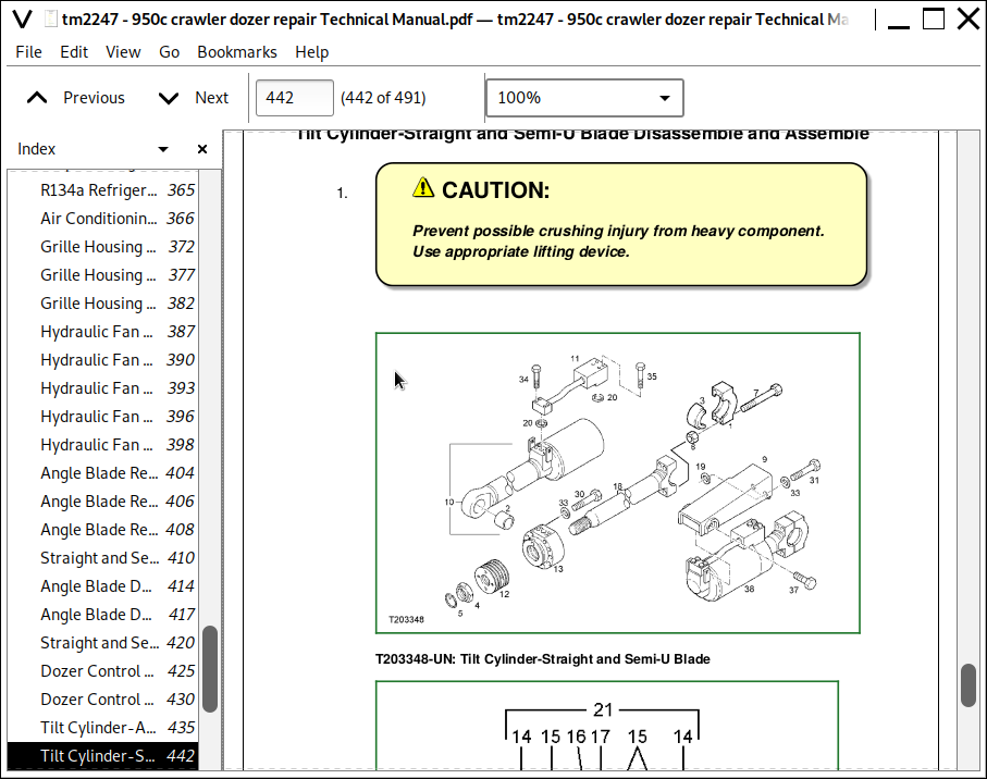
Tilt Cylinder-Straight and Semi-U Blade Disassemble and Assemble
Pitch Cylinder-Straight Blade Disassemble and Assemble
Pitch Cylinder-Semi-U Blade Disassemble and Assemble
Blade Lift Cylinder Disassemble and Assemble
Section 42: Ground Conditioning Tool
Group 4260: Hydraulic System
Auxiliary Control Valve Disassemble and Assemble
Ripper Lift Cylinder Disassemble and Assemble
Section 99: Dealer Fabricated Tools
Group 9900: Dealer Fabricated Tools
DFT1119 Pump Support
DFT1251 Socket Wrench
DFT1250 Lifting Bracket
![]()