
John Deere 950J Crawler Dozer Repair Service Manual (TM2364)
Complete service repair manual for John Deere 950J Crawler Dozer, with all the service information to maintain, repair, and rebuild like professional mechanics.
John Deere 950J Crawler Dozer workshop service repair manual includes:
* Numbered table of contents easy to use so that you can find the information you need fast.
* Detailed sub-steps expand on repair procedure information
* Numbered instructions guide you through every repair procedure step by step.
* Notes, cautions and warnings throughout each chapter pinpoint critical information.
* Bold figure number help you quickly match illustrations with instructions.
* Detailed illustrations, drawings and photos guide you through every procedure.
* Enlarged inset helps you identify and examine parts in detail.
TM2364 -John Deere 950J Crawler Dozer Technical Manual - Repair.PDF
TM2364 -John Deere 950J Crawler Dozer Technical Manual - Repair.epub
Total Pages: 92 pages
File Format: PDF/EPUB/MOBI/AZW (PC/Mac/Android/Kindle/iPhone/iPad; bookmarked, ToC, Searchable, Printable)
Language: English
MAIN SECTIONS
Foreword
Technical Information Feedback Form
General Information
Safety
Torque Values
Tracks
Track System
Axles and Suspension Systems
Drive Axle Housing and Support
Axle Shaft, Bearings, and Reduction Gear
Transmission
Removal and Installation
Control Linkage
Hydraulic System
Engine
Removal and Installation
Exhaust Manifold
Engine Auxiliary Systems
Cold Weather Starting Aid
Cooling Systems
Speed Controls
Intake System
External Exhaust Systems
External Fuel Supply Systems
Dampener Drive
Elements
Transfer or Splitter Drive
Removal and Installation
Gears, Shafts, and Bearings
Park Brake
Removal and Installation
Control Linkage
Hydraulic System
Equipment Attaching
Drawbar
Frame or Supporting Structure
Frame Installation
Frame Bottom Guards
Chassis Weights
Operator’s Station
Removal and Installation
Operator Enclosure
Seat and Seat Belt
Heating and Air Conditioning
Sheet Metal and Styling
Hood and Engine Enclosure
Grille and Grille Housing
Main Hydraulic System
Hydraulic System
Bulldozer
Blades
Frames
Hydraulic System
Ground Conditioning Tool
Remove and Install
Blades, Teeth, and Shanks
Frames
Hydraulic System
Dealer Fabricated Tools
tm2364 - 950J Crawler Dozer
Table of Contents
Foreword
Technical Information Feedback Form
Section 00: General Information
Group 01: Safety
Recognize Safety Information
Follow Safety Instructions
Operate Only If Qualified
Wear Protective Equipment
Avoid Unauthorized Machine Modifications
Inspect Machine
Stay Clear of Moving Parts
Avoid High-Pressure Fluids
Beware of Exhaust Fumes
Prevent Fires
Prevent Battery Explosions
Handle Chemical Products Safely
Dispose of Waste Properly
Prepare for Emergencies
Use Steps and Handholds Correctly
Add Cab Guarding For Special Uses
Start Only From Operator's Seat
Use and Maintain Seat Belt
Prevent Unintended Machine Movement
Avoid Work Site Hazards
Add and Operate Attachments Safely
Keep Riders Off Machine
Avoid Backover Accidents
Avoid Machine Tip Over
Park And Prepare For Service Safely
Service Cooling System Safely
Remove Paint Before Welding or Heating
Make Welding Repairs Safely
Drive Metal Pins Safely
Live With Safety
Group 0003: Torque Values
Metric Standard Thread Bolts and Cap Screws Torque Values
Metric Fine Thread Bolts and Cap Screws Torque Values
Metric Series Four-Bolt Flange Fittings For Standard Pressure, SAE Code 61, Service Recommendations
Metric Series Four Bolt Flange Fitting For High Pressure, SAE Code 62, Service Recommendations
Oil Drain Plugs For Final Drive Service Recommendations
ERMETO Type Screw Couplings Service Recommendations
WALTERSCHEID Type Couplings Service Recommendations
VOSS Type Couplings Service Recommendations
Section 01: Tracks
Group 0130: Track System
Rock Guards and Chain Guide Remove and Install
Carrier Roller Wear Inspection
Carrier Roller Remove and Install
Carrier Roller Disassemble and Assemble (S.N. —009309)
Carrier Roller Disassemble and Assemble (S.N. 009310— )
Metal Face Seal Inspection
Carrier Roller Leakage Test
Track Roller Wear Inspection
Track Roller Remove and Install
Track Roller Disassemble and Assemble
Track Roller Leakage Test
Track Grouser Wear Inspection
Track Shoe Remove and Install
Track Link Height Inspection
Track Bushing Outer Diameter Inspection
Track Pitch Inspection
Check and Adjust Track Sag
Track Remove and Install
Track Frame Remove and Install
Pivot Shaft Remove and Install
Crossbar Remove and Install
Crossbar Pivot Bearings Remove and Install
Track Frame Wear Strips Remove and Install
Front Idler Wear Inspection
Front Idler Remove and Install
Front Idler Disassemble and Assemble
Front Idler Leakage Test
Front Idler Adjustment
Track Adjuster Remove and Install
Track Adjuster Disassemble and Assemble
Recoil Spring Remove and Install
Sprocket Wear Inspection
Sprocket Segment Remove and Install
Section 02: Axles and Suspension Systems
Group 0201: Drive Axle Housing and Support
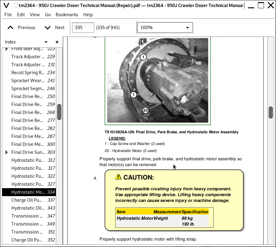
Final Drive Remove and Install
Group 0250: Axle Shaft, Bearings, and Reduction Gear
Final Drive Bearing Adjustment
Final Drive Metal Face Seal Remove and Install
Final Drive Metal Face Seal Inspection
Final Drive Sun Gear Remove and Install (950J S.N. 9104— and 1050J S.N. 10004— )
Section 03: Transmission
Group 0300: Removal and Installation
Hydrostatic Pump and Motor Initial Start-up Procedure
Hydrostatic Pump Remove and Install
Hydrostatic Motor Remove and Install
Charge Oil Pump Remove and Install
Hydrostatic Oil Cooler Remove and Install
Group 0315: Control Linkage
Transmission Control Lever (TCL) Remove and Install
Transmission Control Lever (TCL) Disassemble and Assemble
Group 0360: Hydraulic System
Charge Oil Pump Disassemble and Assemble
Hydrostatic Pump Displacement Control Disassemble and Assemble
Section 04: Engine
Group 0400: Removal and Installation
Engine Remove and Install
Engine Oil Cooler Remove and Install
Flywheel Remove and Install
Crankshaft Front Pulley Remove and Install
Crankshaft Main Bearings Remove and Install
Camshaft Gears Remove and Install
Engine Front Cover Remove and Install
Engine Oil Pan Remove and Install
Fuel Injector Remove and Install
Fuel Injection Pump Remove and Install
Engine Control Unit (ECU) Remove and Install
Group 0410: Exhaust Manifold
Exhaust Manifold Remove and Install
Section 05: Engine Auxiliary Systems
Group 0505: Cold Weather Starting Aid
Engine Coolant Heater Remove and Install
Starting Aid Remove and Install
Group 0510: Cooling Systems
Fan Shroud Remove and Install
Fan Blade Remove and Install
Coolant Pump Remove and Install
Serpentine Belt Tensioner Remove and Install
Engine Cooling Package Remove and Install
Engine Cooling Package Disassemble and Assemble
Fuel Cooler Remove and Install
Group 0515: Speed Controls
Engine Speed Control Remove and Install
Decelerator / Brake Pedal Remove and Install
Decelerator / Brake Pedal Disassemble and Assemble
Group 0520: Intake System
Air Cleaner Remove and Install
Group 0530: External Exhaust Systems
Muffler Remove and Install
Group 0560: External Fuel Supply Systems
Fuel Tank Remove and Install
Section 07: Dampener Drive
Group 0752: Elements
Dampener Drive Remove and Install
Section 08: Transfer or Splitter Drive
Group 0800: Removal and Installation
Splitter Drive Remove and Install
Group 0851: Gears, Shafts, and Bearings
Splitter Drive Disassemble and Assemble
Section 11: Park Brake
Group 1100: Removal and Installation
Park Brake Remove and Install
Group 1115: Control Linkage
Park Lock Lever Remove and Install
Group 1160: Hydraulic System
Park Brake Solenoid Valve Remove and Install
Section 15: Equipment Attaching
Group 1511: Drawbar
Drawbar Remove and Install
Section 17: Frame or Supporting Structure
Group 1740: Frame Installation
Welding Repair of Major Structures
Group 1746: Frame Bottom Guards
Bottom Guards Remove and Install
Group 1749: Chassis Weights
Rear Counterweight Remove and Install
Section 18: Operator’s Station
Group 1800: Removal and Installation
Cab / ROPS Remove and Install
Cab Isolators Remove and Install
Group 1810: Operator Enclosure
Windowpane, Sliding Window, and Two-Piece Moulding Remove and Install
Sliding Window Disassemble and Assemble
Window Wipers Remove and Install
Window Washer Pumps Remove and Install
Group 1821: Seat and Seat Belt
Air Suspension Seat Remove and Install
Air Suspension Seat Disassemble and Assemble
Group 1830: Heating and Air Conditioning
Proper Refrigerant Handling
R134a Refrigerant—Cautions
R134a Compressor Oil Charge Check
R134a Compressor Oil Removal
R134a Component Oil Charge
R134a Refrigerant Recovery/Recycling and Charging Station Installation Procedure
Recover R134a Refrigerant
Evacuate R134a System
Charge R134a System
Leakage Testing
Flush and Purge Air Conditioner System
Compressor Remove and Install
Condenser Remove and Install
High/Low Pressure Switch Remove and Install
Receiver-Dryer Remove and Install
Expansion Valve Remove and Install
Evaporator Core Remove and Install
Cab Heater/Air-Conditioning Unit Disassemble and Assemble
Cab Blower Motor and Blower Motor Resistor Remove and Install
Expansion Valve Temperature Sensor Remove and Install
Evaporator Temperature Sensor Remove and Install
Heater Core Remove and Install
Heater Valve Remove and Install
Section 19: Sheet Metal and Styling
Group 1910: Hood and Engine Enclosure
Hood Remove and Install
Hood Support Remove and Install
Engine Side Shields Remove and Install
Group 1921: Grille and Grille Housing
Grille Remove and Install
Section 21: Main Hydraulic System
Group 2160: Hydraulic System
General Oil Cleanup Procedure
Hydraulic/Hydrostatic Component Failure Cleanup Procedure
Case Drain Filter Inspection
Hydraulic Pump Remove and Install
Hydraulic Pump Disassemble and Assemble
Hydraulic Pump Regulator Assembly Remove and Install
Hydraulic Fan Drive Pump Remove and Install
Hydraulic Fan Drive Pump Disassemble and Assemble
Hydraulic Fan Drive Pump Regulator Assembly Remove and Install
Radiator and Charge Air Cooler Fan Drive Motor Remove and Install
Radiator and Charge Air Cooler Fan Drive Motor Disassemble and Assemble
Hydrostatic Oil Cooler Fan Drive Motor Remove and Install
Hydraulic Oil Reservoir Remove and Install
Section 32: Bulldozer
Group 3201: Blades
Dozer Blade Remove and Install
Cutting Edges and End Bits Remove and Install
Group 3240: Frames
Pushbeam Remove and Install
Group 3260: Hydraulic System
Main Control Valve Remove and Install
Main Control Valve Disassemble and Assemble
System Relief Valve Remove and Install
Blade Lower Circuit Relief Valve Remove and Install
Quick-Drop Return Shutoff Solenoid Valve
Pilot Control Valve Remove and Install
Pilot Control Valve Lever Disassemble and Assemble
Quick-Drop Valve Assembly Remove and Install
Quick-Drop Valve Assembly Disassemble and Assemble
Tilt Cylinder Remove and Install
Tilt Cylinder Disassemble and Assemble
Blade Lift Cylinder Remove and Install
Blade Lift Cylinder Yoke Remove and Install
Blade Lift Cylinder Disassemble and Assemble
Section 42: Ground Conditioning Tool
Group 4200: Remove and Install
Ripper Remove and Install
Group 4201: Blades, Teeth, and Shanks
Shank and Tooth Remove and Install
Group 4240: Frames
Ripper Frame Disassemble and Assemble
Group 4260: Hydraulic System
Auxiliary Control Valve Disassemble and Assemble
Auxiliary Pilot Control Valve Remove and Install
Ripper Lift Cylinder Remove and Install
Ripper Pitch Cylinder Remove and Install
Ripper Cylinder Disassemble and Assemble
Section 99: Dealer Fabricated Tools
Group 9900: Dealer Fabricated Tools
DF1063 Lift Bracket
DF1065 Adapter Bracket
DFT1276 21 mm Wrench with 1/2 in. Drive
DFT1277 24 mm Wrench with 1/2 in. Drive
DFT1278 30 mm Wrench with 3/4 in. Drive
DFT1280 Final Drive Bearing Puller and Installer
DFT1299 Rolling Drag Bar
JT38076 Crossbar End Bearing Driver
John Deere 950J Crawler Dozer Repair Service Manual (TM2364)
![]()