
John Deere 280, 284, 300, 304, 320, 324 Tractors Service Manual
Complete All Inclusive Technical Manual with electrical wiring diagrams for John Deere 280, 284, 300, 304, 320, 324 Tractors, with workshop information to maintain, diagnose, repair, and rebuild like professional mechanics (Diagnosis, Operation, Tests, Repair, Service, Troubleshooting).
John Deere 280, 284, 300, 304, 320, 324 Tractors workshop technical service manual includes:
* Numbered table of contents easy to use so that you can find the information you need fast.
* Detailed sub-steps expand on repair procedure information
* Numbered instructions guide you through every repair procedure step by step.
* Troubleshooting and electrical service procedures are combined with detailed wiring diagrams for ease of use.
* Notes, cautions and warnings throughout each chapter pinpoint critical information.
* Bold figure number help you quickly match illustrations with instructions.
* Detailed illustrations, drawings and photos guide you through every procedure.
* Enlarged inset helps you identify and examine parts in detail.
TM700419 - John Deere 280,284,300,304,320,324 Tractors Service Manual.PDF
PRODUCT DETAILS:
Total Pages: 858 pages
File Format: PDF/EPUB/MOBI/AZW (PC/Mac/Android/Kindle/iPhone/iPad; bookmarked, ToC, Searchable, Printable)
Language: English
MAIN SECTIONS
Foreword
General information
Safety regulations
Technical specifications
Fuel and lubricant oil
Position of serial number plate
Discharge oil and water before servicing
Engine
Engine
Cooling system
Fuel system, air intake and exhaust
Speed control lever
Fuel system
Air intake and exhaust system
Electrical system
Battery and engine
Electrical system components
Wiring harness
Fuses and relays
Electrical schematic
Drive system
Rear PTO shaft
Clutch
Feeder
Gearbox
Rear differential
Final drive
MFWD
Steering and brake
Steering system
Brake
Air brake (optional)
Hydraulic system
Hydraulic pump and lifter filter element
Lifter
Hydraulic oil pipe
Trailer device
Miscellaneous
Engine hood and shield
Three-point suspension device
Wheel
Front counterweight tray
Driving cab
Remove and install components
Seat
Special tools (made by dealers)
Special tools (made by dealers)
Work checking procedures
Work checking procedures
Engine operational principles, test and adjust
Component locations
Operational principles
Diagnose, test and adjust
Operational principles, test and adjustment of fuel/air intake system
Component locations
Operational principles
Diagnose, test and adjust
Operational principles, test and adjustment of electrical system
Component locations
Operational principles
Diagnose, test and adjust
Circuit diagram
Operational principles, test and adjustment of drive system
Component locations
Operational principles
Diagnose, test and adjust
Operational principles, test and adjustment of steering and braking devices
Component locations
Operational principles
Diagnose, test and adjust
Operational principles, test and adjustment of hydraulic system
Component locations
Operational principles
Diagnose, test and adjust
TABLE OF CONTENTS................1
Section 10: General information................195
Group 05: Safety regulations................18
Live With Safety................23
Recognize Safety Information................24
Understand the meaning of sign words................25
Follow Safety Instructions................26
Handle Fluids Safely—Avoid Fires................27
Prevent Battery Explosions................28
Handle Batteries Safely................29
Prepare for Emergencies................30
Remove Paint Before Welding or Heating................31
Avoid High-Pressure Fluids................32
Engine Coolant................33
Prevent Machine Runaway................34
Avoid Heating Near Pressurized Fluid Lines................35
Work In Ventilated Area................36
Use starting fluid safely................37
Wear Protective Clothing................38
Noise isolation................39
Service front-wheel driven tractor safely................40
Tighten wheels-fixing bolts/nuts................41
Store implements safely................42
Produce dealer self-made tools safely................43
Use fuel safely - prevent fire................44
Practice Safe Maintenance................45
Stay away from rotating drive shaft................46
Use steps and handrails correctly................47
Operate tractor safely................48
Limited use for forestry operation................51
Use loader and tractor safely................52
Keep riders off the machine................53
Instructor's seat................54
Using safety warning lights and devices................55
Use safety chains................56
Transport towed implements at safe speed................57
Be cautious on slopes and uneven terrain................59
Drag a machine out of mud pits................60
Avoid contact with pesticides................61
Handle pesticides safely................62
Handle Global Positioning System (GPS) receiver safely................64
Stay away from high-temperature radiation................65
Avoid tractor being out of control................66
Transport tractor safely................67
Service the cooling system safely................68
Service the accumulator system safely................69
Park Machine Safely................70
Use Proper Lifting Equipment................71
Support Machine Safely................72
Work in Clean Area................73
Illuminate Work Area Safely................74
Service Machines Safely................75
Use Proper Tools................76
Service Tires Safely................77
Safe Servicing of Front-Wheel Drive................78
Use Seat Belt Properly................79
Keep ROPS Installed Properly................80
Dispose of Waste Properly................81
Group 10: Technical specifications................628
Technical specifications of 2WD machine................87
MFWD technical specifications................92
Front-wheel drive axle oil (standard)................98
Maximum control force................99
Minimum turning radius................100
PTO shaft properties................101
Traction properties................102
Properties of hydraulic suspension system................103
Pouring capacity (L)................104
Metric bolt and screw torque values................105
Torque values of imperial bolts and screws................107
Hydraulic system imperial connector torque................110
Hydraulic system metric connector torque................111
Clean air filter................113
Check hose clamps................114
Clear the dust on engine cover and hood grille................115
Clean radiator................116
Check the oil level of gearbox and lifter................117
Clean battery................118
Check neutral start circuit................119
Tractor operation check................120
Group 15: Fuel and lubricant oil................20
Handle fuel safely — Avoid fire................122
Handle fluid safely — Avoid fire................123
Handling and storing of diesel fuel................124
Cold weather operation................125
Hot weather operation................126
Diesel................127
Lubricity of diesel................129
Test diesel................130
Fill the fuel tank................131
Alternative and synthetic lubricant oil................133
Storage of lubricant oil................134
Diesel engine break-in oil................135
Diesel engine oil................137
Engine oil filter................139
Heavy-duty diesel engine coolant................140
Liquid coolant conditioner................142
Transmission and hydraulic oil................143
Refuel gearbox................144
Regularly check and service the gearbox................145
Use correct transmission/hydraulic oil filter elements................146
Lubricating grease (specific applications)................147
Lubricating grease................148
Group 20: Position of serial number plate................21
Serial number................150
Tractor serial number................151
Tractor machine serial number - 13 digits PIN................152
Engine serial number................153
Group 25: Discharge oil and water before servicing................21
MFWD model front axle oil discharge................155
MFWD model drive transfer case oil discharge................156
Steering oil tank discharge................157
Gearbox oil discharge................158
Lifter oil discharge................159
Oil tank diesel discharge................160
Discharge cooling water................161
Engine oil discharge................163
Section 20: Engine................164
Group 05: Engine................164
Basic or recommended tools................166
Technical specifications................628
Engine maintenance................168
Remove and install engine................219
Group 10: Cooling system................164
Technical specifications................628
Maintenance of engine water pump................175
Remove, install and adjust fan drive belt................176
Remove, check and install radiator................178
Remove thermostat................182
Install thermostat................184
Section 30: Fuel system, air intake and exhaust................186
Group 05: Speed control lever................186
Technical specifications................628
Check and repair engine control mechanism assembly................189
Adjust throttle lever................191
Adjust synchronization of foot throttle pedal and throttle handle................192
Group 10: Fuel system................186
General information................195
Technical information................196
Remove, check and install fuel tank................197
Replace fuel transfer pump................200
Replace sediment bowl................201
Replace fuel filter................203
Exhaust air from fuel system................635
Group 15: Air intake and exhaust system................186
Technical specifications................628
Remove, check and install air filter................209
Remove, check and install muffler................211
Section 40: Electrical system................213
Group 05: Battery and engine................213
Remove and install battery................217
Remove and install engine................219
Group 10: Electrical system components................213
Service equipment and tools................222
Replace water temperature sensor................223
Replace engine oil pressure sensor................224
Replace dashboard................225
Replace keyswitch................227
Replacement light switch / working light switch / warning light switch................230
Replace high/low beam switch / turning signal switch / horn switch................232
Replace brake light switch................234
Replace gearbox neutral switch................236
Replace PTO shaft neutral switch................238
Replace horn................239
Replace flasher................240
Replace trailer socket (optional)................241
Replace air pressure alarm switch (optional)................242
Group 15: Wiring harness................662
Cable repair pliers................244
Remove and install electrical connectors................245
Separate blade terminals and connectors................246
Replace connector................247
Install contact................249
Replace tractor wiring harness................250
Battery cables, headlight wiring harness, engine wiring harness................251
Left rear light wiring harness, right rear light wiring harness, start relay wiring harness, meter and switch wiring harness................252
Group 20: Fuses and relays................213
Locations of fuses................254
Fuse specifications and functions................255
Replace start relay................256
Group 25: Electrical schematic................749
Cable color codes................748
Electrical schematic................749
Section 50: Drive system................261
Group 10: Rear PTO shaft................261
Exploded view of rear PTO control assembly................265
Exploded view of PTO shaft protection cover assembly................267
Exploded view of PTO shaft................268
Remove, check and assemble PTO control assembly................270
Remove and check rear PTO shaft assembly................273
Assemble rear PTO shaft assembly................278
Group 15: Clutch................261
Exploded view of clutch assembly (single)................287
Exploded view of clutch assembly (double)................288
Disassemble, check and assemble clutch assembly (single)................290
Group 20: Feeder................261
Exploded view of feeder (single clutch)................297
Exploded view of feeder (dual clutch)................299
Remove and install feeder................302
Disassemble, check and assemble feeder................304
Group 25: Gearbox................261
Exploded view of gearbox................308
Exploded view of gearbox (MFWD)................310
Exploded view of first shaft................312
Exploded view of first shaft (dual clutch)................314
Exploded view of second shaft................316
Exploded view of second shaft (dual clutch)................318
Exploded view of gearbox cover................319
Remove and install gearbox................321
Remove and install gearbox cover................325
Disassemble, check and assemble shift shaft................327
Disassemble and check first shaft and second shaft................329
Assemble first shaft and second shaft................334
Group 30: Rear differential................261
General repair procedures - rear differential................347
Exploded view of differential assembly................348
Remove and install differential assembly................349
Disassemble, check and assemble differential assembly................353
Adjust differential backlash................358
Group 35: Final drive................262
General repair procedures - final drive................360
Exploded view of final drive assembly................361
Remove and install final drive assembly................363
Disassemble and check final drive assembly................367
Assemble final drive assembly................370
Group 40: MFWD................262
Exploded view of MFWD control handle................375
Exploded view of drive transfer case and drive shaft................376
Remove and install drive transfer case................378
Disassemble, check and assemble drive transfer case................381
Exploded view of front box................387
Disassemble and check front box................390
Assemble front box................396
Exploded view of front wheel final drive assembly................406
Disassemble and check front wheel final drive assembly................408
Assemble front wheel final drive assembly................415
Section 60: Steering and brake................427
Group 05: Steering system................427
Technical specifications................628
Remove and install steering wheel................430
Remove and install steering column (MFWD)................431
Remove and install steering column (2WD)................432
Remove and check steering gear aggregate (2WD)................436
Disassemble hydraulic steering oil tank (MFWD)................440
Remove, check and install steering cylinder assembly (MFWD)................442
Disassemble constant flow pump................446
Disassemble full hydraulic steering gear................448
Adjust toe-in (MFWD)................833
Adjust front wheel toe-in and wheel tread (2WD model)................455
Group 10: Brake................427
Technical specifications................628
Disassemble and check brake pedal and connection lever mechanism................461
Disassemble and check brake drum housing assembly................466
Install brake drum housing assembly................470
Install brake pedal and connection lever mechanism................475
Group 10B: Air brake (optional)................427
Remove and install brake valve................483
Remove and install air reservoir................485
Remove and install air outlet pipe connector................486
Remove and install bracket................487
Remove and install air pipe................488
Air pump maintenance................494
Section 70: Hydraulic system................495
Group 05: Hydraulic pump and lifter filter element................495
Remove and install gear pump................497
Remove and install lifter filter element................498
Group 10: Lifter................495
Technical specifications................628
Remove and install lifter assembly................501
Group 15: Hydraulic oil pipe................495
Technical specifications................628
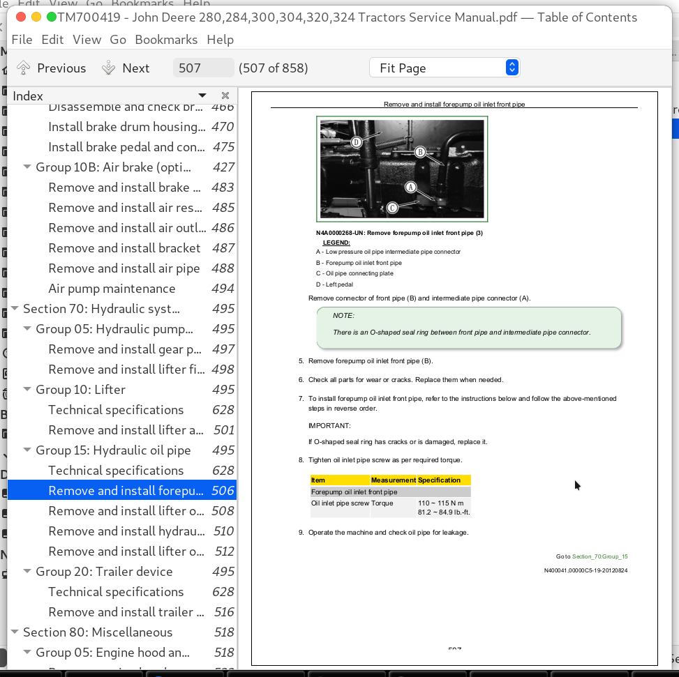
Remove and install forepump oil inlet front pipe................506
Remove and install lifter oil pump inlet pipe................508
Remove and install hydraulic lifter oil pump outlet pipe................510
Remove and install lifter oil inlet pipe................512
Group 20: Trailer device................495
Technical specifications................628
Remove and install trailer device................516
Section 80: Miscellaneous................518
Group 05: Engine hood and shield................518
Remove engine hood................522
Install engine hood................525
Remove and install engine hood strut................527
Remove and install engine hood lock................528
Remove and install PTO shaft shield................530
Group 10: Three-point suspension device................518
Adjust upper lever................533
Remove and install upper lever assembly................534
Adjust oblique lever................536
Remove and install oblique lever................537
Remove and install lower lever................540
Adjust external stopper chain assembly................542
Remove and install external stopper chain................543
Group 15: Wheel................518
Technical specifications................628
Remove and install guide wheels................549
Remove and install front drive wheels................550
Remove and install drive wheels................551
Remove and install rear wheel counterweight................552
Group 20: Front counterweight tray................518
Remove, check and install front counterweight tray................556
Section 90: Driving cab................559
Group 05: Remove and install components................559
Remove and install fenders................564
Remove and install pedals................568
Remove and install rear-view mirrors................570
Remove and install toolbox................571
Group 10: Seat................559
Remove and install seat................575
Section 99: Special tools (made by dealers)................578
Group 05: Special tools (made by dealers)................578
Special tool Q23-5 for installing bearing 305................580
Special tool Q23-6 for installing bushes................581
Special tool Q22-56 for installing oil seals................582
Special tool Q22-57 for installing bearings................583
Special tool Q22-105 for installing brake camshaft................584
Special tool Q22-3 for installing reverse gear composite bush................585
Special tool Q23-3 for installing bearing 6207................586
Special tool Q22-106 for installing bearing 30211 inner ring................587
Section 210: Work checking procedures................588
Group 10: Work checking procedures................588
Information of work checking procedures................590
Engine oil level and status check................591
Coolant level and status check................593
Gearbox oil level check................595
Hydraulic oil check................597
Fan and belt check................599
Fuel system check................601
Air intake system check................603
Electrical system check................605
Hydraulic system check................606
Indicator bulb check................607
Engine start check................609
Steering check................610
Clutch check................611
Shift lever check................612
Brake check................614
Other checks................616
Section 220: Engine operational principles, test and adjust................617
Group 05: Component locations................617
Information of component locations................839
Engine external components - left side................620
Engine external components - right side................621
Group 10: Operational principles................617
Information of operational principles................843
Operational principles of engine cooling system................624
Group 15: Diagnose, test and adjust................617
Technical specifications................628
Cooling system test................629
Throttle adjustment................630
Fan/generator drive belt adjustment................633
Exhaust air from fuel system................635
Air filter blockage................637
Section 230: Operational principles, test and adjustment of fuel/air intake system................639
Group 05: Component locations................639
Information of component locations................839
Fuel system components................642
Air intake system components................643
Group 10: Operational principles................639
Information of operational principles................843
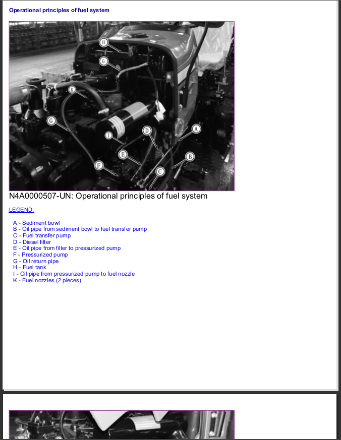
Operational principles of fuel system................647
Operational principles of air intake system................650
Group 15: Diagnose, test and adjust................639
Diagnostic information................848
Fuel/air intake system diagnosis, test and adjustment................653
Section 240: Operational principles, test and adjustment of electrical system................654
Group 05: Component locations................654
Information of component locations................839
Engine electrical components - right side................658
Engine electrical components - left side................659
Electrical components of dashboard and main control panel................660
Wiring harness................662
Group 10: Operational principles................654
Information of operational principles................843
Fuses................666
Relays................668
Operational principles of starting system................669
Operational principles of battery charging system................671
Operational principles of lighting system - left/right turning signal................673
Operational principles of lighting system - high/low beam and dashboard light................675
Operational principles of lighting system - working light................677
Operational principles of lighting system - taillight, front screen light and brake light................679
Operational principles of lighting system - hazard warning light................681
Operational principles of dashboard system - water temperature gauge................683
Operational principles of dashboard system - engine oil pressure indicator................685
Operational principles of air pressure indicator (optional)................687
Operational principles of horn................689
Group 15: Diagnose, test and adjust................654
Diagnostic information................848
Cable color table................695
Starting system test point - normal operation................696
Battery charging system test point................699
Lighting system test points - left/right turning signal................701
Lighting system test points - high/low beam and dashboard light................705
Lighting system test points - working light................709
Lighting system test points - taillight, front screen light and brake light................712
Lighting system test points - hazard warning light................716
Dashboard system test points - water temperature gauge................719
Dashboard system test points - engine oil pressure................722
Air pressure test point................725
Horn test point................727
Battery voltage test................729
Charging battery................730
Keyswitch test................731
Fuse test................733
Neutral start switch test................734
Light switch test................735
Turning signal switch test................737
Hazard alarm switch test................739
Working light switch test................741
Front floodlight high/low beam switch test................743
Horn switch test................745
Group 20: Circuit diagram................655
Cable color codes................748
Electrical schematic................749
Section 250: Operational principles, test and adjustment of drive system................750
Group 05: Component locations................750
Information of component locations................839
Drive system components................754
Clutch components................755
Gearbox components................758
Final drive components................760
Rear PTO components................762
Group 10: Operational principles................750
Information of operational principles................843
Operational principles of single-acting clutch................766
Operational principles of double-acting clutch................768
Operational principles of single-acting gearbox................770
Operational principles of double-acting gearbox................773
Operational principles of final drive................776
Operational principles of rear PTO shaft................778
Operational principles of drive transfer case transmission................780
Operational principles of MFWD................782
Group 15: Diagnose, test and adjust................750
Diagnostic information................848
Isolate defective components................787
Clutch slippage................789
Clutch incomplete separation................790
Clutch engagement................791
Clutch non-separation................792
Clutch pedal non-return................793
Unstable or unsteady power transmission................794
Gearbox oil level low (serious oil leakage)................795
Bumping gear, difficult shifting or non-engagement................796
Gearbox failing to stay at gear position................797
PTO shaft noisy................798
Difficulty in PTO shaft engagement................799
PTO shaft failing to stay at engaged status................800
Differential being noisy................801
Section 260: Operational principles, test and adjustment of steering and braking devices................802
Group 05: Component locations................802
Information of component locations................839
Steering system components................805
Shoe type braking system components................810
Group 10: Operational principles................802
Information of operational principles................843
Operational principles of mechanical steering system................813
Operational principles of hydraulic steering system................816
Operational principles of braking system................819
Group 15: Diagnose, test and adjust................802
Diagnostic information................848
Isolate defective components - steering system................824
Being difficult or failed to steer................825
Isolate defective components - brake................826
Steering cylinder leakage test................827
Check toe-in (2WD)................828
Adjust toe-in (2WD)................829
Check toe-in (MFWD)................832
Adjust toe-in (MFWD)................833
Brake pedal adjustment................835
Section 270: Operational principles, test and adjustment of hydraulic system................837
Group 05: Component locations................837
Information of component locations................839
Lifter assembly................840
Group 10: Operational principles................837
Information of operational principles................843
Operational principles of hydraulic system................844
Group 15: Diagnose, test and adjust................837
Diagnostic information................848
Preliminary checks of hydraulic system................849
Entire hydraulic system is not working / hydraulic oil pump does not supply oil................850
Insufficient oil supply from oil pump................851
Oil pump pressure is too high................852
Too much noise is generated when oil pump works................853
Lifter does not lift or lifting speed is too slow................854
John Deere 280, 284, 300, 304, 320, 324 Tractors Service Manual (TM700419)
![]()