
John Deere 1050C Crawler Dozer Operation & Test Service Manual (TM2300)

Complete Operation & Test manual with Electrical Wiring Diagrams for John Deere 1050C Crawler Dozer, with all the shop information to maintain, diagnose, and repair like professional mechanics.
John Deere 1050C Crawler Dozer workshop Operation & Test manual includes:
* Numbered table of contents easy to use so that you can find the information you need fast.
* Detailed sub-steps expand on repair procedure information
* Numbered instructions guide you through every repair procedure step by step.
* Troubleshooting and electrical service procedures are combined with detailed wiring diagrams for ease of use.
* Notes, cautions and warnings throughout each chapter pinpoint critical information.
* Bold figure number help you quickly match illustrations with instructions.
* Detailed illustrations, drawings and photos guide you through every procedure.
* Enlarged inset helps you identify and examine parts in detail.
TM2300 - John Deere 1050C Crawler Dozer Technical Manual - Operation and Test.PDF
TM2300 - John Deere 1050C Crawler Dozer Technical Manual - Operation and Test.epub
PRODUCT DETAILS:
Total Pages: 701 pages
File Format: PDF (bookmarked, ToC, Searchable, Printable, high quality)
Language: English
MAIN SECTIONS
Foreword
General Information
Safety
Operational Checkout Procedure
Operational Checkout Procedure
Engine
Theory of Operation
Diagnostic Information
Adjustments
Tests
Electrical System
System Information
System Diagrams
Sub-System Diagnostics
JDG10470376 Diagnostic Test Box
References
Power Train
Theory of Operation
Diagnostic Information
Pneumatic System
Theory of Operation
Diagnostic Information
Hydraulic System
Theory of Operation
Diagnostic Information
Adjustments
Tests
Hydrostatic System
Theory of Operation
Diagnostic Information
Adjustments
Tests
Heating and Air Conditioning
Theory of Operation
Diagnostic Information
Tests
Dealer Fabricated Tools
TABLE OF CONTENTS...1
Section 9000: General Information...12
Group 01: Safety...12
Recognize Safety Information...14
Follow Safety Instructions...15
Operate Only If Qualified...16
Wear Protective Equipment...17
Avoid Unauthorized Machine Modifications...18
Inspect Machine...19
Add Cab Guarding For Special Uses...20
Stay Clear of Moving Parts...21
Avoid High-Pressure Oils...22
Beware of Exhaust Fumes...23
Prevent Fires...24
Prevent Battery Explosions...25
Handle Chemical Products Safely...26
Dispose of Waste Properly...27
Prepare for Emergencies...28
Start Only From Operator's Seat...29
Use and Maintain Seat Belt...30
Prevent Unintended Machine Movement...31
Avoid Work Site Hazards...32
Keep Riders Off Machine...33
Avoid Backover Accidents...34
Avoid Machine Tip Over...35
Park And Prepare For Service Safely...37
Service Cooling System Safely...38
Remove Paint Before Welding or Heating...39
Make Welding Repairs Safely...40
Drive Metal Pins Safely...41
Live With Safety...42
Section 9005: Operational Checkout Procedure...43
Group 10: Operational Checkout Procedure...43
Operational Checkout...81
Section 9010: Engine...118
Group 05: Theory of Operation...118
General Engine Description...123
Engine Identification Tag Description...127
Fuel Injection System Operation...128
Fuel Delivery System...130
Cold Weather Starting Aid Operation...132
Cooling System Operation...133
Lubrication System Operation...135
Charge Air System Operation...137
Turbocharger Operation...139
Engine Overspeed Protection Operation...140
Engine Auxiliary Systems...141
Group 15: Diagnostic Information...118
Diagnose Engine Malfunctions...150
Engine Overheating—Flowchart...158
Engine Cooling System Component Location...159
Engine Fuel System Component Location...161
Engine Intake and Exhaust Component Location...163
Group 20: Adjustments...118
Fast and Slow Idle Adjustment...167
Engine Speed Cable Adjustment...169
Valve Clearance Adjustment...173
Belt Tension Adjustment...176
Fuel Injection Pump Timing—Spill Port Method (S.N. 005600— )...178
Group 25: Tests...118
Intake Manifold Pressure Test—Turbocharger Boost...184
Cylinder Compression Test...186
Oil Pump Pressure Test...188
Fuel Injection Pressure Test...189
Glow Plug Test...191
Fuel Supply Pump Pressure Test...192
Section 9015: Electrical System...194
Group 05: System Information...194
Electrical Diagram Information...203
Explanation of Wire Markings...209
Circuit Breaker and Relay Specifications...210
Component Identification Table...212
Fuse (Blade-Type) Color Codes...214
Group 10: System Diagrams...194
System Functional Schematic, Wire Diagram, and Component Location Master Legend (S.N. 005072—005599)...220
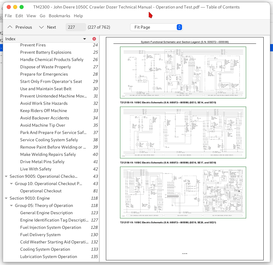
System Functional Schematic and Section Legend (S.N. 005072—005599)...225
System Functional Schematic, Wire Diagram, and Component Location Master Legend (S.N. 005600—005615)...230
System Functional Schematic and Section Legend (S.N. 005600—005615)...235
System Functional Schematic, Wire Diagram, and Component Location Master Legend (S.N. 005616— )...240
System Functional Schematic and Section Legend (S.N. 005616— )...245
Main Wire Harness (W10) and Engine Wire Harness (W13) Component Location...251
Main Wire Harness (W10) and Engine Wire Harness (W13) Wire Diagram...254
Instrument Panel Wire Harness (W11) Component Location...257
Instrument Panel Wire Harness (W11) Wire Diagram...260
Overhead Console Wire Harness (W12) Component Location...263
Overhead Console Wire Harness (W12) Wire Diagram...265
Air Conditioning Wire Harness (W14 and W15) Component Location...268
Air Conditioning Wire Harness (W14 and W15) Wire Diagram...269
Group 15: Sub-System Diagnostics...194
Power Circuit Theory of Operation...272
Starting and Charging Circuit Theory of Operation...274
Park Brake Release Circuit Theory of Operation...276
Transmission Control Unit (TCU) Operation...277
Travel Warning Alarm Theory of Operation...286
Cooling Fan Drive Circuit Theory of Operation...287
Group 17: JDG10470376 Diagnostic Test Box...194
Overview...290
JDG10470376 Diagnostic Test Box Connection...291
JDG10470376 Diagnostic Test Box Connection Troubleshooting...294
JDG10470376 Diagnostic Test Box Basic Operation...295
JDG10470376 Diagnostic Test Box Test 1—Basic Engine Controls...296
JDG10470376 Diagnostic Test Box Test 2—Transmission Control Lever (TCL)...298
JDG10470376 Diagnostic Test Box Test 3—Hydrostatic Solenoid Resistance...305
JDG10470376 Diagnostic Test Box Test 4—Engine Speed Sensor...307
JDG10470376 Diagnostic Test Box Test 5—Straight Run Test...309
JDG10470376 Diagnostic Test Box Test 6—Base Adjustment of Left Track...314
JDG10470376 Diagnostic Test Box Test 7—Adjustment of Right Track...317
Group 20: References...195
Diagnostic Trouble Code (DTC) Retrieval Procedure...325
Diagnostic Trouble Code Quick Reference List...330
Diagnostic Trouble Code (DTC)—090...335
Diagnostic Trouble Code (DTC)—111...336
Diagnostic Trouble Code (DTC)—112...337
Diagnostic Trouble Code (DTC)—121...338
Diagnostic Trouble Code (DTC)—122...339
Diagnostic Trouble Code (DTC)—211...340
Diagnostic Trouble Code (DTC)—212...341
Diagnostic Trouble Code (DTC)—250...342
Diagnostic Trouble Code (DTC)—251...343
Diagnostic Trouble Code (DTC)—252...344
Diagnostic Trouble Code (DTC)—311...345
Diagnostic Trouble Code (DTC)—312...346
Diagnostic Trouble Code (DTC)—313...347
Diagnostic Trouble Code (DTC)—321...348
Diagnostic Trouble Code (DTC)—322...349
Diagnostic Trouble Code (DTC)—323...350
Diagnostic Trouble Code (DTC)—331...351
Diagnostic Trouble Code (DTC)—332...352
Diagnostic Trouble Code (DTC)—333...353
Diagnostic Trouble Code (DTC)—341...354
Diagnostic Trouble Code (DTC)—342...355
Diagnostic Trouble Code (DTC)—343...356
Diagnostic Trouble Code (DTC)—401...357
Diagnostic Trouble Code (DTC)—402...358
Diagnostic Trouble Code (DTC)—404...359
Diagnostic Trouble Code (DTC)—405...360
Diagnostic Trouble Code (DTC)—406...361
Diagnostic Trouble Code (DTC)—407...362
JDG9796653 Diagnostic Test Box Connection...363
JDG9796653 Diagnostic Test Box Operation...367
Adjustment Checklist (S.N. 005600—006199)...391
Adjustment Checklist Quick Reference and Explanations (S.N. 005600—006199)...406
Adjustment Checklist (S.N. 006200— )...415
Adjustment Checklist Quick Reference and Explanations (S.N. 006200— )...430
Inching Pedal Test and Adjustment...439
Selected Engine Speed Sensor (R5) Adjustment...442
Electrical Component Specifications...446
DEUTSCH DEUTSCH is a trademark of the Deutsch Co. Replace Connectors...196
DEUTSCH DEUTSCH is a trademark of Deutsch Co. Replace Rectangular or Triangular Connectors...196
DEUTSCH DEUTSCH is a trademark of Deutsch Co. Install Contact...196
Amp Connector Replace Contact...456
Cannon Connector Replace Contact...459
Remove Connector Body from Blade Terminals...460
Speed Range Selector Switch Test...461
Counter Rotation Switch Test...463
Section 9020: Power Train...465
Group 05: Theory of Operation...465
Dampener Drive Operation...468
Splitter Drive Operation...470
Final Drive Operation...473
Metal Face Seal Operation...476
Group 15: Diagnostic Information...465
Diagnose Power Train Malfunctions...480
Section 9022: Pneumatic System...482
Group 05: Theory of Operation...482
Air Suspension Seat Operation...484
Group 15: Diagnostic Information...482
Air Suspension Seat Schematic...486
Section 9025: Hydraulic System...487
Group 05: Theory of Operation...487
Main Hydraulic System Relief Valves with Anti-Cavitation Operation...491
Quick-Drop Solenoid Valve Operation...493
Quick-Drop Return Cut-Off Solenoid Valve Operation...495
Float Solenoid Valve Operation...496
Fan Pump Operation...498
Fan Pump Regulator Operation...500
Reversible Fan Drive Operation (S.N. 005600— )...503
Group 15: Diagnostic Information...487
Diagnose Hydraulic System Malfunctions...515
Function Drift—Flowchart...523
Slow Hydraulics—Lift Cylinder—Flowchart...524
Slow Hydraulic Functions—Flowchart...525
Hydraulic System Noise—Flowchart...526
Dozer Hydraulic System Component Location...527
Scraper-Puller Hydraulic System Schematic...529
Ripper Hydraulic System Schematic...531
Dozer Hydraulic System Schematic...533
Group 20: Adjustments...487
Case Drain Filter Inspection...538
Main Hydraulic Pump Load Sense (LS) Adjustment...541
Main Hydraulic Pump Standby Pressure Adjustment...545
Main Hydraulic Pump Maximum Angle Stop Adjustment...548
Fan Pump Cut-Off and Standby Pressure Adjustment...549
Hydraulic Cylinder Repair Specifications...556
Group 25: Tests...487
JT05801 Clamp-On Electronic Tachometer Installation...561
JT02156A Digital Pressure/Temperature Analyzer Installation...562
Hydraulic Oil Warm-Up Procedure...563
Hydraulic System Discharging...564
Hydraulic Accumulator Discharging...565
Hydraulic Accumulator Precharge Test...566
Main Hydraulic Pump Cut-Off Pressure Test...569
Main Hydraulic Pump Load Sense (LS) Test...572
Main Hydraulic Pump Standby Pressure Test...575
Main Hydraulic System Relief Valve Test...577
Circuit Relief Valve Test...582
Main Hydraulic Pump Flow Test...587
Main Hydraulic Pump Case Drain Test...590
Pilot Control Valve Test and Adjustment...593
Fan Pump Standby Pressure Test...598
Fan Pump Cut-Off Pressure Test...600
Fan Drive Pump Case Drain Test...603
Fan Pump Flow Test (Fan Speed)...606
Lift and Tilt Cylinder Circuit Drift Test...608
Lift Cylinder Leakage Test...610
Section 9026: Hydrostatic System...613
Group 05: Theory of Operation...613
Hydrostatic Pump Operation...616
Cold Start Relief Operation...617
Charge Oil Relief Valve Operation...618
Park Brake Circuit Operation...619
Group 15: Diagnostic Information...613
Hydraulics/Hydrostatics Overheating—Flowchart...622
Low Charge Oil Pressure—Flowchart...623
Mistrack/Indexes—Flowchart...624
Machine Will Not Reach Full Speed—Flowchart...625
Low Power In One Track—Flowchart...626
Engine Starts But Machine Will Not Move—Either Side or Stops Moving—Flowchart...627
Diagnostic Test Port Component Location...628
Hydrostatic Transmission System Component Location...631
Hydrostatic Transmission System Schematic (S.N. —005599)...633
Hydrostatic Transmission System Schematic (S.N. 005600— )...636
Reversible Fan Drive System Schematic (S.N. 005600— )...639
Group 20: Adjustments...613
Hydrostatic Transmission Oil Warm-Up Procedure...642
Bleed Brake System...643
Hydrostatic Pump Neutral Adjustment...644
Group 25: Tests...613
Releasing Park Brake to Tow the Machine...648
Park Brake Towing Circuit Test...649
Park Brake Circuit Relief Valve Test and Adjustment...654
Hydrostatic Pump Neutral Position Pressure Test...659
Hydrostatic Pump High Pressure Relief Valve Test...661
Charge Oil Relief Valve Test...665
Cold Start Relief Valve Test and Adjustment...668
Charge Pump Flow Test...671
Hydrostatic Motor Case Drain Test...674
Hydrostatic Motor Operating Charge Relief Pressure Test...678
Hydrostatic Motor Minimum Angle Stop Test and Adjustment...682
Travel Speed and Straight Run Test and Adjustment (Using JDG9796653 Diagnostic Test Box)...686
Hydrostatic Motor Regulating Range Test and Adjustment (Using JDG9796653 Diagnostic Test Box)...693
Hydrostatic Pump Regulating Range Test and Adjustment (Using JDG9796653 Diagnostic Test Box)...695
Travel Speed and Straight Run Test and Adjustment (Using JDG10470376 Diagnostic Test Box)...698
Hydrostatic Pump Regulating Range Test and Adjustment (Using JDG10470376 Diagnostic Test Box)...706
Hydrostatic Motor Regulating Range Test and Adjustment (Using JDG10470376 Diagnostic Test Box)...709
Hydrostatic Motor Minimum Angle Stop Test and Adjustment (Using JDG10470376 Diagnostic Test Box)...711
Section 9031: Heating and Air Conditioning...715
Group 05: Theory of Operation...715
Air Conditioning System Cycle Of Operation...718
Air Conditioning Circuit...720
Group 15: Diagnostic Information...715
Diagnose Air Conditioning System Malfunctions...725
Diagnose Heater System Malfunctions...728
Air Conditioning Component Location...729
Group 25: Tests...715
Proper Refrigerant Handling...732
R134a Refrigerant Cautions...733
R134a Oil Charge Capacity...734
R134a Refrigerant Charge Capacity...735
Refrigerant Hoses And Tubing Inspection...736
R134a Air Conditioning System Test...737
Operating Pressure Diagnostic Chart...740
Expansion Valve Operating Test...745
Blower Motor Switch Test...747
Blower Motor Resistor Test...748
Heater Blower Motor Test...749
Air Conditioner Low Pressure Switch Test...750
Air Conditioner High Pressure Switch Test...752
Air Conditioning Air Temperature Sensor and Evaporator Temperature Sensor Test...754
Leak Testing...756
Section 9900: Dealer Fabricated Tools...757
Group 99: Dealer Fabricated Tools...757
DFT1262 Split Flange Test Plate...759
DFT1263 Split Flange Test Plate...760
John Deere 1050C Crawler Dozer Operation & Test Service Manual (TM2300)
![]()