
John Deere 755D Crawler Loader Operation and Test Service Manual (TM2366)
John Deere 755D Crawler Loader Operation and Test Service Manual (TM2366)
TM2366 - John Deere 755D Crawler Loader Technical Manual - Operation and Test.PDF
Complete Operation and Test manual with electrical wiring diagrams for John Deere 755D Crawler Loader, with all the service information to maintain, diagnose, rebuild like professional mechanics.
John Deere 755D Crawler Loader workshop Diagnosis and Test manual includes:
* Numbered table of contents easy to use so that you can find the information you need fast.
* Detailed sub-steps expand on repair procedure information
* Numbered instructions guide you through every repair procedure step by step.
* Troubleshooting and electrical service procedures are combined with detailed wiring diagrams for ease of use.
* Notes, cautions and warnings throughout each chapter pinpoint critical information.
* Bold figure number help you quickly match illustrations with instructions.
* Detailed illustrations, drawings and photos guide you through every procedure.
* Enlarged inset helps you identify and examine parts in detail.
PRODUCT DETAILS:
Total Pages: 1,016 pages
File Format: PDF (bookmarked, ToC, Searchable, Printable, high quality)
Language: English
MAIN SECTIONS
Foreword
General Information
Safety
Diagnostic Trouble Codes (DTCs)
Transmission Control Unit (TCU) Diagnostic Trouble Codes
Engine Control Unit (ECU) Diagnostic Trouble Codes
Operational Checkout Procedure
Operational Checkout Procedure
Engine
Theory of Operation
Diagnostic Information
Tests
Electrical System
System Information
System Diagrams
Sub-System Diagnostics
LinDiag® Diagnostic Application
References
Power Train
Theory of Operation
Diagnostic Information
Pneumatic System
Theory of Operation
Diagnostic Information
Hydraulic System
Theory of Operation
Diagnostic Information
Adjustments
Tests
Hydrostatic System
Theory of Operation
Diagnostic Information
Adjustments
Tests
Heating and Air Conditioning
Theory of Operation
Diagnostic Information
Tests
tm2366 - 755D Crawler Loader
Table of Contents
Foreword
Section 9000: General Information
Group 01: Safety
Recognize Safety Information
Follow Safety Instructions
Operate Only If Qualified
Wear Protective Equipment
Avoid Unauthorized Machine Modifications
Inspect Machine
Add Cab Guarding For Special Uses
Stay Clear of Moving Parts
Avoid High-Pressure Fluids
Avoid High-Pressure Oil
Beware of Exhaust Fumes
Prevent Fires
Prevent Battery Explosions
Handle Chemical Products Safely
Dispose of Waste Properly
Prepare for Emergencies
Start Only From Operator's Seat
Use and Maintain Seat Belt
Use Steps and Handholds Correctly
Add and Operate Attachments Safely
Prevent Unintended Machine Movement
Avoid Work Site Hazards
Keep Riders Off Machine
Avoid Backover Accidents
Avoid Machine Tip Over & Machine Damage
Park And Prepare For Service Safely
Service Cooling System Safely
Remove Paint Before Welding or Heating
Make Welding Repairs Safely
Drive Metal Pins Safely
Section 9001: Diagnostic Trouble Codes (DTCs)
Group 10: Transmission Control Unit (TCU) Diagnostic Trouble Codes
Transmission Control Unit (TCU) Diagnostic Trouble Codes
0250 - 24V missing, safety lever in travel position
1000 - System corruption
1010 - System Config Change
1020 - System Task Lock
1030 - Safety Relay
1031 - Emergency stop
1040 - Clock frequency fail
1050 - PLL is not locked
1060 - Watchdog shutdown
1070 - ROM Checksum
1080 - Internal selftest
1090 - No Safety Monitoring
1100 - 10V Output #1
1101 - 10V Output #2
1102 - 10V Output #3
1103 - 10V Output #4
1150 - EEProm failure
1200 - Communication SC
1300 - Type code changed
1310 - Invalid Type
2001 - MagCurrentPumpRFMin
2002 - MagCurrentPumpRFMax
2003 - MagCurrentPumpRFDif
2004 - MagCurrentPumpRFEmy
2011 - MagCurrentPumpRRMin
2012 - MagCurrentPumpRRMax
2013 - MagCurrentPumpRRDif
2014 - MagCurrentPumpRREmy
2021 - MagCurrentPumpLRMin
2022 - MagCurrentPumpLRMax
2023 - MagCurrentPumpLRDif
2024 - MagCurrentPumpLREmy
2031 - MagCurrentPumpLFMin
2032 - MagCurrentPumpLFMax
2033 - MagCurrentPumpLFDif
2034 - MagCurrentPumpLFEmy
2041 - MagCurrentMotorRMin
2042 - MagCurrentMotorRMax
2043 - MagCurrentMotorRDif
2044 - MagCurrentMotorREmy
2051 - MagCurrentMotorLMin
2052 - MagCurrentMotorLMax
2053 - MagCurrentMotorLDif
2054 - MagCurrentMotorLEmy
2070 - Brake Magnet
2071 - Overspeed Magnet
2097 - SteerPedalRight
2098 - SteerPedalLeft
2099 - Joystick_Type
2100 - Joystick_DrivePot
2101 - Joystick_Direction
2102 - Inch command
2103 - Inch device
2109 - Joystick Button
2110 - Speed switch
2111 - Engine Pot
2120 - Engine speed
2130 - Sprocket left
2140 - Sprocket right
2150 - Sprocket left+right
2160 - Pressure Sensor
2200 - SC EEProm failure
2300 - Lost Connection
2310 - Type Code Config
2400 - SC Version mismatch
2450 - Service Hydr. Fill
2500 - 24V missing, safety lever in travel position
8000 - Engine ECU Error
8001 - Engine Temperature
8002 - Engine Oil Pressure
8010 - ReverseFlowFilter
8011 - OilSupplyPressure
8012 - HydroOilTemperature
8013 - LifeTimeRight
8014 - LifeTimeLeft
8015 - Fan control
8016 - ChargeAirTemperature
8017 - Water in Fuel
8200 - CAN-Bus to ECU
8201 - CAN-RPM not received
8202 - CAN-TargRPM acknowl.
8203 - CAN-Prot. Mismatch
9000 - Safety Controller
9001 - HPumpCurrentStart-Up
9002 - HMotorCurrentStart-Up
9003 - E-Box Turns Off Device
9004 - CurrentErr R-For
9005 - CurrentErr L-For
9006 - CurrentErr R-Rev
9007 - CurrentErr L-Rev
9008 - Unintended Steering
9009 - Internal State Machine
9010 - Teach-In Error
9011 - Lost Trigger Signal
9012 - TI Illegal Curr. HP
9013 - TI Illegal Curr. HM
9014 - Illegal Steer Ratio
9015 - Fault Cur For+Rev R
9016 - Fault Cur For+Rev L
9017 - No Pump Current Right
9018 - No Pump Current Left
9019 - HMV_Current_Right_to_High
9020 - HMV_Current_Left_to_High
9021 - HMV_Current_Ratio
9022 - Teach-In_Engine_Pot
9024 - SC_Speed_Error
9025 - SC_Steering_Error
9026 - SC_Current_Error
9027 - SC_System_Error
9028 - SC_CheckStop_Error
9029 - SC_Type_Code_Error
9030 - SC_Illegal_Parameters_Error
Group 20: Engine Control Unit (ECU) Diagnostic Trouble Codes
Engine Control Unit (ECU) Diagnostic Trouble Codes
Section 9005: Operational Checkout Procedure
Group 10: Operational Checkout Procedure
Operational Checkout
Section 9010: Engine
Group 05: Theory of Operation
General Engine Description
Cold Weather Starting Aid Operation
Engine Overspeed Protection Operation
Group 15: Diagnostic Information
PowerTech Plus™ 4.5 L and 6.8 L (4045 and 6068) John Deere Engines
Engine Cooling System Component Location
Engine Fuel System Component Location
Group 25: Tests
Engine Overspeed Protection Test
Section 9015: Electrical System
Group 05: System Information
Electrical Diagram Information
Electrical Schematic Symbols
Group 10: System Diagrams
Fuse, Circuit Breaker and Relay Specifications
Load Center (A8) Variable Component Wiring
System Functional Schematic, Wire Diagram, and Component Location Master Legend (S.N. —9279)
System Functional Schematic and Section Legend (S.N. —9279)
System Functional Schematic, Wire Diagram, and Component Location Master Legend (S.N. 9280— )
System Functional Schematic and Section Legend (S.N. 9280— )
Central Harness (W10) Component Location
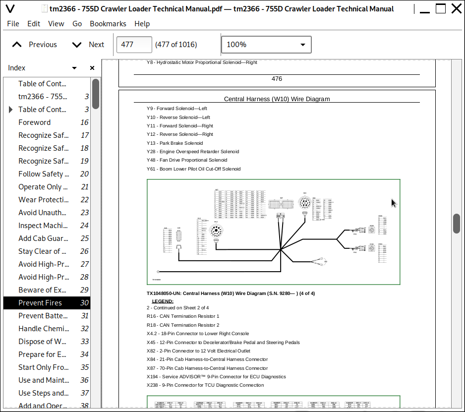
Central Harness (W10) Wire Diagram
Instrument Panel Harness (W11) Component Location
Instrument Panel Harness (W11) Wire Diagram
Cab Harness (W12) Component Location
Cab Harness (W12) Wire Diagram
Engine Harness (W13) Component Location
Engine Harness (W13) Wire Diagram
Air Conditioning Harness (W14 and W15) Component Location
Air Conditioning Harness (W14 and W15) Wire Diagram
Air Adjustable Seat Harness (W16) Component Location
Console Lower Right Harness (W17) Component Location and Wire Diagram
Group 15: Sub-System Diagnostics
Power, Starting, and Charging Circuit Theory of Operation
Park Brake Release Circuit Theory of Operation
Engine Control Unit (ECU) Theory of Operation
Transmission Control Unit (TCU) Theory of Operation
CAN Circuit Theory of Operation
Travel Warning Alarm Theory of Operation
Cooling Fan Drive Circuit Theory of Operation
Group 17: LinDiag® Diagnostic Application
LinDiag® Diagnostic Application Software Installation
USB Driver Installation
LinDiag® Diagnostic Application Connection and Startup
LinDiag® Diagnostic Application Connection Errors
LinDiag® Diagnostic Application Interface Setup
LinDiag® Diagnostic Application Language Setup
LinDiag® Diagnostic Application Report Setup
Reading Diagnostic Trouble Codes with LinDiag® Diagnostic Application
LinDiag® CAN Bus Data
Transmission Control Unit (TCU) Wire Harness Data (LinDiag v2.25)
Transmission Control Unit (TCU) Wire Harness Data (LinDiag v2.60)
LinDiag® Data Logger—Machine Recording
Machine Parameter Adjustments
Transmission Control Unit (TCU) Calibration
Transmission Control Unit (TCU) Calibration Errors
Decelerator/Brake Pedal Adjustment
Decelerator/Brake Pedal Calibration
Transmission Control Lever (TCL) Calibration
Hydrostatic Pump and Motors (Hydro) Automatic Calibration
Hydrostatic Pump and Motors (Hydro) Manual Calibration Training
Hydrostatic Pump and Motors (Hydro) Manual Calibration
Transmission Control Unit (TCU) Calibration and Parameters Reset
Transmission Control Unit (TCU) Software Install
Group 20: References
Electrical Component Specifications
Service ADVISOR™ Diagnostic Application
Service ADVISOR™ Connection Procedure
Reading Diagnostic Trouble Codes with Service ADVISOR™ Diagnostic Application
Engine Control Unit (ECU) Remove and Install
Transmission Control Unit (TCU) Remove and Install
Battery Test Procedure
Alternator Test Procedure
Temperature Sensor Test
DEUTSCH DEUTSCH is a trademark of the Deutsch Co. Replace Connectors
DEUTSCH DEUTSCH is a trademark of Deutsch Co. Replace Rectangular or Triangular Connectors
DEUTSCH DEUTSCH is a trademark of Deutsch Co. Install Contact
Amp Connector Replace Contact
Repair AMP Connector
Cannon Connector Replace Contact
Remove Connector Body from Blade Terminals
Section 9020: Power Train
Group 05: Theory of Operation
Dampener Drive Operation
Splitter Drive Operation
Final Drive Operation
Metal Face Seal Operation
Group 15: Diagnostic Information
Splitter Drive Overheating
Splitter Drive Noisy
Splitter Drive Input Or Output Shafts Not Turning
Final Drive Oil Leakage
Section 9022: Pneumatic System
Group 05: Theory of Operation
Air Suspension Seat Operation
Group 15: Diagnostic Information
Air Suspension Seat Schematic
Section 9025: Hydraulic System
Group 05: Theory of Operation
Hydraulic System Operation
Main Hydraulic Pump Operation
Hydraulic Pump Controls Operation
Main Hydraulic Control Valve Operation
Auxiliary Control Valve Operation
Pilot Control Valve Operation
Auxiliary Pilot Control Valve (PCV) Operation
Hydraulic System Relief Valve Operation
Circuit Relief Valve Operation
Boom Float Solenoid Valve Operation
Solenoid Valve Manifold Operation
Ripper Circuit Operation
Hydraulic Return Filter and Reservoir
Fan Drive Pump and Motor Circuit Operation
Group 15: Diagnostic Information
Loader Hydraulic System Component Location
Loader Hydraulic System Schematic
Ripper Hydraulic System Component Location
Ripper Hydraulic System Schematic
Multipurpose Bucket Hydraulic System Component Location
Multipurpose Bucket Hydraulic System Schematic
Fan Drive System Schematic
Fan Drive System Component Location
Case Drain Filter Inspection
No Hydraulics After Service or Repair
Slow Hydraulics After Service or Repair
No Hydraulics
Boom Will Not Raise at Slow Idle
Slow Hydraulic Functions
Hydraulic Functions Only Have One Speed
Slow Hydraulics—One Function Only
No Hydraulic Power in One Function
Hydraulic Function Makes Chattering Noise
Function Drift
Boom Float Function Does Not Work
Boom Lower Does Not Work With Engine Off
Loader Function Erratic or Jerky
Hydraulics/Hydrostatics Overheating
Hydraulic Oil Foams
Hydraulic Pump Leaking
Excessive Pump or Hydraulic System Noise
Group 20: Adjustments
Return-to-Dig Adjustment
Boom Height Limit Adjustment
Bucket Arm Linkage Inspection
Group 25: Tests
JT02156A Digital Pressure/Temperature Analyzer Installation
Hydraulic Oil Warmup Procedure
Hydraulic System Pressure Release
Hydraulic Accumulator Pressure Discharge
Hydraulic Accumulator Precharge Test
Main Hydraulic Pump Cut-Off Pressure Test and Adjustment
Main Hydraulic Pump Standby Pressure Test and Adjustment
Main Hydraulic Pump Load Sense (LS) Test
Main Hydraulic System Relief Valve Pressure Test
Circuit Relief Valve Pressure Test
Main Hydraulic Pump Flow Test
Main Hydraulic Pump Case Drain Test
Pilot Oil Pressure Test
Pilot Control Valve Pressure Test
Boom Float and Power Boost Pressure Switch Test
Auxiliary Pilot Control Valve Test
Cooling Fan Pump Pressure Test
Cooling Fan Speed Test
Cooling Fan Pump Flow Test
Boom and Bucket Cylinder Circuit Drift Test
Cylinder Leakage Test
Section 9026: Hydrostatic System
Group 05: Theory of Operation
Hydrostatic Transmission System Operation
Neutral Charge Oil Pressure Regulating Valve Operation
Charge Oil Pump Circuit Operation
Hydrostatic Oil Filtering Operation
Oil Cooler Bypass Valve Operation
Hydrostatic Transmission Control Circuit Operation
Hydrostatic Pump Operation
Hydrostatic Pump Displacement Control Operation
Multi-Function Valve Operation
Proportional Solenoid Valve Operation
Hydrostatic Motor Operation
Operating Charge Relief and Shuttle Valve Operation
Park Brake Circuit Operation
Towing Circuit Operation
Transmission Control Lever (TCL) Operation
Group 15: Diagnostic Information
Hydrostatic Transmission System Component Location
Hydrostatic Transmission System Schematic
Hydrostatic System Diagram - Park Brake On (Neutral)
Hydrostatic System Diagram - Forward (Slow Speed)
Hydrostatic System Diagram - Forward (Fast Speed)
Hydrostatic System Diagram - Reverse (Fast Speed)
Diagnostic Test Port Component Location
Oil Filter Inspection
Case Drain Filter Inspection
Hydrostatic Low/High Charge Pressure
Hydrostatic Mistrack/Indexes
Machine Will Not Reach Full Speed
Engine Starts But Both Tracks Either Do Not Move Or Come To A Stop
One Track Will Not Move
Tracks Only Move in One Direction
Group 20: Adjustments
Bleed Brake System
Park Lock Lever Adjustment
Group 25: Tests
Releasing Park Brake to Tow the Machine
Hydrostatic (HST) Oil Warmup Procedure
Hydrostatic Pump Neutral Position Pressure Test and Adjustment
Multi-Function Relief Valve Test
Charge Oil Pump Pressure Test
Charge Oil Pump Flow Test
Hydrostatic (HST) Pump Case Drain Test
Hydrostatic (HST) Motor Case Drain Test
Cooler Bypass Valve Test
Hydrostatic Motor Operating Charge Relief and Shuttle Valve Test
Hydrostatic Motor Maximum Displacement Stop Screw Test and Adjustment
Motor Displacement Control Valve Test and Adjustment
Section 9031: Heating and Air Conditioning
Group 05: Theory of Operation
Air Conditioning System Cycle Of Operation
Group 15: Diagnostic Information
Air Conditioning Component Location
Air Conditioning Circuit
Air Conditioning System Does Not Operate
Air Conditioning System Does Not Cool
Air Conditioner Runs Constantly or Only For a Short Time
System Cools Insufficiently
Noise on Air Conditioning Compressor Clutch
Heater System Does Not Operate
Heater Does Not Warm Interior of Cab
Interior Windows Continue To Fog
Group 25: Tests
Proper Refrigerant Handling
R134a Refrigerant Cautions
R134a Oil Charge Capacity
R134a Refrigerant Charge Capacity
Refrigerant Hoses And Tubing Inspection
R134a Air Conditioning System Test
Operating Pressure Diagnostic Chart
Expansion Valve Operating Test
Blower Motor Switch Test
Blower Motor Resistor Test
Heater Blower Motor Test
Air Conditioner High/Low Pressure Switch Test
Evaporator Temperature Sensor Test
Leak Testing
![]()