
John Deere Skid Steer Loaders & Compact Track Loaders 318E, 319E, 320E, 323E (Manual Controls) Repair Service Manual (TM13012X19)
Complete service repair manual for John Deere Skid Steer and Compact Track Loaders 318E, 319E, 320E, and 323E with Manual Controls and IT4/S3A engines, with all the service information to maintain, repair, and rebuild like professional mechanics.
John Deere Skid Steer Loaders & Compact Track Loaders 318E, 319E, 320E, 323E (Manual Control) workshop service repair manual includes:
* Numbered table of contents easy to use so that you can find the information you need fast.
* Detailed sub-steps expand on repair procedure information
* Numbered instructions guide you through every repair procedure step by step.
* Notes, cautions and warnings throughout each chapter pinpoint critical information.
* Bold figure number help you quickly match illustrations with instructions.
* Detailed illustrations, drawings and photos guide you through every procedure.
* Enlarged inset helps you identify and examine parts in detail.
TM13012X19 - John Deere Skid Steer Loaders & Compact Track Loaders 318E, 319E, 320E, 323E (Manual Controls) Technical Manual - Repair.pdf
TM13012X19 - John Deere Skid Steer Loaders & Compact Track Loaders 318E, 319E, 320E, 323E (Manual Controls) Technical Manual - Repair.epub
Total Pages: 643 pages
File Format: PDF/EPUB/MOBI/AZW (PC/Mac/Android/Kindle/iPhone/iPad; bookmarked, ToC, Searchable, Printable)
Language: English
MAIN SECTIONS
Foreword
Manual Identification-READ THIS FIRST!
General Information
Safety
Torque Values
Wheels (or) Tracks
Powered Wheels and Fastenings
Track System
Axles and Suspension Systems
Drive Axle Housing and Support
Axle Shaft, Bearings, and Reduction Gears
Transmission
Controls Linkage
Flywheel Coupler
Hydraulic System
Engine
Removal and Installation
Engine Auxiliary System
Cooling Systems
Intake System
External Exhaust Systems
External Fuel Supply Systems
Frame or Supporting Structure
Frame Installation
Operator's Station
Removal and Installation
Operator Enclosure
Seat and Seat Belt
Heating and Air Conditioning
Sheet Metal and Styling
Hood or Engine Enclosure
Safety and Convenience
Radio
Main Hydraulic System
Hydraulic System
Loader
Attachment Coupler
Control Linkage
Frame
Hydraulic System
Dealer Fabricated Tools
Total Pages: 679 pages
File Format: PDF (bookmarked, ToC, Searchable, Printable, high quality)
Language: English
TABLE OF CONTENTS
00 - General Information
01 - Safety
Add and Operate Attachments Safely
Avoid Backover Accidents
Avoid High-Pressure Fluids
Avoid High-Pressure Oils
Avoid Machine Tip Over
Avoid Static Electricity Risk When Refueling
Avoid Unauthorized Machine Modifications
Avoid Work Site Hazards
Clean Debris from Machine
Dispose of Waste Properly
Drive Metal Pins Safely
Follow Safety Instructions
Handle Cab Door Safely
Handle Chemical Products Safely
Inspect and Maintain ROPS
Inspect Machine
Keep Riders Off Machine
Make Welding Repairs Safely
Operate Only If Qualified
Operating On Slopes
Operating or Traveling On Public Roads
Park and Prepare for Service Safely
Prepare for Emergencies
Prevent Battery Explosions
Prevent Fires
Prevent Unintended Machine Movement
Recognize Safety Information
Remove Paint Before Welding or Heating
Service Cooling System Safely
Service Tires Safely
Start Only From Operator's Seat
Stay Clear of Moving Parts
Use and Maintain Seat Belt
Use Steps and Handholds Correctly
Wear Protective Equipment
Work In Ventilated Area
03 - Torque Values
Additional Metric Cap Screw Torque Values
Check Oil Lines And Fittings
Inch Series Four Bolt Flange Fitting For High Pressure Service Recommendations
Metric Bolt and Cap Screw Torque Values
O-Ring Face Seal Fittings With Metric Hex Nut And Stud End For High Pressure Service Recommendations
O-Ring Face Seal Fittings With Metric Hex Nut And Stud End For Standard Pressure Service Recommendations
O-Ring Face Seal Fittings With SAE Inch Hex Nut And Stud End For High Pressure Service Recommendations
Service Recommendations for 37° Flare and 30° Cone Seat Connectors
Service Recommendations For Flared Connections—Straight or Tapered Threads
Service Recommendations For Inch Series Four Bolt Flange Fittings
Service Recommendations for Metric Series Four Bolt Flange Fitting
Service Recommendations for O-Ring Boss Fittings
Unified Inch Bolt and Cap Screw Torque Values
01 - Wheels or Tracks
Drive Sprocket Remove and Install
Front Idler Yoke Assembly Remove and Install
Front or Rear Idler Remove and Install
Measure Rubber Track Height
Tire Remove and Install
Track Adjuster and Recoil Spring Assembly Remove and Install
Track Adjuster Cylinder Disassemble and Assemble
Track Adjuster Recoil Spring Remove and Install
Track Remove and Install
Track Roller Remove and Install
Wheel Remove and Install
02 - Axles and Suspension Systems
Axle Housing Disassemble and Assemble
Axle Housing Remove and Install
Chain Case Access Plate Remove and Install
Drive Chain and Sprocket Remove and Install
03 - Transmission
15 - Control Linkage
Centering Plate Inspection
Centering Plate Remove and Install
Control Lever Disassemble and Assemble
Control Lever Handle Remove and Install
Control Lever Remove and Install
Steering Cross Shaft Assembly Remove and Install
Steering Cross Shaft Disassemble and Assemble
Steering Damper Inspection
Steering Damper Remove and Install
25 - Flywheel Coupler
Hub Coupler Remove and Install
60 - Hydraulic System
Charge Pump Remove and Install
Gear Case Leakage Test
Hydrostatic and Hydraulic Start-Up Procedure
Hydrostatic Control Valve Disassemble and Assemble
Hydrostatic Control Valve Remove and Install
Hydrostatic Motor and Park Brake Assemble—Two Speed
Hydrostatic Motor and Park Brake Disassemble and Assemble
Hydrostatic Motor and Park Brake Disassemble—Two Speed
Hydrostatic Motor and Park Brake Inspection—Two Speed
Hydrostatic Motor and Park Brake Remove and Install
Hydrostatic Motor and Park Brake Remove and Install—Two Speed
Hydrostatic Motor and Park Brake Repair
Hydrostatic Motor, Park Brake, and Gear Case Assemble
Hydrostatic Motor, Park Brake, and Gear Case Disassemble
Hydrostatic Motor, Park Brake, and Gear Case Inspection
Hydrostatic Motor, Park Brake, and Gear Case Remove and Install
Hydrostatic Motor, Park Brake, and Gear Case Repair
Hydrostatic
Hydrostatic Pump Disassemble
Hydrostatic Pump Inspection
Hydrostatic Pump Remove and Install
Inspect Metal Face Seals
Measuring Park Brake Piston Movement—Two Speed
Return Manifold Screen Remove and Install
04 - Engine
Accessory Drive Belt Tensioner Remove and Install
Compressor Bracket Remove and Install
Damper Plate Remove and Install
Engine Oil Dipstick Tube Remove and Install
Engine Remove and Install
John Deere Engine
Starter Motor Remove and Install
05 - Engine Auxiliary Systems
Air Cleaner Remove and Install
Cooling Package Remove and Install
Exhaust Tube Remove and Install
Fan Remove and Install
Final Fuel Filter Assembly Remove and Install
Fuel Tank Remove and Install
Low-Pressure Fuel Pump Remove and Install
Primary Fuel Filter and Water Separator Assembly Remove and Install
Radiator Remove and Install
17 - Frames, Chassis, or Supporting Structure
Counterweight Remove and Install
Raising and Blocking Machine
Welding On Machine
Welding Repair of Major Structure
18 - Operator's Station
00 - Removal & Installation
Operator's Station Remove and Install
10 - Operator's Enclosure
Cab Door Remove and Install
Raising Operator's Station
Rear Window Remove and Install
Side Window Remove and Install
Top Window Remove and Install
21 - Seat & Seat Belt
Interlocking Seat Bar Remove and Install
Seat Air Spring Remove and Install
Seat Belt Remove and Install
Seat Remove and Install
30 - Heating & Air Conditioning System
Air Conditioner and Heater Remove and Install
Air Conditioner and Heater Remove and Install
Air Conditioner Compressor Remove and Install
Blower Fan Remove and Install
Charge R134a System
Condenser Remove and Install
Evacuate R134a System
Evaporator Remove and Install
Expansion Valve Remove and Install
Flush and Purge Air Conditioner System
Heater Core Remove and Install
R134a Refrigerant Oil Information
R134a Refrigerant Oil Information
R134a Refrigerant Recovery, Recycling, and Charging Station Installation Procedure
R134a Refrigerant Recovery, Recycling, and Charging Station Installation Procedure
Receiver-Dryer Remove and Install
Recover R134a Refrigerant
Refrigerant Cautions and Proper Handling
Refrigerant Cautions and Proper Handling
19 - Sheet Metal and Styling
Engine Cover Remove and Install
Footwell Remove and Install
Side Panel Remove and Install
20 - Safety, Convenienence and Miscellaneous
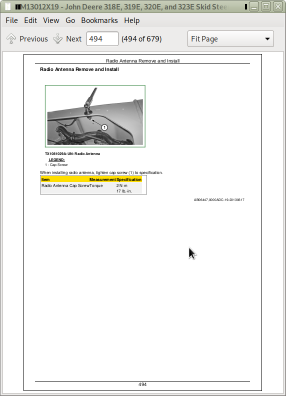
Radio Antenna Remove and Install
21 - Main Hydraulic System
General Oil Cleanup Procedure
High Flow Hydraulic Pump Disassemble and Assemble
Hydraulic Fan Motor Remove and Install
Hydraulic _ Hydrostatic Component Failure Cleanup Procedure
Hydraulic Oil Cooler Remove and Install
Hydraulic Oil Reservoir Remove and Install
Hydraulic Pump Disassemble and Assemble
Hydraulic Pump Remove and Install
Vacuum Pump Installation
31 - Loader
04 - Attachment Coupler
Quik-Tatch™ Actuator Remove and Install
Quik-Tatch™ Coupler Remove and Install
15 - Control Linkages
Hand Control Linkage Remove and Install
Pedal Assembly Disassemble and Assemble
Pedal Assembly Remove and Install
40 - Frames
Boom Lock Disassemble and Assemble
Boom Lock
Boom Lock Remove and Install
Boom Remove and Install
Lower Boom Link Remove and Install
Upper Boom Link Remove and Install
60 - Hydraulic Systems
Boom Cylinder Remove and Install
Bucket Cylinder Remove and Install
Control Valve Disassemble and Assemble
Control Valve Remove and Install
Hydraulic Cylinder Bleed Procedure
Hydraulic Cylinder Disassemble and Assemble
Hydraulic Oil Filter Manifold Remove and Install
Ride Control Accumulator Remove and Install
Ride Control Valve Disassemble and Assemble
Ride Control Valve Remove and Install
Self Leveling Valve Remove and Install
99 - Dealer Fabricated Tools
DFT1087 Track Recoil Spring Disassembly and Assembly Guard Tool
DFT1101 Boom Lifting Bracket
DFT1325 Solenoid Power Harness
DFT1333 Lock Nut Wrench
DFT1334 Gear Case Turning Tool
DFT1335 Park Brake Spring Compressor
DFT1336 Bias Spring Compressor
DFT1358 Engine Lifting Bracket
DFT1359 Engine Lifting Bracket
JT38077 Boom Pin Driver
ST4920 Track Recoil Spring Disassembly and Assembly Tool
John Deere Skid Steer Loaders & Compact Track Loaders 318E, 319E, 320E, 323E (Manual Controls) Repair Service Manual (TM13012X19)
![]()