
John Deere 329E and 333E Compact Track Loaders Repair Service Manual (TM12808)
Complete service repair manual for John Deere 329E and 333E Compact Track Loaders, with all the workshop information to maintain, repair, and service like professional mechanics.
John Deere 329E and 333E Compact Track Loaders workshop service & repair manual includes:
* Numbered table of contents easy to use so that you can find the information you need fast.
* Detailed sub-steps expand on repair procedure information
* Numbered instructions guide you through every repair procedure step by step.
* Bold figure number help you quickly match illustrations with instructions.
* Detailed illustrations, drawings and photos guide you through every procedure.
* Enlarged inset helps you identify and examine parts in detail.
TM12808 - John Deere 329E and 333E Compact Track Loaders Technical Manual - Repair.pdf
TM12808 - John Deere 329E and 333E Compact Track Loaders Technical Manual - Repair.epub
Total Pages: 614 pages
File Format: PDF/EPUB/MOBI/AZW (PC/Mac/Android/Kindle/iPhone/iPad; bookmarked, ToC, Searchable, Printable)
Language: English
MAIN SECTIONS
Foreword
Manual Identification
00 - General Information
01 - Wheels or Tracks
02 - Axles and Suspension Systems
03 - Transmission
04 - Engine
05 - Engine Auxiliary System
17 - Frame or Supporting Structure
18 - Operator's Station
19 - Sheet Metal and Styling
20 - Safety and Convenience
21 - Main Hydraulic System
31 - Loader
99 - Dealer Fabricated Tools
Total Pages: 645 pages
File Format: PDF (bookmarked, ToC, Searchable, Printable, high quality)
Language: English
328E (PIN: 1T0328E***E236673-)
329E (PIN: 1T0329E***E236704-)
332E (PIN: 1T0332E***E236670-)
333E (PIN: 1T0333E***E236690-)
Foreword
Manual Identification-READ THIS FIRST!
General Information
Safety
Torque Values
Wheels or Tracks
Powered Wheels and Fastenings
Track System
Axles and Suspension Systems
Drive Axle Housing and Support
Axle Shaft, Bearings, and Reduction Gears
Transmission
Controls Linkage
Flywheel Coupler
Hydraulic System
Engine
Removal and Installation
Engine Auxiliary System
Cooling Systems
Intake System
External Exhaust Systems
External Fuel Supply Systems
Frame or Supporting Structure
Frame Installation
Operator's Station
Removal and Installation
Operator Enclosure
Seat and Seat Belt
Heating and Air Conditioning
Sheet Metal and Styling
Hood or Engine Enclosure
Safety and Convenience
Radio
Main Hydraulic System
Hydraulic System
Loader
Attachment Coupler
Frame
Hydraulic System
Dealer Fabricated Tools
TABLE OF CONTENTS - Exploded View
00 - General Information
0001 - Safety
Add and Operate Attachments Safely
Avoid Backover Accidents
Avoid High-Pressure Fluids
Avoid High-Pressure Oils
Avoid Machine Tip Over
Avoid Unauthorized Machine Modifications
Avoid Work Site Hazards
Clean Debris from Machine
Clean Exhaust Filter Safely
Dispose of Waste Properly
Drive Metal Pins Safely
Follow Safety Instructions
Handle Cab Door Safely
Handle Chemical Products Safely
Inspect and Maintain ROPS
Inspect Machine
Keep Riders Off Machine
Make Welding Repairs Safely
Operate Only If Qualified
Operating On Slopes
Operating or Traveling On Public Roads
Park and Prepare for Service Safely
Prepare for Emergencies
Prevent Battery Explosions
Prevent Fires
Prevent Unintended Machine Movement
Recognize Safety Information
Remove Paint Before Welding or Heating
Service Cooling System Safely
Start Only From Operator's Seat
Stay Clear of Moving Parts
TX1064889-UN Operate on Solid Footing
Use and Maintain Seat Belt
Use Steps and Handholds Correctly
Wear Protective Equipment
Work In Ventilated Area
0003 - Torque Values
Additional Metric Cap Screw Torque Values
Check Oil Lines And Fittings
H70406-UN O-Ring Face Seal Fitting
Inch Series Four Bolt Flange Fitting For High Pressure Service Recommendations
Metric Bolt and Screw Torque Values
O-Ring Face Seal Fittings With Metric Hex Nut And Stud End For High Pressure Service Recommendations
O-Ring Face Seal Fittings With Metric Hex Nut And Stud End For Standard Pressure Service Recommendations
O-Ring Face Seal Fittings With SAE Inch Hex Nut And Stud End For High Pressure Service Recommendations
Service Recommendations for 37302260 Flare and 30302260 Cone Seat Connectors
Service Recommendations For Flared Connections342200224Straight or Tapered Threads
Service Recommendations For Inch Series Four Bolt Flange Fittings
Service Recommendations for Metric Series Four Bolt Flange Fitting
Service Recommendations for O-Ring Boss Fittings
T196337-UN O-Ring Face Seal Fittings
T6890BB-UN Flange Fittings
T6890BB-UN Four Bolt Flange Fittings
T6890BB-UN Metric Series Four Bolt Flange Fitting
TS1670-UN Metric Bolt and Screw
TS1671-UN Unified Inch Bolt and Screw
Unified Inch Bolt and Screw Torque Values
01 - Wheels or Tracks
0110 - Powered Wheels and Fastening
Tire Remove and Install
Wheel Remove and Install
0130 - Track System
Drive Sprocket Remove and Install
Front Idler Yoke Assembly Remove and Install
Front or Rear Idler Remove and Install
Measure Rubber Track Height
T213966-UN Track Lug Measurement
Track Adjuster and Recoil Spring Assembly Remove and Install
Track Adjuster Cylinder Disassemble and Assemble
Track Adjuster Recoil Spring Remove and Install
Track Remove and Install
02 - Axles and Suspension Systems
0201 - Drive Axle Housing and Support
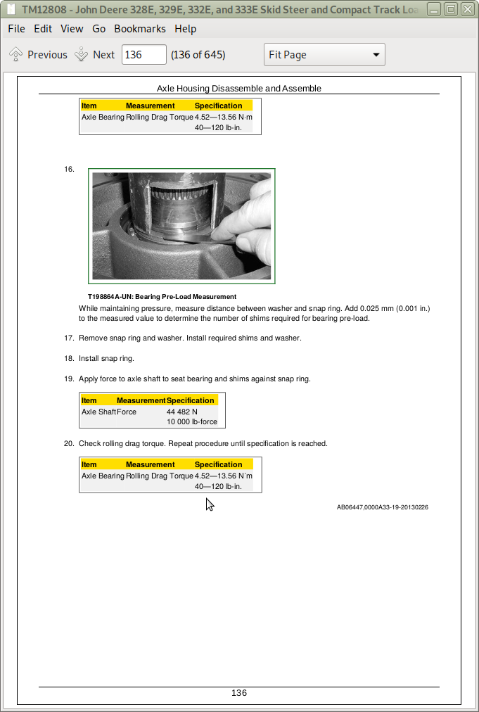
Axle Housing Disassemble and Assemble
Axle Housing Remove and Install
TX1068755-UN Axle Housing Assembly
0250 - Axle Shaft, Bearing, and Reduction Gears
Chain Case Access Plate Remove and Install
Drive Chain and Sprocket Remove and Install
03 - Transmission
0315 - Controls Linkage
Joystick Disassemble and Assemble
Left and Right Joystick Remove and Install
0325 - Flywheel Coupler
Hub Coupler Remove and Install
0360 - Hydraulic System
Charge Pump Remove and Install
Gear Case Leakage Test
Hydrostatic and Hydraulic Start-Up Procedure
Hydrostatic Control Valve Disassemble and Assemble
Hydrostatic Control Valve Remove and Install
Hydrostatic Motor and Park Brake Disassemble and Assemble
Hydrostatic Motor and Park Brake Disassemble and Assemble342200224Two Speed
Hydrostatic Motor and Park Brake Remove and Install
Hydrostatic Motor, Park Brake, and Gear Case Assemble
Hydrostatic Motor, Park Brake, and Gear Case Disassemble
Hydrostatic Motor, Park Brake, and Gear Case Inspection
Hydrostatic Motor, Park Brake, and Gear Case Remove and Install
Hydrostatic Motor, Park Brake, and Gear Case Repair
Hydrostatic Pump Disassemble and Assemble
Hydrostatic Pump Remove and Install
Inspect Metal Face Seals
Park Brake Solenoid Valve Remove and Install
Return Manifold Screen Remove and Install
T200169-UN Wheel Motor Assembly
TX1034354-UN Electric Displacement Control
TX1034355-UN Hydrostatic Pump Section (right side pump shown)
TX1034356-UN Center Manifold
TX1081729A-UN Gear Case Leakage Test
TX1081820A-UN Gear Case
TX1082027-UN Gear Case Components
TX1131658A-UN Hydrostatic Motor and Park Brake (left side shown)
TX1132085-UN Worn Seal Rings
TX1132086-UN Seal Ring
TX1132505A-UN Hydrostatic Control Valve
TX1134872A-UN Drive Chains and Sprocket
04 - Engine
0400 - Removal and Installation
Accessory Drive Belt Tensioner Remove and Install
Compressor Bracket Remove and Install
Damper Plate Remove and Install
Engine Oil Dipstick Tube Remove and Install
Engine Remove and Install
John Deere Engine
Starter Motor Remove and Install
05 - Engine Auxiliary System
0510 - Cooling System
Charge Air Cooler Remove and Install
Cooling Package Remove and Install
Fan Remove and Install
Radiator Remove and Install
0520 - Intake System
Air Cleaner Remove and Install
0530 - Extend Exhaust System
Diesel Particulate Filter (DPF) Remove and Install
Exhaust Filter Remove and Install
Exhaust Tube Remove and Install
TX1137806-UN Exhaust Filter
0560 - External Fuel Supply Systems
Final Fuel Filter Assembly Remove and Install
Fuel Tank Remove and Install
Low-Pressure Fuel Pump Remove and Install
Primary Fuel Filter and Water Separator Assembly Remove and Install
17 - Frame or Supporting Structure
1740 - Frame Installation
Counterweight Remove and Install
Raising and Blocking Machine
Welding On Machine
Welding Repair of Major Structure
18 - Operator's Station
1800 - Removal and Installation
Operator's Station Remove and Install
TX1132163A-UN Operator's Station Isolator
1810 - Operator Enclose
Cab Door Remove and Install
Raising Operator's Station
Rear Window Remove and Install
Side Window Remove and Install
Top Window Remove and Install
TX1069889-UN Rear Window Seal
TX1136097-UN Right Side Window
1821 - Seat and Seat Belt
Interlocking Seat Bar Remove and Install
Seat Air Spring Remove and Install
Seat Belt Remove and Install
Seat Remove and Install
TX1111725-UN Air Hose Installation
TX1136106-UN Air Spring Assembly
19 - Sheet Metal and Styling
1910 - Hood or Engine Enclosure
Engine Cover Remove and Install
Footwell Remove and Install
Side Panel Remove and Install
20 - Safety and Convenience
2001 - Radio
Radio Antenna Remove and Install
21 - Main Hydraulic System
2160 - Hydraulic System
General Oil Cleanup Procedure
Hydraulic Fan Motor Remove and Install
HydraulicHydrostatic Component Failure Cleanup Procedure
Hydraulic Oil Cooler Remove and Install
Hydraulic Oil Reservoir Remove and Install
Hydraulic Pump Disassemble and Assemble
Hydraulic Pump Remove and Install
TX1132812A-UN Hydraulic Pumps and Lines (high flow shown)
TX1134950-UN Hydraulic Oil Reservoir
TX1135764A-UN Charge Pump Components
TX1135765A-UN Hydraulic Pump Section
TX1135766A-UN Hydraulic Pump and Drive Components
Vacuum Pump Installation
31 - Loader
3104 - Attachment Coupler
Quik-Tatch342204242 Actuator Remove and Install
Quik-Tatch342204242 Coupler Remove and Install
3140 - Frame
Boom Lock Disassemble and Assemble
Boom Lock
Boom Lock Remove and Install
Boom Remove and Install
Lower Boom Link Remove and Install
TX1136331-UN Upper Boom Link Assembly
TX1136995A-UN Frame Pin Removal
Upper Boom Link Remove and Install
3160 - Hydraulic System
Boom Cylinder Remove and Install
Bucket Cylinder Remove and Install
Control Valve Disassemble and Assemble
Control Valve Remove and Install
Hydraulic Cylinder Bleed Procedure
Hydraulic Cylinder Disassemble and Assemble
Hydraulic Oil Filter Manifold Remove and Install
Ride Control Accumulator Remove and Install
Ride Control Valve Disassemble and Assemble
Ride Control Valve Remove and Install
Self Leveling Valve Remove and Install
TX1135605A-UN Ride Control Vale Fittings
TX1135665A-UN Valve O-Rings
TX1135758A-UN Ride Control Valve Assembly
99 - Dealer Fabricated Tools
9900 - Dealer Fabricated Tools
DFT1087 Track Recoil Spring Disassembly and Assembly Guard Tool
DFT1101 Boom Lifting Bracket
DFT1325 Solenoid Power Harness
DFT1333 Lock Nut Wrench
DFT1334 Gear Case Turning Tool
DFT1335 Park Brake Spring Compressor
DFT1336 Bias Spring Compressor
DFT1358 Engine Lifting Bracket
DFT1359 Engine Lifting Bracket
ST4920 Track Recoil Spring Disassembly and Assembly Tool
T6585UY-UN ST4920 Track Recoil Spring Tool Parts
T7029CG-UN Track Recoil Spring Tool Dimensions
T7029CH-UN Track Recoil Spring Tool Dimensions
T7029CI-UN Track Recoil Spring Tool Dimensions
T7162AF-UN Recoil Spring Guard Tool Dimensions
TX1070702-UN DFT1101 Boom Lifting Bracket
TX1076018A-UN DFT1325 Solenoid Power Harness
TX1080428-UN DFT1333 Lock Nut Wrench
TX1080429-UN DFT1335 Park Brake Spring Compressor
TX1080645A-UN DFT1334 Gearbox Turning Tool
TX1133848-UN DFT1359 Engine Lifting Bracket
TX1133849-UN DFT1358 Engine Lifting Bracket
John Deere 329E and 333E Compact Track Loaders Repair Service Manual (TM12808)
![]()