
John Deere Skid Steer Loaders 325, 328 Operation and Test Service Manual (TM2191)
Complete Operation and Test manual with Electrical Wiring Diagrams for John Deere Skid Steer Loaders 325, 328, with all the technical information to maintain, diagnose, and service like professional mechanics.
John Deere Skid Steer Loaders 325, 328 workshop Operation and Test manual includes:
* Numbered table of contents easy to use so that you can find the information you need fast.
* Detailed sub-steps expand on Operation and Test procedure information
* Numbered instructions guide you through every repair procedure step by step.
* Troubleshooting and electrical service procedures are combined with detailed wiring diagrams for ease of use.
* Notes, cautions and warnings throughout each chapter pinpoint critical information.
* Bold figure number help you quickly match illustrations with instructions.
* Detailed illustrations, drawings and photos guide you through every procedure.
* Enlarged inset helps you identify and examine parts in detail.
TM2191 - John Deere 325 and 328 Skid Steer Loader Technical Manual - Operation and Test.PDF
TM2191 - John Deere 325 and 328 Skid Steer Loader Technical Manual - Operation and Test.EPUB
Total Pages: 1,213 pages
File Format: PDF/EPUB/MOBI/AZW (PC/Mac/Android/Kindle/iPhone/iPad; bookmarked, ToC, Searchable, Printable)
Language: English
MAIN SECTIONS
Foreword
Technical Information Feedback Form
General Information
Safety
Diagnostic Trouble Codes (DTCs)
Engagement and Monitor Unit (EMU) Diagnostic Trouble Codes
Hydraulic Control Unit (HCU) Diagnostic Trouble Codes
Left Joystick Controller (JSL)
Right Joystick Controller (JSR)
Operational Checkout Procedure
Operational Checkout Procedure
Engine
Theory Of Operation
Diagnose Observable Machine Symptoms
Tests
Electrical System
System Information
System Diagrams
Sub-System Diagnostics
References
Power Train
Theory Of Operation
Diagnostic Information
Tests
Hydraulic System
Theory Of Operation
Diagnostic Information
Tests
Hydrostatic System
Theory Of Operation
Diagnostic Information
Tests
Heating and Air Conditioning
Theory Of Operation
Diagnostic Information
Tests
Dealer Fabricated Tools
tm2191 - 325 and 328 Skid Steer Loader
Table of Contents
Foreword
Technical Information Feedback Form
Section 9000: General Information
Group 01: Safety
Recognize Safety Information
Follow Safety Instructions
Operate Only If Qualified
Wear Protective Equipment
Avoid Unauthorized Machine Modifications
Inspect Machine
Stay Clear of Moving Parts
Avoid High-Pressure Oils
Beware of Exhaust Fumes
Prevent Fires
Prevent Battery Explosions
Handle Chemical Products Safely
Dispose of Waste Properly
Prepare for Emergencies
Use Steps and Handholds Correctly
Start Only From Operator's Seat
Use and Maintain Seat Belt
Prevent Unintended Machine Movement
Avoid Work Site Hazards
Keep Riders Off Machine
Avoid Backover Accidents
Avoid Machine Tip Over
Operating or Traveling On Public Roads
Add and Operate Attachments Safely
Park And Prepare For Service Safely
Service Cooling System Safely
Remove Paint Before Welding or Heating
Make Welding Repairs Safely
Drive Metal Pins Safely
Section 9001: Diagnostic Trouble Codes (DTCs)
Group 10: Engagement and Monitor Unit (EMU) Diagnostic Trouble Codes
Engagement and Monitor Unit (EMU) Diagnostic Trouble Codes—Standard Controls
F9D0 - Coolant Temperature Sensor Input at 0 Volts
F9D5 - Coolant Temperature Sensor Input at 5 Volts
F965 - Fuel Level Sensor Input at 5 Volts
F974 - Alternator Voltage Out of Range High
F980 - Hydraulic Oil Temperature Sensor Input at 0 Volts
F985 - Hydraulic Oil Temperature Sensor Input at 5 Volts
F9P8 - Park Brake Output Open or Shorted to Power
F9P9 - Park Brake Output Shorted to Ground
F9H8 - Hydraulic Output Open or Hydraulic Output Shorted to Power
F9H9 - Hydraulic Output Shorted to Ground
F9J8 - Glow Plug Relay Output Open or Shorted to Power
F9J9 - Glow Plug Relay Output Shorted to Ground
F9K8 - Auto Shutdown Relay Output Open or Shorted to Power
F9K9 - Auto Shutdown Relay Output Shorted to Ground
F9M9 - Engagement and Monitor Unit (EMU) Warning Alarm Output Shorted to Ground
Engagement and Monitor Unit (EMU) Diagnostic Trouble Codes—EH Controls
000070.02 - Park Brake Release Input Erratic or Bad Data
000070.04 - Park Brake Release Input Out of Range Low
000096.03 - Fuel Level Sensor Out of Range High
000096.04 - Fuel Level Sensor Out of Range Low
000100.01 - Engine Oil Pressure Data Below Normal
000100.03 - Engine Oil Pressure Out of Range High
000107.00 - Engine Air Filter Switch Data Above Normal
000107.03 - Engine Air Filter Switch Out of Range High
000110.00 - Engine Coolant Temperature Data Above Normal
000110.03 - Engine Coolant Temperature Out of Range High
000110.04 - Engine Coolant Temperature Out of Range Low
000158.00 - System Voltage Data Above Normal
000158.01 - System Voltage Data Below Normal
000162.04 - 2-Speed Switch Input Out of Range Low
000676.05 - Glow Plug Relay Output Out of Range Low
000676.06 - Glow Plug Relay Output Out of Range High
000920.05 - Alarm Output Out of Range Low
000920.06 - Alarm Output Out of Range High
001347.05 - Fuel Valve Relay Output Out of Range Low
001347.06 - Fuel Valve Relay Output Out of Range High
001504.04 - Seat Switch Input Out of Range Low
001508.00 - Hydraulic Oil Temperature Data Above Normal
001508.03 - Hydraulic Oil Temperature Out of Range High
001508.04 - Hydraulic Oil Temperature Out of Range Low
001550.05 - AC Compressor Clutch Output Out of Range Low
001550.06 - AC Compressor Clutch Output Out of Range High
001713.00 - Hydraulic Filter Restriction Switch Data Above Normal
001713.03 - Hydraulic Oil Filter Out of Range High
001856.04 - Seat Belt Switch Input Out of Range Low
002228.09 - No HCU Data on CAN Bus Abnormal Data Range
003413.04 - Door Switch Input Out of Range Low
003597.03 - 5 Volt Sensor Supply 1 Out of Range High
003597.04 - 5 Volt Sensor Supply 1 Out of Range Low
520194.13 - Machine Model ID Wrong or Missing Calibrate Error
520850.04 - Over Ride Switch Input Out of Range Low
521050.04 - Aux Flow On-Off Switch Input Out of Range Low
522379.05 - Park Brake Release Output Out of Range Low
522379.06 - Park Brake Release Output Out of Range High
522398.02 - Park Brake Run Switch Input Erratic or Bad Data
522398.04 - Park Brake Run Switch Input Out of Range Low
523217.06 - Hydraulic Valve Power 3 to HCU Out of Range High
523218.06 - Propel Valve Power 2 to HCU Out of Range High
523219.06 - Hydraulic Valve Power 1 to HCU Out of Range High
523693.03 - Aux Hyd Channel 1 Input Out of Range High
523693.04 - Aux Hyd Channel 1 Input Out of Range Low
523694.03 - Aux Hyd Channel 2 Input Out of Range High
523694.04 - Aux Hyd Channel 2 Input Out of Range Low
523694.12 - Aux Hyd Channel 2 Input Device Fault
523917.05 - Two Speed Output Out of Range Low
523917.06 - Two Speed Output Out of Range High
523935.05 - Aux Hyd Extend Output Out of Range Low
523935.06 - Aux Hyd Extend Output Out of Range High
523941.05 - Aux Hyd Retract Output Out of Range Low
523941.06 - Aux Hyd Retract Output Out of Range High
524225.04 - Remote Start Input Out of Range Low
524264.11 - Checksum Error Unknown Fault
Group 20: Hydraulic Control Unit (HCU) Diagnostic Trouble Codes
Hydraulic Control Unit (HCU) Diagnostic Trouble Codes
000091.03 - Throttle Sensor Out of Range High
000091.04 - Throttle Sensor Out of Range Low
000091.16 - Throttle Sensor Moderately High Value
000091.18 - Throttle Sensor Moderately Low Value
000168.03 - Unswitched Power Input Out of Range High
000168.04 - Unswitched Power Input Out of Range Low
000190.12 - Engine Speed Sensor Device Fault
000237.02 - Vehicle Identification Erratic or Bad Data
001594.00 - Left Speed Sensor Input Data Above Normal
001594.01 - Left Speed Sensor Input Data Below Normal
001594.02 - Left Speed Sensor Input Erratic or Bad Data
001594.14 - Left Speed Sensor Input
001595.00 - Right Speed Sensor Input Data Above Normal
001595.01 - Right Speed Sensor Input Data Below Normal
001595.14 - Right Speed Sensor Input
002201.09 - Right Joystick CAN Data Abnormal Data Rate
002213.09 - Left Joystick CAN Data Abnormal Data Rate
002392.05 - Backup Alarm Output Out of Range Low
002660.07 - Right Joystick X-axis Mechanical Fault
002661.07 - Right Joystick Y-axis Mechanical Fault
002697.07 - Left Joystick Mechanical Fault
002698.07 - Left Joystick Mechanical Fault
003597.03 - 5 Volt Sensor Supply 1 Out of Range High
003597.04 - 5 Volt Sensor Supply 1 Out of Range Low
003597.03 - 5 Volt Sensor Supply 2 Out of Range High
003597.04 - 5 Volt Sensor Supply 2 Out of Range Low
520652.05 - Bucket Curl Solenoid Current Out of Range Low
520652.06 - Bucket Curl Solenoid Current Out of Range High
520652.16 - Bucket Curl Solenoid Current Moderately High Value
520653.05 - Bucket Dump Solenoid Current Out of Range Low
520653.06 - Bucket Dump Solenoid Current Out of Range High
520653.16 - Bucket Dump Solenoid Current Moderately High Value
520849.04 - Float Switch Input Out of Range Low
522447.05 - Right Pump Fwd Sol Current Out of Range Low
522447.06 - Right Pump Fwd Sol Current Out of Range High
522447.16 - Right Pump Fwd Sol Current Moderately High Value
522448.05 - Right Pump Rev Sol Current Out of Range Low
522448.06 - Right Pump Rev Sol Current Out of Range High
522448.16 - Right Pump Rev Sol Current Moderately High Value
522449.05 - Left Pump Rev Sol Current Out of Range Low
522449.06 - Left Pump Rev Sol Current Out of Range High
522449.16 - Left Pump Rev Sol Current Moderately High Value
522450.05 - Left Pump Fwd Sol Current Out of Range Low
522450.06 - Left Pump Fwd Sol Current Out of Range High
522450.16 - Left Pump Fwd Sol Current Moderately High Value
523217.03 - Hydraulic Valve Power 3 to HCU Out of Range High
523217.04 - Hydraulic Valve Power 3 to HCU Out of Range Low
523218.03 - Propel Valve Power 2 to HCU Out of Range High
523218.04 - Propel Valve Power 2 to HCU Out of Range Low
523219.03 - Hydraulic Valve Power 1 to HCU Out of Range High
523219.04 - Hydraulic Valve Power 1 to HCU Out of Range Low
523411.05 - Boom Down Solenoid Current Out of Range Low
523411.06 - Boom Down Solenoid Current Out of Range High
523411.16 - Boom Down Solenoid Current Moderately High Value
523414.05 - Boom Up Solenoid Current Out of Range Low
523414.06 - Boom Up Solenoid Current Out of Range High
523414.16 - Boom Up Solenoid Current Moderately High Value
523426.05 - Hyd Port Lock Solenoid Current Out of Range Low
523426.06 - Hyd Port Lock Solenoid Current Out of Range High
524264.11 - Checksum Error Unknown Fault
Group 30: Left Joystick Controller (JSL)
Left Joystick Controller (JSL) Diagnostic Trouble Codes
002697.03 - Left Joystick X-axis Out of Range High
002697.04 - Left Joystick X-axis Out of Range Low
002697.13 - Left Joystick X-axis Calibration Error
002697.14 - Left Joystick X-axis Sensor Redundancy Error
002698.03 - Left Joystick Y-axis Out of Range High
002698.04 - Left Joystick Y-axis Out of Range Low
002698.13 - Left Joystick Y-axis Calibration Error
002698.14 - Left Joystick Y-axis Sensor Redundancy Error
Group 40: Right Joystick Controller (JSR)
Right Joystick Controller (JSR) Diagnostic Trouble Codes
002660.03 - Right Joystick X-axis Out of Range High
002660.04 - Right Joystick X-axis Out of Range Low
002660.13 - Right Joystick X-axis Calibration Error
002660.14 - Right Joystick X-axis Redundancy Error
002661.03 - Right Joystick Y-axis Out of Range High
002661.04 - Right Joystick Y-axis Out of Range Low
002661.13 - Right Joystick Y-axis Calibration Error
002661.14 - Right Joystick Y-axis Sensor Redundancy Error
Section 9005: Operational Checkout Procedure
Group 10: Operational Checkout Procedure
Operational Checkout
Section 9010: Engine
Group 05: Theory Of Operation
POWERTECH POWERTECH is a trademark of Deere & Company 2.4 L & 3.0 L (4024 & 5030) John Deere Engines
Group 15: Diagnose Observable Machine Symptoms
2.4 L & 3.0 L Diesel Engine for 325 & 328 Skid Steer Loader
Engine Fuel System Component Location
Group 25: Tests
Engine Speed Test and Adjustment
Engine Power Test Using Turbocharger Boost Pressure
Section 9015: Electrical System
Group 05: System Information
Electrical Diagram Information
Electrical Schematic Symbols
Group 10: System Diagrams
Fuse Specifications
System Functional Schematic, Wiring Diagram, and Component Location Master Legend
System Functional Schematic and Section Legend
System Functional Schematic, Wiring Diagram, and Component Location Master Legend—EH Controls
System Functional Schematic and Section Legend—EH Controls
Engine Harness (W1) Component Location
Engine Harness (W1) Wiring Diagram
Cab Harness—Standard (W2) Component Location
Cab Harness—Standard (W2) Wiring Diagram
Front Chassis Harness—Standard (W3) Component Location
Front Chassis Harness—Standard (W3) Wiring Diagram
Backup Alarm Harness (W4) Component Location
Backup Alarm Harness (W4) Wiring Diagram
Dual Flasher Harness (W5) Component Location
Dual Flasher Harness (W5) Wiring Diagram
Horn Harness (W6) Component Location
Horn Harness (W6) Wiring Diagram
Air Conditioner and Heater Harness (W7) Component Location
Air Conditioner and Heater Harness (W7) Wiring Diagram
Wiper Harness (W8) Component Location
Wiper Harness (W8) Wiring Diagram
12 Volt Auxiliary Power Harness (W9) Component Location
12 Volt Auxiliary Power Harness (W9) Wiring Diagram
Beacon Harness (W10) Component Location
Beacon Harness (W10) Wiring Diagram
Cab Harness—Deluxe (W12) Component Location
Cab Harness—Deluxe (W12) Wiring Diagram
Front Chassis Harness—Deluxe (W13) Component Location
Front Chassis Harness—Deluxe (W13) Wiring Diagram
8-Button Controller Harness (W15) Component Location
8-Button Controller Harness (W15) Wiring Diagram
Operator Convenience Package Harnesses (W18 and W19) Component Location
Operator Convenience Package Harnesses (W18 and W19) Wiring Diagram
Electric Quik-Tatch (W28) Component Location (S.N. 131877— )
Electric Quik-Tatch (W28) Wiring Diagram (S.N. 131877— )
Helper Fan Control and Tee Harness (W29 and W30) Component Location
Helper Fan Control and Tee Harness (W29 and W30) Wiring Diagram
Engine Harness—EH Controls (W31) Component Location
Engine Harness—EH Controls (W31) Wiring Diagram
Cab Harness—EH Controls (W32) Component Location
Cab Harness—EH Controls (W32) Wiring Diagram
Backup Alarm Harness—EH Controls (W33) Component Location
Backup Alarm Harness—EH Controls (W33) Wiring Diagram
Horn Harness—EH Controls (W34) Component Location
Horn Harness—EH Controls (W34) Wiring Diagram
Electrohydraulic Controller Harness (W35) Component Location
Electrohydraulic Controller Harness (W35) Wiring Diagram
Attachment Control Harness (W36) Component Location—If Equipped
Attachment Control Harness (W36) Wiring Diagram—If Equipped
Water-in-Fuel Indicator Harness (W37) and Water-in-Fuel Sensor Harness (W38) Component Location—If Equipped
Water-in-Fuel Indicator Harness (W37) Wiring Diagram—If Equipped
Water-in-Fuel Sensor Harness (W38) Wiring Diagram—If Equipped
License Plate Light Harness (W39) Component Location—If Equipped
License Plate Light Harness (W39) Wiring Diagram—If Equipped
Group 15: Sub-System Diagnostics
Starting Circuit Theory of Operation
Engagement and Monitor Unit Circuit Theory of Operation
Engagement and Monitor Unit Circuit Theory of Operation—EH Controls
Electrohydraulic Controls Circuit Theory of Operation
Backup Alarm Circuit Theory of Operation
Backup Alarm Circuit Theory of Operation—EH Controls
Electric Quik-Tatch Theory of Operation (S.N. 131877— )
Group 20: References
Engagement and Monitor Unit Operation
Engagement and Monitor Unit Operation—EH Controls
Anti-Theft Security System Operation—If Equipped
Anti-Theft Security System Configuration—EH Controls
Anti-Theft Security System Operation—EH Controls—If Equipped
Anti-Theft Security System Activation—EH Controls
Engagement and Monitor Unit Data Items
Engagement and Monitor Unit Data Items—EH Controls
Engagement and Monitor Unit Display Messages—EH Controls
Engagement and Monitor Unit Service Menu Operation—EH Controls
Service ADVISOR™ Connection Procedure
Reading Diagnostic Trouble Codes
Throttle Position Sensor Calibration—EH Controls
Hydrostatic System Calibration—EH Controls
Boom and Bucket Calibration—EH Controls
Auxiliary Hydraulics Calibration—EH Controls
Manual Tracking Adjustment Procedure—EH Controls
Electrical Component Specifications
Controller Area Network (CAN) Circuit Test
Fuse Test
Relay Test
Alternator Test
Solenoid Test
Temperature Sensor Test
Electrical Component Checks
Battery Remove and Install
Instrument Panel, Engagement and Monitor Unit, and Key Switch Remove and Install
Engagement and Monitor Unit Initial Configuration
Engagement and Monitor Unit Initial Configuration—EH Controls
Hydraulic Control Unit (HCU) Remove and Install
Backup Alarm Remove and Install
Joystick Remove and Install
Throttle Position Sensor Remove and Install
Motor Speed Sensor Remove and Install
Replace (Pull Type) Metri-Pack™ Connectors
Replace (Push Type) Metri-Pack™ Connectors
Replace WEATHER PACK WEATHER PACK is a trademark of Packard Electric. Connector
Install WEATHER PACK WEATHER PACK is a trademark of Packard Electric. Contact
Replace DEUTSCH DEUTSCH is a trademark of Deutsch Co. Rectangular or Triangular Connectors
Replace DEUTSCH DEUTSCH is a trademark of the Deutsch Co. Connectors
Install DEUTSCH DEUTSCH is a trademark of the Deutsch Co. Contact
Section 9020: Power Train
Group 05: Theory Of Operation
Power Train System Operation
Chain Case Operation
Drive Chain Operation
Drive Axle Operation
Group 15: Diagnostic Information
Oil Leak From Power Train
Excessive Axle Play
Drive Chain Noise
Grinding Noise
One Drive Wheel Not Powered
One Drive Wheel Not Powered—EH Controls
Both Wheels On One Side Not Powered
Group 25: Tests
Drive Chain Tension Check and Adjustment
Section 9025: Hydraulic System
Group 05: Theory Of Operation
Hydraulic System Operation
Hydraulic Oil Filter Manifold Operation
High Flow Hydraulic Pump Operation
Hydraulic Quik-Tatch Operation (S.N. —131876)
Self-Level Valve Operation
Hydraulic Pump Operation
Control Valve Operation (S.N. —150522)
Control Valve Operation (S.N. 150523— )
Control Valve Operation—EH Controls
Hydraulic System Schematic—Single Speed (S.N. —150522)
Hydraulic System Schematic—Single Speed (S.N. 150523— )
Hydraulic System Schematic—Two Speed (S.N. —150522)
Hydraulic System Schematic—Two Speed (S.N. 150523— )
Hydraulic System Schematic—Single Speed—EH Controls
Hydraulic System Schematic—Two Speed—EH Controls
Group 15: Diagnostic Information
Diagnose Hydraulic System Malfunctions
No Hydraulic Functions
Boom Will Not Raise
Boom Will Not Lower
Bucket Will Not Dump
Bucket Will Not Roll Back
Bucket Will Not Self-Level When Boom Is Raised
Bucket Dumps During Self-Leveling Cycle
Boom Drifts Down
Boom Drifts Up
Bucket Drifts Down
Bucket Drifts Up
Hydraulic Functions Slow Or No Power
Hydraulic Functions “Jerky” Or “Spongy”
Hydraulic System Noise
Pedals Will Not Move
Hydraulic Oil Overheats
Hydraulic Quik-Tatch Does Not Function Properly (S.N. —131876)
No Hydraulic Functions—EH Controls
Boom Will Not Raise—EH Controls
Boom Will Not Lower—EH Controls
Bucket Will Not Dump—EH Controls
Bucket Will Not Roll Back—EH Controls
Bucket Will Not Self-Level When Boom Is Raised—EH Controls
Bucket Dumps During Self-Leveling Cycle—EH Controls
Boom Drifts Down—EH Controls
Boom Drifts Up—EH Controls
Bucket Drifts Down—EH Controls
Bucket Drifts Up—EH Controls
Hydraulic Functions Slow Or No Power—EH Controls
Hydraulic Functions “Jerky” Or “Spongy”—EH Controls
Hydraulic System Noise—EH Controls
Hydraulic Oil Overheats—EH Controls
Group 25: Tests
JT05800 Digital Thermometer Installation
JT02156A Digital Pressure/Temperature Analyzer Installation
Remote Start Box Installation
Hydraulic System Pressure Release
Hydraulic System Pressure Release Cable Adjustment
Hydraulic Accumulator Precharge Test—EH Controls
Port Lock Solenoid Valve and Port Lock Spool Test
Boom and Bucket Spool Lock Solenoid Test
Boom Lower Valve Test—EH Controls
System Relief Valve Test (S.N. —150522)
System Relief Valve Test (S.N. 150523— )
Charge Pressure Relief Valve Test
Circuit Relief Valve Test (S.N. —150522)
Circuit Relief Valve Test (S.N. 150523— )
Hydraulic Pump Flow Test
Charge Pump Flow Test
Section 9026: Hydrostatic System
Group 05: Theory Of Operation
Hydrostatic System Operation
Hydrostatic Pump Operation
Hydrostatic Pump Operation—EH Controls
Charge Pump Operation
Charge Pump Operation—EH Controls
Hydrostatic Motor Operation—Single Speed
Hydrostatic Motor Operation—Two Speed
Two Speed Proportional Solenoid Valve Operation
Park Brake Solenoid Valve Manifold Operation
Park Brake System Operation
Park Brake System Operation—EH Controls
Steering Control Operation
Steering Control Operation—EH Controls
Group 15: Diagnostic Information
Diagnose Hydrostatic System Malfunctions
Machine Does Not Move In Either Direction
Hydrostatic Pump Or Hydrostatic Motor Noise
Slow Response To Changes In Speed
Low Power
Wheels Powered On One Side, Not The Other
Machine Will Not Shift Into Or Out Of High Speed
Machine Creeps With Steering Levers In Neutral
Hydrostatic System Noise While In Neutral
Steering Levers Hard To Move
Steering Levers Feel Loose Or “Sloppy”
Machine Tracks To One Side With Steering Levers In Full Forward Or Reverse Position
Steering Levers Pulse Or Vibrate Excessively
Park Brake Does Not Hold (Single Speed)
Park Brakes Do Not Release (Single Speed)
Grinding Noise While Operating Machine (Single Speed)
Park Brake Does Not Hold (Two Speed)
Park Brakes Do Not Release (Two Speed)
Grinding Noise While Operating Machine (Two Speed)
Machine Does Not Move In Either Direction—EH Controls
Hydrostatic Pump Or Hydrostatic Motor Noise—EH Controls
Slow Response To Changes In Speed—EH Controls
Low Power—EH Controls
Wheels Powered On One Side, Not The Other—EH Controls
Machine Will Not Shift Into Or Out Of High Speed—EH Controls
Mistracking—EH Controls
Park Brake Does Not Hold (Single Speed)—EH Controls
Park Brakes Do Not Release (Single Speed)—EH Controls
Grinding Noise While Operating Machine (Single Speed)—EH Controls
Park Brake Does Not Hold (Two Speed)—EH Controls
Park Brakes Do Not Release (Two Speed)—EH Controls
Grinding Noise While Operating Machine (Two Speed)—EH Controls
Group 25: Tests
Hydrostatic Pump System Pressure Relief Test
Hydrostatic Pump System Pressure Relief Test—EH Controls
Hydrostatic Pump Flow Test
Hydrostatic Pump Flow Test—EH Controls
Hydrostatic Pump Neutral Adjustment
Hydrostatic Pump Mechanical Neutral Adjustment—EH Controls
Hydrostatic Pump Control Neutral Adjustment—EH Controls
Wheel Speed Test
Wheel Creep Adjustment
Steering Lever Effort Adjustment
Centering Assembly Adjustment
Steering Lever Adjustment—Centering
Tracking Adjustment
Auxiliary Hydraulic Handle Adjustment
Hydraulic Control Handle Adjustment—Hands Only Machine
Park Brake Release Pressure Test
Park Brake Release Pressure Test—EH Controls
Section 9031: Heating and Air Conditioning
Group 05: Theory Of Operation
Air Conditioning System Cycle Of Operation
Group 15: Diagnostic Information
Diagnose Air Conditioning System Malfunctions
Diagnose Heater System Malfunctions
Air Conditioner and Heater Component Location
Group 25: Tests
Refrigerant Cautions and Proper Handling
Air Conditioner and Heater Operational Checks
Refrigerant Leak Test
Air Conditioner Compressor Clutch Test
Air Conditioner High/Low Pressure Switch Test
Air Conditioner Freeze Control Switch Test
R134a Air Conditioning System Test
Operating Pressure Diagnostic Chart
Section 9900: Dealer Fabricated Tools
Group 99: Dealer Fabricated Tools
DFT1318 Motor Speed Sensor Test Harness
DFT1325 Solenoid Power Harness
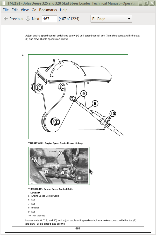
![]()