
John Deere Skid Steer Loaders 325, 328 Repair Service Manual (TM2192)
Complete service repair manual for John Deere Skid Steer Loaders 325, 328, with all the service information to maintain, repair, and rebuild like professional mechanics.
John Deere Skid Steer Loaders 325, 328 workshop service repair manual includes:
* Numbered table of contents easy to use so that you can find the information you need fast.
* Detailed sub-steps expand on repair procedure information
* Numbered instructions guide you through every repair procedure step by step.
* Notes, cautions and warnings throughout each chapter pinpoint critical information.
* Bold figure number help you quickly match illustrations with instructions.
* Detailed illustrations, drawings and photos guide you through every procedure.
* Enlarged inset helps you identify and examine parts in detail.
TM2192 - John Deere 325 and 328 Skid Steer Loader Technical Manual - Repair.PDF
TM2192 - John Deere 325 and 328 Skid Steer Loader Technical Manual - Repair.EPUB
Total Pages: 321 pages
File Format: PDF/EPUB/MOBI/AZW (PC/Mac/Android/Kindle/iPhone/iPad; bookmarked, ToC, Searchable, Printable)
Language: English
MAIN SECTIONS
Foreword
Technical Information Feedback Form
General Information
Safety
Torque Values
Wheels
Powered Wheels and Fastenings
Axles and Suspension Systems
Drive Axle Housing and Support
Axle Shaft, Bearings and Reduction Gears
Transmission
Controls Linkage
Flywheel Coupler
Hydraulic System
Engine
Removal and Installation
Engine Auxiliary Systems
Cooling System
Speed Control Group
External Fuel Supply System
Frame or Supporting Structure
Frame Installation
Operators's Station
Removal and Installation
Operator Enclosure
Seat and Seat Belt
Heating and Air Conditioning
Sheet Metal and Styling
Hood or Engine Enclosure
Loader
Attachment Coupler
Control Linkage
Frame
Hydraulic System
Dealer Fabricated Tools
tm2192 - 325 and 328 Skid Steer
Table of Contents
Foreword
Technical Information Feedback Form
Section 00: General Information
Group 0001: Safety
Recognize Safety Information
Follow Safety Instructions
Operate Only If Qualified
Wear Protective Equipment
Avoid Unauthorized Machine Modifications
Inspect Machine
Stay Clear of Moving Parts
Avoid High-Pressure Oils
Beware of Exhaust Fumes
Prevent Fires
Prevent Battery Explosions
Handle Chemical Products Safely
Dispose of Waste Properly
Prepare for Emergencies
Use Steps and Handholds Correctly
Start Only From Operator's Seat
Use and Maintain Seat Belt
Prevent Unintended Machine Movement
Avoid Work Site Hazards
Keep Riders Off Machine
Avoid Backover Accidents
Avoid Machine Tip Over
Operating or Traveling On Public Roads
Add and Operate Attachments Safely
Park And Prepare For Service Safely
Service Cooling System Safely
Remove Paint Before Welding or Heating
Make Welding Repairs Safely
Drive Metal Pins Safely
Group 0003: Torque Values
Unified Inch Bolt and Cap Screw Torque Values
Metric Bolt and Cap Screw Torque Values
Additional Metric Cap Screw Torque Values
Check Oil Lines And Fittings
Service Recommendations for O-Ring Boss Fittings
Service Recommendations for 37° Flare and 30° Cone Seat Connectors
Service Recommendations for Flared Connections—Straight or Tapered Threads
Inch Series Four Bolt Flange Fitting For High Pressure Service Recommendations
Service Recommendations For Inch Series Four Bolt Flange Fittings
O-Ring Face Seal Fittings With Metric Hex Nut And Stud End For Standard Pressure Service Recommendations
Service Recommendations for Metric Series Four Bolt Flange Fitting
Section 01: Wheels
Group 0110: Powered Wheels and Fastenings
Wheel Remove and Install (S.N. —236796)
Wheel Remove and Install (S.N. 236797— )
Section 02: Axles and Suspension Systems
Group 0201: Drive Axle Housing and Support
Axle Housing Remove and Install
Axle Housing Disassemble and Assemble
Group 0250: Axle Shaft, Bearings and Reduction Gears
Chain Case Access Plate Remove and Install
Drive Chain and Sprocket Remove and Install
Section 03: Transmission
Group 0315: Controls Linkage
Steering Dampener Remove and Install
Steering Dampener Inspection
Steering Lever Remove and Install
Steering Lever Disassemble and Assemble
Steering Cross Shaft Assembly Remove and Install
Steering Cross Shaft Disassemble and Assemble
Steering Lever Handle Remove and Install
Joystick Remove and Install—EH Controls
Group 0325: Flywheel Coupler
Hub Coupler Remove and Install
Group 0360: Hydraulic System
Hydrostatic and Hydraulic Start-Up Procedure
Hydrostatic Motor and Park Brake Remove and Install
Hydrostatic Motor and Park Brake Disassemble and Assemble
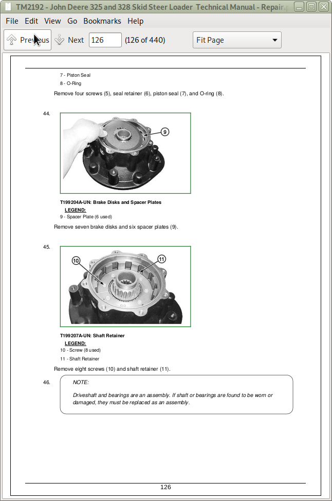
Hydrostatic Motor and Park Brake—Two Speed Disassemble and Assemble
Charge Pump Remove and Install
Charge Pump Remove and Install—EH Controls
Hydrostatic Pump Remove and Install
Hydrostatic Pump Remove and Install—EH Controls
Hydrostatic Pump Disassemble and Assemble
Hydrostatic Pump Disassemble and Assemble—EH Controls
Park Brake Solenoid Valve Manifold Remove and Install
Park Brake Solenoid Valve Remove and Install—EH Controls
Two Speed Solenoid Valve Remove and Install
Two Speed Solenoid Valve Disassemble and Assemble
Section 04: Engine
Group 0400: Removal and Installation
POWERTECH POWERTECH is a trademark of Deere & Company 2.4 L & 3.0 L (4024 & 5030) John Deere Engines
Engine Remove and Install
Alternator Remove and Install
Section 05: Engine Auxiliary Systems
Group 0510: Cooling System
Radiator Remove and Install
Fan, Fan Guard, and Fan Shroud Remove and Install
Fan Belt Remove and Install
Group 0515: Speed Control Group
Engine Speed Control Linkage Remove and Install
Engine Speed Control Linkage Remove and Install—EH Controls
Group 0560: External Fuel Supply System
Fuel Tank Remove and Install
Fuel Level Sensor Remove and Install
Auxiliary Water Separator Fuel Filter Remove and Install—If Equipped
Section 17: Frame or Supporting Structure
Group 1740: Frame Installation
Welding On Machine
Welding Repair of Major Structure
Section 18: Operators's Station
Group 1800: Removal and Installation
Cab Remove and Install
Group 1810: Operator Enclosure
Cab Door Remove and Install
Group 1821: Seat and Seat Belt
Seat Remove and Install
Seat Belt Remove and Install
Group 1830: Heating and Air Conditioning
Refrigerant Cautions and Proper Handling
Flush and Purge Air Conditioner System
R134a Refrigerant Oil Information
R134a Refrigerant Recovery/Recycling and Charging Station Installation Procedure
Recover R134a Refrigerant
Evacuate R134a System
Charge R134a System
Air Conditioner Compressor Remove and Install
Receiver-Dryer Remove and Install
Air Conditioner and Heater Remove and Install
Condenser Remove and Install
Section 19: Sheet Metal and Styling
Group 1910: Hood or Engine Enclosure
Rear Door Remove and Install
Section 31: Loader
Group 3104: Attachment Coupler
Quik-Tatch Coupler Remove and Install
Hydraulic Quik-Tatch (S.N. —131876) Cylinder Remove and Install
Hydraulic Quik-Tatch (S.N. —131876) Solenoid Valve Remove and Install
Electric Quik-Tatch (S.N. 131877— ) Cylinder Remove and Install
Group 3115: Control Linkage
Pedal Assembly Disassemble and Assemble (S.N. —150522)
Pedal Assembly Disassemble and Assemble (S.N. 150523— )
Hand Control Linkage Remove and Install (S.N. —150522)
Hand Control Linkage Remove and Install (S.N. 150523— )
Joystick Remove and Install—EH Controls
Group 3140: Frame
Upper Boom Link Remove and Install
Lower Boom Link Remove and Install
Boom Remove and Install
Boom Lock Remove and Install
Group 3160: Hydraulic System
Hydraulic Pump Remove and Install
Hydraulic Pump Remove and Install—EH Controls
Hydraulic Pump Disassemble
Hydraulic Pump Inspection
Hydraulic Pump Assemble
Hydraulic Pump Disassemble and Assemble—EH Controls
High Flow Hydraulic Pump Remove and Install
High Flow Hydraulic Pump Disassemble and Assemble
High Flow Solenoid Valve Remove and Install
High Flow Solenoid Valve Disassemble and Assemble
Control Valve Remove and Install (S.N. —150522)
Control Valve Remove and Install (S.N. 150523— )
Control Valve Remove and Install—EH Controls
Control Valve Disassemble and Assemble (S.N. —150522)
Control Valve Disassemble and Assemble (S.N. 150523— )
Control Valve Disassemble and Assemble—EH Controls
Self-Level Valve Remove and Install
Boom Lowering Valve Remove and Install
Attenuator Remove and Install
Accumulator Remove and Install
Boom Cylinder Remove and Install
Bucket Cylinder Remove and Install
Hydraulic Oil Filter Manifold Remove and Install
Hydraulic Oil Tank Remove and Install
Hydraulic Cylinder Bleed Procedure
Section 99: Dealer Fabricated Tools
Group 9900: Dealer Fabricated Tools
DFT1101 Cab and ROPS Lift Bracket
DFT1245 Engine Lifting Bracket
![]()