
John Deere Articulated Dump Trucks 350D, 400D Operation & Test Service Manual (TM1198)

Complete Diagnosis & Test manual with Electrical Wiring Diagrams for John Deere Articulated Dump Trucks 350D, 400D, with workshop information to maintain, diagnose, repair, and rebuild like professional mechanics.
John Deere Articulated Dump Trucks 350D & 400D workshop diagnostics manual includes:
* Numbered table of contents easy to use so that you can find the information you need fast.
* Detailed sub-steps expand on repair procedure information
* Numbered instructions guide you through every repair procedure step by step.
* Troubleshooting and electrical service procedures are combined with detailed wiring diagrams for ease of use.
* Notes, cautions and warnings throughout each chapter pinpoint critical information.
* Bold figure number help you quickly match illustrations with instructions.
* Detailed illustrations, drawings and photos guide you through every procedure.
* Enlarged inset helps you identify and examine parts in detail.
(SN. 608490-626762)
350D (SN. 608490-626762)
400D (SN. 608490-626762)
TM1198 - John Deere 350D, 400D Articulated Dump Truck Technical Manual - Operation & Test.PDF
TM1198 - John Deere 350D, 400D Articulated Dump Truck Technical Manual - Operation & Test.epub
Total Pages: 1,314 pages
File Format: PDF (bookmarked, ToC, Searchable, Printable, high quality)
Language: English
MAIN SECTIONS
Foreword
Technical Information Feedback Form
General Information
Safety
Diagnostic Trouble Codes (DTC)
Chassis Control Unit (CCU) Diagnostic Trouble Codes
Engine Control Unit (ECU) Diagnostic Trouble Codes
Electronic Unit Injector (EUI) Controller Diagnostic Trouble Codes
Monitor Display Unit (MDU) Diagnostic Trouble Codes
Output Expansion Unit (OEU) Diagnostic Trouble Codes
Sealed Switch Module (SSM) Diagnostic Trouble Codes
Transmission Control Unit (TCU) Diagnostic Trouble Codes
Operational Checkout Procedure
Operational Checkout Procedure
Engine
Theory of Operation
Diagnose Engine Malfunctions
Adjustments
Tests
Electrical System
System Information
System Diagrams
Sub-System Diagnostics
References
Power Train
Theory of Operation
Diagnostic Information
Tests
Pneumatic System
Theory of Operation
Diagnostic Information
Tests
Hydraulic System
Theory of Operation
Diagnostic Information
Tests
Heating and Air Conditioning
Theory of Operation
Diagnostic Information
Tests
tm1198 - 350D and 400D Articulated Dump Truck TIER 3(608490-626762)
Table of Contents
Foreword
Technical Information Feedback Form
Section 9000: General Information
Group 01: Safety
Recognize Safety Information
Follow Safety Instructions
Operate Only If Qualified
Wear Protective Equipment
Avoid Unauthorized Machine Modifications
Inspect Machine
Stay Clear of Moving Parts
Avoid High-Pressure Fluids
Avoid High-Pressure Oils
Beware of Exhaust Fumes
Prevent Fires
Prevent Battery Explosions
Handle Chemical Products Safely
Dispose of Waste Properly
Prepare for Emergencies
Use Steps and Handholds Correctly
Start Only From Operator's Seat
Use and Maintain Seat Belt
Prevent Unintended Machine Movement
Avoid Work Site Hazards
Keep Riders Off Machine
Avoid Backover Accidents
Avoid Machine Tip Over
Operating on Slopes
Operating or Traveling on Public Roads
Inspect and Maintain ROPS
Add and Operate Attachments Safely
Park and Prepare for Service Safely
Service Tires Safely
Service Cooling System Safely
Remove Paint Before Welding or Heating
Make Welding Repairs Safely
Drive Metal Pins Safely
Section 9001: Diagnostic Trouble Codes (DTC)
Group 10: Chassis Control Unit (CCU) Diagnostic Trouble Codes
Diagnostic Trouble Code (DTC) Quick Reference List—Chassis Control Unit (CCU)
000097.03 - Water In Fuel Voltage Out of Range High
000097.04 - Water In Fuel Voltage Out of Range Low
000097.16 - Water In Fuel Detected
008000.05 - Headlight Dip Open Circuit
008000.06 - Headlight Dip Short Circuit
008000.18 - Headlight Dip Less than Normal Current
008001.05 - Headlight Bright Open Circuit
008001.06 - Headlight Bright Short Circuit
008001.18 - Headlight Brights Less than Normal Current
008002.00 - System Air Pressure Voltage Too High
008002.01 - System Air Pressure Voltage Too Low
008003.00 - Start Signal Voltage Too High
008004.05 - Reverse Open Circuit
008004.06 - Reverse Short Circuit
008004.18 - Reverse Less Than Normal Current
008005.00 - Rear Two Speed Switch Voltage Too High
008006.00 - Middle Two Speed Switch
008007.05 - Rear Wiper LO Speed Open Circuit
008007.06 - Rear Wiper LO Speed Short Circuit
008007.18 - Rear Wiper Lo Speed Less Than Normal Current
008008.00 - Scraper Dash Switch Voltage Too High
008009.01 - Pressure Two Speed Switch Voltage Too High
008010.05 - Front Wiper LO Speed Open Circuit
008010.06 - Front Wiper LO Speed Short Circuit
008010.18 - Front Wiper Lo Speed Less Than Normal Current
008011.00 - Battery Voltage Too High
008011.01 - Battery Voltage Too Low
008012.00 - Horn Switch Voltage Too High
008013.05 - Park Lights Open Circuit
008013.06 - Park Lights Short Circuit
008013.18 - Park Lights Less than Normal Current
008014.01 - Ignition Supply via Fuse 25 Voltage Too Low
008015.05 - Work Lights Open Circuit
008015.06 - Work Lights Short Circuit
008015.18 - Work Lights Less than Normal Current
008016.01 - Ignition Supply via Fuse 26 Voltage Too Low
008017.01 - Brake Light Switch Voltage Too Low
008018.03 - IDL Solenoid or Bin Pressure Reduction Solenoid Voltage Too High
008018.05 - IDL Solenoid or Bin Pressure Reduction Solenoid Open Circuit or Short Circuit
008019.00 - Bonnet Fan Temp Switch Voltage Too High
008021.00 - Left Height Position Sensor Voltage Too High
008021.01 - Left Height Position Sensor Voltage Too Low
008022.01 - Hazard Dash Switch Voltage Too Low
008023.00 - Right Height Position Sensor Voltage Too High
008023.01 - Right Height Position Sensor Voltage Low
008024.03 - Bin Lever Latch or Pneumatic Blow Off Solenoid Voltage Too High
008024.05 - Bin Lever Latch or Pneumatic Blow Off Solenoid Voltage Too Low
008025.00 - Artic Angle Position Sensor Voltage Too High
008025.01 - Artic Angle Position Sensor Voltage Too Low
008026.00 - Bin Position Sensor Voltage Too High
008026.01 - Bin Position Sensor Voltage Too Low
008026.02 - Bin Position Sensor Voltage Erratic
008027.03 - CTD Solenoid or Rear Wiper High Speed Voltage Too High
008027.05 - CTD Solenoid or Rear Wiper High Speed Open Circuit or Short Circuit
008028.00 - Bin Lever Position Sensor Voltage Too High
008028.01 - Bin Lever Position Sensor Voltage Too Low
008030.01 - Park Brake Dash Switch Voltage Too Low
008031.00 - Front Two Speed Switch Voltage Too High
008032.03 - Flashing Beacon Light or Horn Voltage Too High
008032.05 - Flashing Beacon Light or Horn Open Circuit or Short Circuit
008033.00 - Aircon Evaporator Temperature Voltage Too High
008033.01 - Aircon Evaporator Temperature Voltage Too Low
008034.00 - Wet Disk Brake Temperature Voltage Too High
008034.01 - Wet Disk Brake Temperature Voltage Too Low
008035.00 - Cab Temperature Voltage Too High
008035.01 - Cab Temperature Voltage Too Low
008036.00 - 5-Volt Supply to Bin and Articulation Position Sensors Too High
008036.01 - 5-Volt Supply to Bin and Articulation Position Sensors Too High
008037.00 - 5-Volt Supply to Bin Sensors Too High
008037.01 - 5-Volt Supply to Bin Sensors Too Low
008038.01 - Ignition Power via Fuse 27 Voltage Too Low
008039.01 - Ignition Power via Fuse 28 Voltage Too Low
008040.00 - Alternator Voltage via Fuse 29 Too High
008040.01 - Alternator Voltage via Fuse 29 Too Low
008040.17 - Battery Voltage Too Low
008041.03 - Artic Reverse Light or Rear Washer Pump Voltage Too High
008041.05 - Artic Reverse Light or Rear Washer Pump Open Circuit or Short Circuit
008042.03 - Recirculation Flap or Aircon Clutch Solenoid Voltage Too High
008042.05 - Recirculation Flap or Aircon Clutch Solenoid Open Circuit or Short Circuit
008043.05 - Bin Up Solenoid Open Circuit
008043.06 - Bin Up Solenoid Short Circuit
008044.03 - Engine Running or Brake Light Output Voltage Too High
008044.05 - Engine Running or Brake Light Open Circuit or Short Circuit
008045.03 - Left Indicator Light or Right Indicator Light Voltage Too High
008045.05 - Left Indicator Light or Right Indicator Light Open Circuit
008046.03 - Front Wiper Hi Speed or Front Washer Pump Voltage Too High
008046.05 - Front Wiper Hi Speed or Front Washer Pump Open Circuit or Short Circuit
008047.03 - Mirror Heating or Hydraulic Cut Solenoid Voltage Too High
008047.05 - Mirror Heating or Hydraulic Cut Solenoid Open Circuit
008048.03 - Bin Down Solenoid Open Circuit
008048.05 - Bin Down Solenoid Short Circuit
008048.06 - Bin Down Solenoid Short to Ground
008049.03 - Overspeed Control or Park Brake Solenoid Voltage Too High
008049.05 - Overspeed Control or Park Brake Solenoid Open Circuit or Short Circuit
008050.00 - Hydraulic Temperature Sensor Voltage Too High
008050.01 - Hydraulic Temperature Sensor Voltage Too Low
008051.01 - Ignition Power Voltage via Fuse 30 Too Low
008052.01 - Ignition Power Voltage via Fuse 31 Too Low
008100.31 - Boost Pressure Protection Is Activated
008101.31 - Free Wheeling Event Detected
008102.31 - Engine is Idling for More than 20 Minutes
008103.31 - Engine RPM Exceeded Allowable Limit
008104.31 - Output Shaft Speed Exceeded Allowable Limit
008105.31 - Bin (Dump Body) Overload
008106.31 - Harsh Braking Detected
008107.31 - Engine Coolant Temperature Too High
008108.31 - Engine Oil Pressure Too Low
008109.31 - Transmission Sump Temperature Too High
008110.31 - TCU Calibration Mismatch
008111.31 - Park Brake Burnout Event Detected
008113.31 - Hydraulic Temperature Too High
008114.31 - Wet Disk Brake Temperature Too High
008116.31 - Tire Speed Limitation Exceeded
008119.31 - Unexpected Bin (Dump Body) Direction
Group 20: Engine Control Unit (ECU) Diagnostic Trouble Codes
Diagnostic Trouble Code (DTC) Quick Reference List—Engine Control Unit (ECU)
000045.03 - Constant Throttle (EVB) Open Circuit
000045.04 - Constant Throttle (EVB) Closed Circuit
000084.03 - Tachometer Signal Open Circuit
000084.04 - Tachometer Signal Short Circuit
000084.14 - Tachometer Signal Not Recognized
000098.00 - Oil Level Too High
000098.01 - Oil Level Too Low
000098.14 - Oil Level Very Low—Dangerous
000100.01 - Low Oil Pressure
000100.14 - Oil Pressure Very Low
000107.00 - Air Filter Sensor Air Pressure Too High
000107.03 - Air Filter Sensor Open Circuit
000107.04 - Air Filter Sensor Short Circuit
000110.00 - Coolant Temperature High
000110.14 - Coolant Temperature Dangerously High
000111.01 - Engine Coolant Level Low
000111.03 - Engine Coolant Level Sensor Open Circuit
000111.04 - Engine Coolant Level Sensor Short Circuit
000158.00 - Ignition Volts Too High
000158.01 - Ignition Volts Too Low
000558.05 - Pedal Switches Open
000558.12 - Pedal Switches Closed
000625.02 - CAN Error No Connection Between ECU and EUI
000625.14 - CAN Error Single Wire Connection Between ECU and EUI
000629.12 - ECU Internal Failure
000639.2 - CAN Identifiers Missing
000677.05 - Control Relay 1 Open Circuit
000677.06 - Control Relay 1 Short Circuit
000730.00 - Control Relay 2 Heat Exchanger No Increase In Intake Manifold Air Temperature
000730.01 - Control Relay 2 Heat Exchanger Contacts Sticking
000730.02 - Control Relay 2 Heat Exchanger Contacts Not Closing
000730.03 - Control Relay 2 Heat Exchanger Voltage Too High or Shorted To Battery Voltage
000730.04 - Control Relay 2 Heat Exchanger Voltage Too Low or Shorted To Ground
001004.03 - Control Relay 4 Open Circuit
001004.04 - Control Relay 4 Short Circuit
001005.03 - Pulse Width Modulation Accelerator Pedal Supply Voltage Open Circuit
001005.04 - Pulse Width Modulation Accelerator Pedal (PWM) Supply Voltage Short to Ground
001006.03 - Exhaust Brake Open Circuit
001006.04 - Exhaust Brake Short to Ground
001015.01 - Pulse Width Modulation Accelerator Pedal No Input Voltage
001015.02 - Pulse Width Modulation Accelerator Pedal (PWM) Both Signals Missing
001015.03 - Pulse Width Modulation Accelerator Pedal (PWM) Signal 2 Missing
001015.04 - Pulse Width Modulation Accelerator Pedal (PWM) Signal 1 Missing
001015.05 - Pulse Width Modulation Accelerator Pedal (PWM) Not Been Set or Programmed
001015.06 - Pulse Width Modulation Accelerator Pedal (PWM) Idle Not Been Set or Programmed
001015.07 - Pulse Width Modulation Accelerator Pedal (PWM) High Idle Not Set or Programmed
Group 30: Electronic Unit Injector (EUI) Controller Diagnostic Trouble Codes
Diagnostic Trouble Code (DTC) Quick Reference List—Electronic Unit Injector (EUI) Controller
000094.02 - Fuel Pressure Sender Value Not Recognized
000094.03 - Fuel Pressure Sender Voltage Too High or Short to Positive
000094.04 - Fuel Pressure Sender Voltage Too Low or Short to Ground
000098.02 - Engine Oil Level Incorrect or Sensor Defective
000098.03 - Engine Oil Level Sender Out of Range High
000098.04 - Engine Oil Level Sender Out of Range Low
000098.05 - Engine Oil Level Sender Open Circuit
000100.02 - Engine Oil Pressure Sender Value Not Recognized
000100.03 - Engine Oil Pressure Sensor Out of Range High
000100.04 - Engine Oil Pressure Sensor Out of Range Low
000102.01 - Charge Air Boost Path Circuit
000102.02 - Charge Air Pressure Sender Value Not Recognized
000102.03 - Intake Pressure Sensor Range Too High
000102.04 - Intake Pressure Sensor Range Too Low
000105.00 - Manifold Air Temperature Extremely High
000105.03 - Charge Air Temperature Sender Out of Range High
000105.04 - Charge Air Temperature Sender Out of Range Low
000110.03 - Coolant Temperature Sender Out of Range High
000110.04 - Coolant Temperature Sensor Range Too Low
000158.02 - Ignition Supply Not Constant between ECU and EUI
000168.03 - Input Voltage Too High
000168.04 - Input Voltage Too Low
000174.03 - Fuel Temperature Sender Out of Range High
000174.04 - Fuel Temperature Sender Out of Range Low
000175.03 - Engine Oil Temperature Sender Out of Range High
000175.04 - Engine Oil Temperature Sender Out of Range Low
000190.00 - Engine RPM Out of Range High
000609.02 - EUI Controller Internal Failure
000609.12 - EUI Controller Internal Failure
000609.14 - Internal Failure EUI Controller
000625.02 - CAN Failure
000625.14 - Controller Area Network (CAN) Failure
000636.01 - Crankshaft Sender Gap Too Small
000636.03 - Crankshaft Sender Open Circuit
000636.04 - Crankshaft Sender Short to Ground
000636.07 - Crankshaft Sender Value Not Recognized
000636.08 - Crankshaft Sender Time-Out (No Signal)
000636.14 - Crankshaft Sender Sensor Faulty or Polarized
000651.04 - Cylinder Bank #1 or #2 Short to Ground
000651.05 - Unit Pump Cylinder 1 Control Fault
000651.06 - Unit Pump Cylinder 1 Short Circuit
000651.07 - Unit Pump Cylinder 1 Impact Recognition
000651.12 - Unit Pump Cylinder 1 Automatic Running Delimitation
000651.14 - Unit Pump Cylinder 1 Single Cylinder Alignment Delimitation
000652.05 - Unit Pump Cylinder 2 Control Fault
000652.06 - Unit Pump Cylinder 2 Short Circuit
000652.07 - Unit Pump Cylinder 2 Impact Recognition
000652.12 - Unit Pump Cylinder 2 Automatic Running Delimitation
000652.14 - Unit Pump Cylinder 2 Single Cylinder Alignment Delimitation
000653.05 - Unit Pump Cylinder 3 Control Fault
000653.06 - Unit Pump Cylinder 3 Short Circuit
000653.07 - Unit Pump Cylinder 3 Impact Recognition
000653.12 - Unit Pump Cylinder 3 Automatic Running Delimitation
000653.14 - Unit Pump Cylinder 3 Injector Alignment Delimitation
000654.05 - Unit Pump Cylinder 4 Control Fault
000654.06 - Unit Pump Cylinder 4 Short Circuit
000654.07 - Unit Pump Cylinder 4 Impact Recognition
000654.12 - Unit Pump Cylinder 4 Automatic Running Delimitation
000654.14 - Unit Pump Cylinder 4 Single Cylinder Alignment Delimitation
000655.05 - Unit Pump Cylinder 5 Control Fault
000655.06 - Unit Pump Cylinder 5 Short Circuit
000655.07 - Unit Pump Cylinder 5 Impact Recognition
000655.12 - Unit Pump Cylinder 5 Automatic Running Delimitation
000655.14 - Unit Pump Cylinder 5 Single Cylinder Alignment Delimitation
000656.05 - Unit Pump Cylinder 6 Control Fault
000656.06 - Unit Pump Cylinder 6 Short Circuit
000656.07 - Unit Pump Cylinder 6 Impact Recognition
000656.12 - Unit Pump Cylinder 6 Automatic Running Delimitation
000656.14 - Unit Pump Cylinder 6 Single Cylinder Alignment Delimitation
000657.05 - Unit Pump Cylinder 7 Control Fault
000657.06 - Unit Pump Cylinder 7 Short Circuit
000657.07 - Unit Pump Cylinder 7 Impact Recognition
000657.12 - Unit Pump Cylinder 7 Automatic Running Delimitation
000657.14 - Unit Pump Cylinder 7 Single Cylinder Alignment Delimitation
000658.05 - Unit Pump Cylinder 8 Control Fault
000658.06 - Unit Pump Cylinder 8 Short Circuit
000658.07 - Unit Pump Cylinder 8 Impact Recognition
000658.12 - Unit Pump Cylinder 8 Automatic Running Delimitation
000658.14 - Unit Pump Cylinder 8 Single Cylinder Alignment Delimitation
000677.03 - Starter Relay Externally Engaged
000677.05 - Starter Relay Open Circuit
000677.06 - Starter Relay Short to Ground
000677.07 - Starter Relay Starter Not Engaging
000677.14 - Starter Relay Sticking
000697.03 - PWM Driver 1: Proportional Valve 1: Exhaust Brake Control: Short to Positive
000697.04 - Proportional Valve Bank 1 Short Circuit
000697.05 - PWM Driver 1: Proportional Valve 1: Exhaust Brake Control: Open Circuit
000697.06 - PWM Driver 1: Proportional Valve 1: Exhaust Brake Control: High Side Line Short to Ground
000698.03 - PWM Driver 2: Proportional Valve 2: Exhaust Brake Control: Constant Throttle Valve High Side Line Short to Positive
000698.05 - PWM Driver 2: Proportional Valve 2: Exhaust Brake Control: Constant Throttle Valve Low Side Line Short to Ground or Open Circuit
000698.06 - PWM Driver 2: Proportional Valve 2: Exhaust Brake Control: Constant Throttle Valve High Side Line Short to Ground
000699.03 - PWM Driver 3: Proportional Valve 3: Control Blower 1: Short to Positive
000699.05 - PWM Driver 3: Proportional Valve 3: Control Blower 1: Open Circuit
000699.06 - PWM Driver 3: Proportional Valve 3: Control Blower 1: High Side Line Short to Ground
000700.03 - PWM Driver 4: Proportional Valve 4: Control Blower 2: Short to Positive
000700.05 - PWM Driver 4: Proportional Valve 4: Control Blower 2: Open Circuit
000700.06 - PWM Driver 4: Proportional Valve 4: Control Blower 2: High Side Line Short to Ground
000723.03 - Camshaft Sender Open Circuit
000723.04 - Camshaft Sender Short to Ground
000723.08 - Camshaft Sender Time-Out (No Signal)
000723.14 - Camshaft Sender Sensor Faulty or Polarized
000986.08 - Blower Speed Time-Out (No Signal)
Group 40: Monitor Display Unit (MDU) Diagnostic Trouble Codes
Diagnostic Trouble Code (DTC) Quick Reference List—Monitor Display Unit (MDU)
000237.13 - VIN Mismatch between MDU and CCU
000628.13 - MDU Controller is in Bootmode
000630.13 - EOL Not Programmed Correctly
000639.19 - Loss of All CAN Messages
000830.00 - Fuel Sensor Above Normal
000830.01 - Fuel Sensor Below Normal
002000.19 - Loss of ECU CAN Messages
002003.19 - Loss of TCU CAN Messages
002033.09 - No CAN Messages
002033.19 - Loss of CCU CAN Messages
002049.19 - Loss of OEU CAN Messages
002064.19 - Loss of OBW Can Messages
002140.19 - Loss of SSM CAN Messages
002251.19 - Loss of MMU CAN Messages
007000.31 - Supply Voltage Direction
008110.31 - Allison TCU Calibration Mismatch
Group 50: Output Expansion Unit (OEU) Diagnostic Trouble Codes
Diagnostic Trouble Code (DTC) Quick Reference List—Output Expansion Unit (OEU)
009001.05 - Blower Speed 3 Open Circuit
009001.06 - Blower Speed 3 Short Circuit
009001.18 - Blower High Speed Less Than Normal Current
009002.05 - Blower Speed 2 Open Circuit
009002.06 - Blower Speed 2 Short Circuit
009002.18 - Blower Medium Speed Less Than Normal Current
009004.05 - Blower Speed 1 Open Circuit
009004.06 - Blower Speed 1 Short Circuit
009004.18 - Blower Speed 1 Less Than Normal Current
009005.05 - Bonnet Fan 2 Open Circuit
009005.06 - Bonnet Fan 2 Short Circuit
009005.18 - Bonnet Fan 2 Less Than Normal Current
009006.01 - Ignition Supply Voltage via Fuse 18 Too Low
009007.05 - Starter Open Circuit
009007.06 - Starter Short to Ground
009007.18 - Starter Less Than Normal Current
009008.01 - Ignition Supply Voltage via Fuse 19 Too Low
009009.03 - Gear Hold Voltage Too High
009009.05 - Gear Hold Open Circuit or Short Circuit
009010.03 - Green or Yellow Load Light Short to Power
009010.05 - Green or Yellow Load Light Open Circuit
009011.03 - Automatic Neutral or Pre-Select 2nd Gear Voltage Too High
009011.05 - Automatic Neutral or Pre-Select 2nd Gear Open Circuit or Short Circuit
009012.05 - Load Light Red or Laden-Unladen Open Circuit or Short Circuit
009013.01 - Ignition Power Voltage via Fuse 20 Too Low
009014.01 - Ignition Power Voltage via Fuse 21 Too Low
009015.00 - Alternator Voltage Via Fuse 22 Too High
009015.01 - Alternator Voltage Via Fuse 22 Too Low
009016.03 - Fan Medium Solenoid or Fan Low Solenoid Voltage Too High
009016.05 - Fan Medium Solenoid or Fan Low Solenoid Open Circuit or Short Circuit
009017.03 - Heater Valve Voltage Too High
009017.05 - Heater Valve Open Circuit or Short Circuit
009018.05 - Engine Cooling Fan Open Circuit
009018.06 - Engine Cooling Fan Short to Ground
009019.03 - Fan Cut Solenoid Voltage Too High
009019.05 - Fan Cut Solenoid Open Circuit or Short Circuit
009021.03 - Left Strut Up/Down Solenoid Short to Power
009021.05 - Left Strut Up/Down Solenoid Open Circuit
009022.03 - Middle-Demist Actuator or Feet Actuator Voltage Too High
009022.05 - Middle-Demist Actuator or Feet Actuator Open Circuit or Short Circuit
009024.03 - Right Strut Up/Down Solenoid Voltage High
009024.05 - Right Strut Up/Down Solenoid Current Low
009025.01 - Ignition Power Voltage via Fuse 23 Too Low
009026.01 - Ignition Power Voltage via Fuse 24 Too Low
Group 60: Sealed Switch Module (SSM) Diagnostic Trouble Codes
Diagnostic Trouble Code (DTC) Quick Reference List—Sealed Switch Module (SSM)
000629.12 - Sealed Switch Module Watchdog Time-Out
000639.09 - Sealed Switch Module No CAN Message
000639.12 - Sealed Switch Module CAN Lost Message
000639.13 - Sealed Switch Module CAN Warning Limit Exceeded
000639.19 - Sealed Switch Module CAN Bus Off
523523.10 - Front Wiper Switch Stuck
523524.10 - Retarder Increase Switch Stuck
523525.10 - Retarder Decrease Switch Stuck
523526.10 - Headlight Switch Stuck
523527.10 - Rotating Beacon Light Switch Stuck
523528.10 - Bin Maximum Position Switch Stuck
523529.10 - Temperature Control Decrease Switch Stuck
523530.10 - Temperature Control Increase Switch Stuck
523531.10 - Air Flow Control Switch Stuck
523532.10 - Two-Speed Switch Stuck
523533.10 - Range Hold Switch Stuck
523534.10 - Inter-Axle Lock Switch Stuck
523535.10 - Differential Lock Switch Stuck
523536.10 - Blower Motor Speed Control Switch Stuck
523537.10 - Air Recirculation Switch Stuck
523538.10 - Air Conditioning On/Off Switch Stuck
523607.10 - Bin Production Switch Stuck
523608.10 - Mirror Defroster Switch Stuck
523609.10 - Work Light Switch Stuck
523610.10 - Rear Wiper Switch Stuck
Group 70: Transmission Control Unit (TCU) Diagnostic Trouble Codes
Diagnostic Trouble Code (DTC) Quick Reference List—Transmission Control Unit (TCU)
2003.31 - TCU Error Code
C1312 - Retarder Request Sensor Failed Low
C1313 - Retarder Request Sensor Failed High
P0122 - Pedal Position Sensor Circuit Low Voltage
P0123 - Pedal Position Sensor Circuit High Voltage
P0218 - Transmission Fluid Overtemperature
P0561 - System Voltage Performance
P0562 - System Voltage Low
P0563 - System Voltage High
P0602 - TCU Not Programmed
P0610 - TCU Vehicle Options Error (Trans ID)
P0613 - TCU Processor
P0614 - Torque Control Mismatch (ECU/TCU)
P0634 - TCU Internal Temperature Too High
P063E - Auto Configuration Throttle Input Not Present
P063F - Auto Configuration Engine Coolant Temp Input Not Present
P0658 - Actuator Supply Voltage 1 Low (HSD 1 Open/Gnd)
P0659 - Actuator Supply Voltage 1 High (HSD 1 batt)
P0702 - Transmission Control System Electrical (Trans ID)
P0703 - Brake Switch Circuit
P0708 - Transmission Range Sensor Circuit High Input
P070C - Transmission Fluid Level Sensor Circuit Low Input
P070D - Transmission Fluid Level Sensor Circuit High Input
P0711 - Transmission Fluid Temperature Sensor Circuit Performance
P0712 - Transmission Fluid Temperature Sensor Circuit Low Input
P0713 - Transmission Fluid Temperature Sensor Circuit High Input
P0716 - Turbine Speed Sensor Circuit Performance
P0717 - Turbine Speed Sensor Circuit No Signal (Rapid Decel)
P071A - Transmission Mode Switch "A" Circuit
P071D - Transmission Mode Switch "B" Circuit
P0721 - Output Speed Sensor Circuit Performance
P0722 - Output Speed Sensor Circuit No Signal (rapid decel)
P0726 - Engine Speed Input Circuit Performance
P0727 - Engine Speed Input Circuit No Signal (rapid decel)
P0729 - Incorrect 6th Gear Ratio
P0731 - Incorrect 1st Gear Ratio
P0732 - Incorrect 2nd Gear Ratio
P0733 - Incorrect 3rd Gear Ratio
P0734 - Incorrect 4th Gear Ratio
P0735 - Incorrect 5th Gear Ratio
P0736 - Incorrect Reverse Ratio
P0741 - Torque Converter Clutch System Stuck Off
P0776 - PCS 2 Controlled Clutch Stuck Off
P0777 - PCS 2 Controlled Clutch Stuck On
P0796 - PCS 3 Controlled Clutch Stuck Off
P0797 - PCS 3 Controlled Clutch Stuck On
P0842 - Transmission Pressure Switch 1 Circuit Low
P0843 - Transmission Pressure Switch 1 Circuit High
P0880 - TCU Power Input Signal
P0881 - TCU Power Input Signal Performance
P0882 - TCU Power Input Signal Low
P0883 - TCU Power Input Signal High
P0894 - Transmission Component Slipping
P0960 - Pressure Control Solenoid (PCS) MM Control Circuit Open
P0962 - Pressure Control Solenoid (PCS) MM Control Circuit Low
P0963 - Pressure Control Solenoid (PCS) MM Control Circuit High
P0964 - Pressure Control Solenoid (PCS) 2 System Open
P0966 - Pressure Control Solenoid (PCS) 2 Control Circuit Low
P0967 - Pressure Control Solenoid (PCS) 2 Control Circuit High
P0968 - Pressure Control Solenoid (PCS) 3 System Open
P0970 - Pressure Control Solenoid (PCS) 3 Control Circuit Low
P0971 - Pressure Control Solenoid (PCS) 3 Control Circuit High
P0973 - Shift Solenoid (SS) 1 Control Circuit Low
P0974 - Shift Solenoid (SS) 1 Control Circuit High
P0975 - Shift Solenoid (SS) 2 Control Circuit Open
P0976 - Shift Solenoid (SS) 2 Control Circuit Low
P0977 - Shift Solenoid (SS) 2 Control Circuit High
P0989 - Retarder Pressure Sensor Failed Low
P0990 - Retarder Pressure Sensor Failed High
P1739 - Incorrect Low Gear Ratio
P1891 - Throttle Position Sensor PWM Signal Low Input
P1892 - Throttle Position Sensor PWM Signal High Input
P2184 - Engine Coolant Temperature Sensor 2 Circuit Low
P2185 - Engine Coolant Temperature Sensor 2 Circuit High
P2637 - Torque Management Feedback Signal "A"
P2641 - Torque Management Feedback Signal "B"
P2670 - Actuator Supply Voltage 2 Low (HSD 2 gnd)
P2671 - Actuator Supply Voltage 2 High (HSD 2 batt/open)
P2685 - Actuator Supply Voltage 3 Low (HSD 3 gnd)
P2686 - Actuator Supply Voltage 3 High (HSD 3 batt/open)
P2714 - PCS 4 Controlled Clutch Stuck Off
P2715 - PCS 4 Controlled Clutch Stuck On
P2718 - Pressure Control Solenoid (PCS) 4 System Open
P2720 - Pressure Control Solenoid (PCS) 4 Control Circuit Low
P2721 - Pressure Control Solenoid (PCS) 4 Control Circuit High
P2723 - PCS 1 Controlled Clutch Stuck Off
P2724 - PCS 1 Controlled Clutch Stuck On
P2727 - Pressure Control Solenoid (PCS) 1 System Open
P2729 - Pressure Control Solenoid (PCS) 1 Control Circuit Low
P2730 - Pressure Control Solenoid (PCS) 1 Control Circuit High
P2736 - Pressure Control Solenoid (PCS) 5 System Open
P2738 - Pressure Control Solenoid (PCS) 5 Control Circuit Low
P2739 - Pressure Control Solenoid (PCS) 5 Control Circuit High
P2740 - Retarder Oil Temperature Hot
P2742 - Retarder Oil Temperature Sensor Circuit Low Input
P2743 - Retarder Oil Temperature Sensor Circuit High Input
P2761 - TCC PCS Control Circuit Open
P2763 - TCC PCS Control Circuit High
P2764 - TCC PCS Control Circuit Low
P278A - Kickdown Input Switch Circuit
P2793 - Gear Shift Direction Circuit
P2808 - PCS 6 Controlled Clutch Stuck Off
P2809 - PCS 6 Controlled Clutch Stuck On
P2812 - Pressure Control Solenoid (PCS) 6 System Open
P2814 - Pressure Control Solenoid (PCS) 6 Control Circuit Low
P2815 - Pressure Control Solenoid (PCS) 6 Control Circuit High
U0001 - High Speed CAN Communication Bus
U0010 - Medium Speed CAN Communication Bus
U0100 - Lost Communication with ECU “A”
U0103 - Gear Shift Module 1 State of Health
U0115 - Lost Communication with ECU CAN
U0291 - Gear Shift Module 2 State of Health
U0304 - Software Incompatibility with Gear Shift Control Module 1
U0333 - Software Incompatibility with Gear Shift Control Module 2
U0404 - Gear Shift Module 1 Invalid Data
U0592 - Gear Shift Module 2 Invalid Data
Section 9005: Operational Checkout Procedure
Group 10: Operational Checkout Procedure
Operational Checkout
Section 9010: Engine
Group 05: Theory of Operation
350D and 400D (OM 501) Engine Sectional View
Engine Operation
Electronic Unit Injector Fuel System
Fuel Delivery
Cold Start Operation
Group 15: Diagnose Engine Malfunctions
Diagnose Engine Malfunctions
Group 20: Adjustments
Display Monitor Tachometer
Slow and Fast Idle Adjustment
Valve Clearance Adjustment
Exhaust Brake Adjustment
Group 25: Tests
Cylinder Compression Test
Fuel Pump Pressure Test
Oil Pump Pressure Test
Engine Boost Pressure Test
Section 9015: Electrical System
Group 05: System Information
Electrical Diagram Information
Explanation of Wire Markings
Component Identification Table
Fuse (Blade-Type) Color Codes
Group 10: System Diagrams
Fuse Specifications
System Functional Schematic, Wiring Diagrams, and Component Locations Master Legend
System Functional Schematic and Section Legend
JDLink™ System Functional Schematic—MIG/GTT
JDLink™ System Functional Schematic—MTG/SAT
Main Power Harness (W6) Component Location
Main Power Harness (W6) Wiring Diagram
Front Frame/Engine Harness (W7) Component Location
Front Frame/Engine Harness (W7) Wiring Diagram
Engine Main Harness (W8) Component Location
Engine Main Harness (W8) Wiring Diagram
Cab Main Harness (W10) Component Location
Cab Main Harness (W10) Wiring Diagram
Transmission Control Harness (W12) Component Location
Transmission Control Harness (W12) Wiring Diagram
Transmission Harness (W13) Component Location
Transmission Harness (W13) Wiring Diagram
Hydraulic Harness (W14) Component Location
Hydraulic Harness (W14) Wiring Diagram
Rear Frame Harness (W15) and Artic Harness (W19) Component Location
Rear Frame Harness (W15) and Artic Harness (W19) Wiring Diagrams
Work Light Harness (W16) Component Location
Work Light Harness (W16) Wiring Diagram
Air Conditioner Actuator Harness (W18) Component Location
Air Conditioning Actuator Harness (W18) Wiring Diagram
AM/FM Radio Harness (W20) Component Location
AM/FM Radio Harness (W20) Wiring Diagram
JDLink™ System Harnesses Component Location—MIG/GTT
JDLink™ System Harnesses Component Location—MTG/SAT
JDLink™ System Wiring Diagram—MIG/GTT
JDLink™ Power Harness (W26) Wiring Diagram (S.N. 617193— )
JDLink™ Power Extension Harness (W27) Wiring Diagram (S.N. 617193—XXXXXX)
JDLink™ System Wiring Diagrams—MTG/SAT
Number Plate Light Harness (W30) Wiring Diagram—If Equipped
Seat Heater Harness (W33) Component Location—If Equipped
Seat Heater Harness (W33) Wiring Diagram—If Equipped
Pneumatic Vertical Valve Stack Harness (W40) Component Location (If Equipped)
Pneumatic Vertical Valve Stack Harness (W40) Wiring Diagram (If Equipped)
Group 15: Sub-System Diagnostics
Starting and Charging Circuit Theory of Operation
Cold Start Circuit Theory of Operation
Electronic Unit Injector Controller Circuit Theory of Operation
Engine Control Unit Circuit Theory of Operation
Transmission Control Unit and Retarder Circuit Theory of Operation
Chassis Control Unit Circuit Theory of Operation
Output Expansion Unit Circuit Theory of Operation
Bin Control and Range Hold Circuit Theory of Operation
Fan Control Circuit Theory of Operation
Differential Lock and Inter-Axle Lock Circuit Theory of Operation
Park Brake Circuit Theory of Operation
Monitor Display Unit Circuit Theory of Operation
Turn Lights and 4-Way Flasher Circuit Theory of Operation
Service Brake Light Circuit Theory of Operation
Backup Alarm and Backup Light Circuit Theory of Operation
Wiper and Washer Circuit Theory of Operation
Battery Balancer and 12-Volt Accessory Circuit Theory of Operation (608490—617192)
Voltage Converter Theory of Operation (S.N. 617193— )
Air Conditioning Circuit Theory of Operation
Electric Mirror Circuit Theory of Operation
Unloader Valve Heater Circuit Theory of Operation
Group 20: References
Electrical Component Specifications
Sealed Switch Module (SSM) Test
Monitor Display Unit (MDU)—Service Mode
Diagnostic Trouble Codes—After Machine Repair
Diagnostic Trouble Codes—How Codes Are Displayed On Monitor Display Unit
Diagnostic Trouble Codes—How to Use Listing for Transmission Codes
Intermittent Diagnostic Trouble Code (DTC) Diagnostics
SERVICE ADVISOR Diagnostic Application
Service ADVISOR™ Connection Procedure
Reading Diagnostic Trouble Codes with SERVICE ADVISOR Diagnostic Application
JDLink™ System Identification
JDLink™ Connection Procedure—If Equipped
Allison DOC Connection Procedure
Mercedes Minidiag2 Connection Procedure
Key Switch Test
Relay Test
Diode Test
Alternator Test
CAN Circuit Testing
Pneumatic System Solenoids, Pressure Switches, and Sensor Tests
Hydraulic Pressure Switches Test
Hydraulic Temperature Sensors Test
Bin Position Sensor Test
Bin Sensor Calibration
Steering Column Switch Test
Transmission Speed Sensors Test
Transmission Solenoids Test
Cold Start Operational Testing
Cold Start Glow Plug Test
Cold Start Temperature Sensor Test
Electronic Unit Injector Controller Remove and Install
Engine Control Unit Remove and Install
Cold Start Module Remove and Install
Chassis Control Unit Remove and Install
Output Expansion Unit Remove and Install
Transmission Control Unit Remove and Install
Battery Balancer Remove and Install
Program Monitor Display Unit (MDU)
Monitor Display Unit Remove and Install
Accelerator Pedal Position Sensor Remove, Install, and Calibrate
Replace DEUTSCH DEUTSCH is a trademark of Deutsch Co. Rectangular or Triangular Connectors
Replace DEUTSCH DEUTSCH is a trademark of the Deutsch Co. Connectors
Install DEUTSCH DEUTSCH is a trademark of the Deutsch Co. Contact
Replace WEATHER PACK WEATHER PACK is a trademark of Packard Electric. Connector
Install WEATHER PACK WEATHER PACK is a trademark of Packard Electric. Contact
Replace (Pull Type) METRI-PACK Connectors
Connector Terminal Test
Replace (Push Type) METRI-PACK Connectors
Remove Connector Body from Blade Terminals
Section 9020: Power Train
Group 05: Theory of Operation
Transmission External Components
Transmission Control System
Transmission Cross Sectional Diagram
Torque Converter Operation
Transmission Clutch Engagement
Transmission Retarder Operation
Transmission Oil Temperature Sensor Operation
Differential Lock Operation
Transfer Case and Inter-Axle Differential Lock (IDL) Operation
Service Brake System Operation
Group 15: Diagnostic Information
Diagnostic Procedure
Diagnose Service Brake System Malfunctions
Diagnose Power Train System Malfunctions
Power Train Component Location Diagram
Group 25: Tests
Transmission Warm-Up Procedure
Transmission Pressure Test
Transmission Clutch Drag Test
Torque Converter Stall Test—350D
Torque Converter Stall Test—400D
Torque Converter Stator Tests
Torque Converter Lockup Test
Clutch Enable Test
Adaptive Shift Parameters Reset
Fast Adaptive Reset
Transmission Oil Cooler Restriction Test
Front Suspension Strut Leakage Check
Front Axle Suspension Strut Height Check
Park Brake Test
Park Brake Pad Thickness Check
Park Brake Adjustment
Wheel Hub Bearing Preload Adjustment (Wheel Installed)
Checking Controlled Traction Clutch (Differential Lock) Condition
Accumulator Pressure Reducing Valve Test and Adjustment
Front and Rear Service Brake Accumulators Pressure Test and Charge Procedure
Service Brake Accumulator Charge Valve Test and Adjustment
Service Brake Low Pressure Switch and Service Brake Accumulator Charge Test
Service Brake Valve Test
Service Brake (Wet Disk) Thermal Valve Test
Service Brake (Wet Disk) Cooling System Bypass Check Valve Test
Service Brake (Wet Disk) Cooler Restriction Test
Service Brake (Wet Disk) Cooling Oil Filter Restriction Test
Section 9022: Pneumatic System
Group 05: Theory of Operation
Pneumatic System Schematic
Pneumatic System Schematic With Vertical Valve Stack (If Equipped)
Pneumatic System Operation
Air Pressure Supply Circuit Operation
Air Dryer and Unloader Valve
Pneumatic Manifold Component Location
Pneumatic Circuit
Group 15: Diagnostic Information
Diagnostic Procedure
Diagnose Pneumatic System Malfunctions
Pneumatic System Component Location Diagram
Group 25: Tests
Pneumatic System Main Pressure Test and Adjustment
Park Brake Pressure Test
Section 9025: Hydraulic System
Group 05: Theory of Operation
Articulated Dump Truck Hydraulic System Operation
Main Hydraulic Pump Operation
Main Hydraulic Pump Load Sense Operation
Check Valve Manifold Theory of Operation
Service Brake System Operation
Steering and Secondary Steering System Operation
Steering Valve Operation
Secondary Steering Pump Operation
Hydraulic System Manifold Operation
Fan Drive System Operation
Bin Control Valve Operation
Hydraulic System Circuit Symbols
Hydraulic System Schematic—Caliper Brakes
Hydraulic System Schematic—Wet Disk Brakes
Group 15: Diagnostic Information
Diagnostic Procedure
Diagnose Hydraulic System Malfunctions
Diagnose Service Brake System Malfunctions
Diagnose Steering System Malfunctions
Hydraulic System Component Location
Group 25: Tests
JT02156A Digital Pressure/Temperature Analyzer Installation
Hydraulic Oil Cleanup Procedure
Hydraulic System Warm-Up Procedure
Cycle Time Test
Main Hydraulic Pump Residual and Compensator Valves Test and Adjustment
System Relief Valve and Bin Raise Circuit Relief Valve Test
Priority Valve Test
Steering Relief Valve Pressure Test and Adjustment
Steering Cylinder Leakage Test
Secondary Steering Pump Residual and Compensator Valves Test and Adjustment
Bin Raise Pressure Limiting Valve Test and Adjustment
Bin Lower Circuit Relief Valve Test
Fan Drive Control Valve Test and Adjustment
Accumulator Pressure Reducing Valve Test and Adjustment
Front and Rear Service Brake Accumulators Pressure Test and Charge Procedure
Service Brake Accumulator Charge Valve Test and Adjustment
Service Brake Low Pressure Switch and Service Brake Accumulator Charge Test
Service Brake Valve Test
Service Brake (Wet Disk) Thermal Valve Test
Service Brake (Wet Disk) Cooling System Bypass Check Valve Test
Service Brake (Wet Disk) Cooler Restriction Test
Service Brake (Wet Disk) Cooling Oil Filter Restriction Test
Section 9031: Heating and Air Conditioning
Group 05: Theory of Operation
Air Conditioning System Cycle of Operation
Heater Core Operation
Group 15: Diagnostic Information
Diagnose Air Conditioning System Malfunctions
Diagnose Heater System Malfunctions
Heating/Air Conditioning Component Location
Group 25: Tests
Air Conditioning Operational Checks
R134a Air Conditioning System Test
Operating Pressure Diagnostic Chart
A/C Freeze Control Switch Test
A/C Compressor Clutch Test
A/C High/Low Pressure Switch Test
A/C Expansion Valve Test
Blower Motor Resistor/Thermofuse Test
Expansion Valve Bench Test
Refrigerant Leak Test
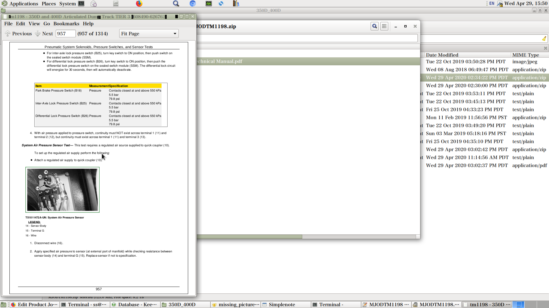
![]()