
John Deere Articulated Dump Trucks 370E, 410E, 460E Operation and Test Service Manual (TM12406)

Complete Diagnosis and Test manual with electrical wiring diagrams for John Deere Articulated Dump Trucks 370E, 410E, 460E (iT4/S3B), with all the shop information to maintain, diagnose, and service like professional mechanics.
John Deere Articulated Dump Trucks (ADT) 370E, 410E, 460E workshop Operation and Test manual includes:
* Numbered table of contents easy to use so that you can find the information you need fast.
* Detailed sub-steps expand on repair procedure information
* Numbered instructions guide you through every repair procedure step by step.
* Troubleshooting and electrical service procedures are combined with detailed wiring diagrams for ease of use.
* Notes, cautions and warnings throughout each chapter pinpoint critical information.
* Bold figure number help you quickly match illustrations with instructions.
* Detailed illustrations, drawings and photos guide you through every procedure.
* Enlarged inset helps you identify and examine parts in detail.
TM12406 - John Deere 370E, 410E, 460E Articulated Dump Truck Technical Manual - Operation and Test.PDF
TM12406 - John Deere 370E, 410E, 460E Articulated Dump Truck Technical Manual - Operation and Test.EPUB
Total Pages: 2,510 pages
File Format: PDF/EPUB/MOBI/AZW (PC/Mac/Android/Kindle/iPhone/iPad; bookmarked, ToC, Searchable, Printable)
Language: English
(SN. E634583-668586)
370E (PIN: 1DW370E***C634583-668586)
410E (PIN: 1DW410E***C634583-668586)
460E (PIN: 1DW460E***C634583-668586)
MAIN SECTIONS
Foreword
Manual Identification-READ THIS FIRST!
General Information
Safety
Diagnostics
Transmission Control Unit (TCU) Diagnostic Trouble Codes
Engine Control Unit (ECU) Diagnostic Trouble Codes
Chassis Control Unit (CCU) Diagnostic Trouble Codes
CAN Monitor Unit (CMU) Diagnostic Trouble Codes
25-Button Sealed Switch Module SSM (OC3) Diagnostic Trouble Codes
15-Button Sealed Switch Module SSM (OC4) Diagnostic Trouble Codes
Operational Checkout Procedure
Operational Checkout Procedure
Engine
Theory of Operation
Diagnostic Information
Adjustments
Tests
Electrical System
System Information
System Diagrams
Sub-System Diagnostics
Monitor Operation
References
Power Train
Theory of Operation
Diagnostic Information
Tests
Hydraulic System
Theory of Operation
Diagnostic Information
Test
Heating and Air Conditioning
Theory of Operation
Diagnostic Information
Tests
tm12406 - 370E, 410E, and 460E Articulated Dump Truck
Table of Contents
Foreword
Manual Identification—READ THIS FIRST!
Section 9000: General Information
Group 01: Safety
Safety and Operator Convenience Features
Recognize Safety Information
Follow Safety Instructions
Operate Only If Qualified
Wear Protective Equipment
Avoid Unauthorized Machine Modifications
Inspect Machine
Stay Clear of Moving Parts
Avoid High-Pressure Fluids
Avoid High-Pressure Oils
Work In Ventilated Area
Prevent Fires
Prevent Battery Explosions
Handle Chemical Products Safely
Decommissioning — Proper Recycling and Disposal of Fluids and Components
Exhaust Filter Ash Handling and Disposal
Prepare for Emergencies
Clean Debris from Machine
Use Steps and Handholds Correctly
Start Only From Operator's Seat
Use and Maintain Seat Belt
Prevent Unintended Machine Movement
Avoid Work Site Hazards
Keep Riders Off Machine
Avoid Backover Accidents
Avoid Machine Tip Over
Operating on Slopes
Operating or Traveling On Public Roads
Inspect and Maintain ROPS
Add and Operate Attachments Safely
Park and Prepare for Service Safely
Service Cooling System Safely
Remove Paint Before Welding or Heating
Make Welding Repairs Safely
Drive Metal Pins Safely
Service Tires Safely
Clean Exhaust Filter Safely
Section 9001: Diagnostics
Group 10: Transmission Control Unit (TCU) Diagnostic Trouble Codes
523000.01 - Battery Low Undervoltage
523000.03 - Battery Overvoltage
523000.04 - Battery Undervoltage
523001.01 - Battery Undervoltage During Engine Start
523010.03 - EC-II Internal 5V Power Supply Overvoltage
523010.04 - EC-II Internal 5V Power Supply Undervoltage
523011.04 - EC-II Internal 7V Power Supply Undervoltage
523020.03 - Speed Sensor Supply Overvoltage
523020.04 - Speed Sensor Supply Undervoltage
523020.06 - Speed Sensor Voltage Low
523021.03 - Temp/Oil Filt Supply Overvoltage
523021.04 - Temp/Oil Filt Supply Undervoltage
523021.06 - Temp/Oil Filt Supply Voltage Low
523022.03 - Supply 1 For Sensors Overvoltage
523022.04 - Supply 1 For Sensors Undervoltage
523022.06 - Supply 1 For Sensors Short to Ground
523030.03 - Propvalve Supply 1 Overvoltage
523030.04 - Propvalve Supply 1 Undervoltage
523030.06 - VPS1 Power Supply Voltage Low
523031.03 - Propvalve Supply 2 Overvoltage
523031.04 - Propvalve Supply 2 Undervoltage
523031.06 - VPS2 Power Supply Voltage Low
523040.00 - TCU Overtemp
523040.02 - TCU Temp Invalid
523045.12 - Internal Error 1
523046.12 - Internal Error 2
523047.12 - Internal Error 3
523048.12 - Internal Error 4
523049.12 - Unknown TCU Hardware Detected
523100.02 - Turbine Speed Unknown Input
523100.03 - Turbine Speed Sensor Input Overvoltage
523100.06 - Turbine Speed Sensor Voltage Low
523100.07 - Turbine Speed Input Speed Mismatch
523100.08 - Turbine Speed Error ROT DIR Unknown
523100.09 - Turbine Speed Error Speed Unknown
523100.11 - Turbine Speed Error ROT DIR Mismatch
523105.02 - Speed Sensor 1 Unknown Input
523105.03 - Speed Sensor 1 Overvoltage
523105.06 - Speed Sensor 1 Voltage Low
523105.07 - Speed Sensor 1 Speed Mismatch
523105.08 - Speed Sensor 1 DIR ROT Unknown
523105.09 - Speed Sensor 1 Speed Unknown
523105.11 - Speed Sensor 1 DIR ROT Mismatch
523110.02 - Speed Sensor 2 Unknown Input
523110.03 - Speed Sensor 2 Overvoltage
523110.06 - Speed Sensor 2 Voltage Low
523110.07 - Speed Sensor 2 Speed Mismatch
523110.08 - Speed Sensor 2 DIR ROT Unknown
523110.09 - Speed Sensor 2 Speed Unknown
523110.11 - Speed Sensor 2 DIR ROT Mismatch
523115.02 - Output Speed Sensor Unknown Input
523115.03 - Output Speed Sensor Overvoltage
523115.06 - Output Speed Sensor Voltage Low
523115.07 - Output Speed Sensor Speed Mismatch
523115.08 - Output Speed Sensor DIR ROT Unknown
523115.09 - Output Speed Sensor Speed Unknown
523115.11 - Output Speed Sensor DIR ROT Mismatch
523120.02 - Unknown Electrical Component at Speed Sensor Input 5
523120.03 - Speed Sensor Input 5 Overvoltage
523120.06 - Speed Sensor Input 5 Open or Short to Ground
523125.02 - Unknown Electrical Component at Voltage Input 1
523130.02 - Unknown Electrical Component at Voltage Input 2
523140.02 - Sump Temp Input Unknown Input
523140.03 - Sump Temp Sensor Voltage High
523140.05 - Sump Temp Sensor Overvoltage
523140.06 - Sump Temp Sensor Voltage Low
523145.02 - Torq/RTDR Temp Snsr Unknown Input
523145.03 - Torq/RTDR Temp Snsr Unknown Voltage High
523145.05 - Torq/RTDR Temp Snsr Overvoltage
523145.06 - Torq/RTDR Temp Snsr Ground Low
523150.02 - Unknown Electrical Component at Current Input 1
523155.02 - Unknown Electrical Component at Current Input 2
523155.03 - Oil Filt Rest Switch Overvoltage
523155.04 - Oil Filt Rest Switch Undervoltage
523155.06 - Oil Filt Rest Switch Voltage Low
523200.00 - Clutch A Slip Unintentional Slip
523200.02 - Current Output 1 Unknown ELC Comp
523200.03 - Clutch A Propvalve Voltage High
523200.05 - Clutch A Propvalve Current Low
523200.06 - Clutch A Propvalve Ground Low
523200.08 - Clutch A Propvalve Short to ALT Valve
523205.00 - Clutch B Slip Unintentional Slip
523205.02 - Current Output 2 Unknown ELC Comp
523205.03 - Clutch B Propvalve Voltage High
523205.05 - Clutch B Propvalve Current Low
523205.06 - Clutch B Propvalve Ground Low
523205.08 - Clutch B Propvalve Short to ALT Valve
523210.00 - Clutch C Slip Unintentional Slip
523210.02 - Current Output 3 Unknown ELC Comp
523210.03 - Clutch C Propvalve Voltage High
523210.05 - Clutch C Propvalve Current Low
523210.06 - Clutch C Propvalve Ground Low
523210.08 - Clutch C Propvalve Short to ALT Valve
523215.00 - Clutch D Slip Unintentional Slip
523215.02 - Current Output 4 Unknown ELC Comp
523215.03 - Clutch D Propvalve Voltage High
523215.05 - Clutch D Propvalve Current Low
523215.06 - Clutch D Propvalve Ground Low
523215.08 - Clutch D Propvalve Short to ALT Valve
523220.00 - Clutch R Slip Unintentional Slip
523220.02 - Current Output 5 Unknown ELC Comp
523220.03 - Clutch R Propvalve Voltage High
523220.05 - Clutch R Propvalve Current Low
523220.06 - Clutch R Propvalve Ground Low
523220.08 - Clutch R Propvalve Short to ALT Valve
523225.00 - Clutch F Slip Unintentional Slip
523225.02 - Current Output 6 Unknown ELC Comp
523225.03 - Clutch F Propvalve Voltage High
523225.05 - Cutch F Propvalve Current Low
523225.06 - Clutch F Propvalve Voltage Low
523225.08 - Clutch F Propvalve Short to ALT Valve
523230.00 - Clutch V Slip Unintentional Slip
523230.02 - Current Output 7 Unknown ELC Comp
523230.03 - Clutch V Propvalve Voltage High
523230.05 - Clutch V Propvalve Current Low
523230.06 - Clutch V Propvalve Ground Low
523230.08 - Clutch V Propvalve Short to ALT Valve
523235.00 - Clutch E Slip Unintentional Slip
523235.02 - Current Output 8 Unknown ELC Comp
523235.03 - Clutch E Propvalve Voltage High
523235.05 - Cutch E Propvalve Current Low
523235.06 - Clutch E Propvalve Voltage Low
523235.08 - Clutch E Propvalve Short to ALT Valve
523240.00 - TORQ CVTR Slip Unintentional Slip
523240.02 - Current Output 9 Unknown ELC Comp
523240.03 - TORQ CVTR Propvalve Voltage High
523240.05 - TORQ CVTR Propvalve Current Low
523240.06 - TORQ CVTR Propvalve Voltage Low
523240.08 - TORQ CVTR Propvalve Short to ALT Valve
523245.02 - Current Output 10 Unknown ELC COMP
523245.03 - Retarder Propvalve Voltage High
523245.05 - Retarder Propvalve Current Low
523245.06 - Retarder Propvalve Voltage Low
523245.08 - Retarder Propvalve Short to ALT Valve
523250.02 - Current Output 11 Unknown ELC Comp
523250.03 - DIF Lock Propvalve Voltage High
523250.05 - DIF Lock Propvalve Current Low
523250.06 - DIF Lock Propvalve Voltage Low
523250.08 - DIF Lock Propvalve Short to ALT Valve
523300.00 - Trans Sump Oil Over Temperature
523300.16 - Transmission Sump Oil Over Temperature
523301.00 - Retarder Oil Over Temperature
523301.16 - Retarder Oil Moderately Severe Over Temperature
523302.00 - Torque Converter Oil Over Temperature
523302.16 - Torque Converter Oil Moderately Severe Over Temperature
523304.00 - Filter Switch Signal Out of Range
523305.00 - Oil Filter Contaminated
523310.00 - Trans Input Torque Too High
523320.15 - Trans Output Overspeed
523360.09 - Trans Calibration Data Lost
523400.09 - Vehicle CAN Failure
523401.09 - Service CAN Failure
523402.09 - ECU Connection Loss
523403.09 - VCU Connection Loss
523404.09 - Park Brake Controller Connection Loss
523410.09 - TC1 MSG Failure Invalid or Time-out
523413.09 - EEC1 MSG Failure Invalid or Time-out
523414.09 - EEC2 MSG Failure Invalid or Time-out
523415.09 - EEC3 MSG Failure Invalid or Time-out
523416.09 - EC1 MSG Failure Invalid or Time-out
523417.09 - B MSG Failure Invalid or Time-out
523418.09 - EBC1 MSG Failure Invalid or Time-out
523420.09 - CCVS MSG Failure Invalid or Time-out
523422.09 - V1 MSG Failure Invalid or Time-out
523424.09 - TSC1R MSG Failure Invalid or Time-out
523426.09 - JBERC1 MSG Failure Invalid or Time-out
523427.09 - JBRC MSG Failure Invalid or Time-out
523470.19 - Operation MODE CMD Invalid Command
523471.19 - Transmission CMD Invalid Command
523474.19 - DIFF Lock CMD Invalid Command
523475.19 - Torq Converter CMD Invalid Command
523476.19 - Retarder CMD Invalid Command
523480.09 - Machine Configuration Invalid
523481.00 - Testmode Not Active
523500.00 - Overspeed Engine
523501.00 - Engine Speed Limitation Fault
523502.00 - Engine Speed Demand Fault
523503.00 - Engine Torque Limitation Fault
523504.00 - Engine Torque Demand Fault
523505.00 - Transmission Protection
523506.00 - Engine Brake Without Request
523600.00 - Transmission Protection
523600.01 - Transmission Protection Movement
523600.02 - Transmission Protection Limit Direction
523600.03 - Transmission Protection Limit Acceleration
523600.04 - Transmission Protection Limit Acceleration Downshift
523600.05 - Transmission Protection Reverse Output
523600.07 - Transmission Protection Directional Change
523600.09 - Transmission Protection Torque Limit
523600.10 - Transmission Protection Gear Engagement
523601.00 - Safety Related Error In Transmission
523602.00 - Safety ERR In Vehicle Comm
523603.00 - Safety Error Reaction Failed
523650.00 - Neutral With Vehicle Movement
Group 20: Engine Control Unit (ECU) Diagnostic Trouble Codes
000091.03 - Throttle Input Sensor Voltage High
000091.04 - Throttle Input Sensor Voltage Low
000111.01 - Coolant Level Very Low
000111.07 - Coolant Level Mechanical Fault
000111.17 - Coolant Level Slightly Low
000111.18 - Engine Coolant Level Moderately Low
000157.16 - Fuel Rail Pressure Very High
000157.17 - Fuel Rail Pressure Low when Starting
000168.16 - Battery Voltage High
000168.18 - Battery Voltage Low
000190.16 - Engine Overspeed Moderately High
001321.03 - Starter Relay Voltage High
001321.04 - Starter Relay Voltage Low
001321.05 - Starter Relay Current Low
001321.06 - Starter Relay Current High
001321.16 - Starter Relay Start Time Moderately High
002033.19 - CCU CAN Communication Error
003353.31 - No Alternator Condition Exists
003587.06 - Ether Start Aid Solenoid Current High
003719.15 - DPF Soot Load Above Normal Operating Level
Group 30: Chassis Control Unit (CCU) Diagnostic Trouble Codes
000096.03 - Fuel Level Sensor Voltage High
000096.04 - Fuel Level Sensor Voltage Low
000116.01 - Brake Pressure Very Low
000237.31 - Model Unknown
000241.01 - Tire Pressure Very Low
000241.16 - Tire Pressure Moderately High
000241.18 - Tire Pressure Moderately Low
000242.16 - Tire Temperature Moderately High
000444.04 - Invalid App Config
000619.03 - Park Brake Actuator Voltage High
000619.05 - Park Brake Actuator Current Low
000619.06 - Park Brake Actuator Current High
000628.12 - Controller Not Programmed
000629.12 - Controller Fault
000639.12 - CAN Lost Message
000639.14 - CAN BUS Off
000880.03 - Stop Lamp Circuit Voltage High
000880.04 - Stop Lamp Circuit Voltage Low
000880.05 - Stop Lamp Circuit Current Low
000929.12 - Tire Sensor Fault
001045.04 - Brake Light Switch Voltage Low
001071.03 - Fan Solenoid Voltage High
001071.05 - Fan Solenoid Current Low
001071.06 - Fan Solenoid Current High
001071.16 - Fan Solenoid Current Moderately High
001071.17 - Fan Solenoid Voltage Slightly Low
001071.18 - Fan Solenoid Voltage Moderately Low
001120.03 - Articulation Sensor Voltage High
001120.04 - Articulation Sensor Voltage Low
001121.04 - EBS Voltage Low
001121.12 - EBS Brake Switch Bad Device
001231.12 - CAN 2 Lost Message
001231.14 - CAN BUS Off
001547.04 - Air Conditioning Thermal Switch Voltage Low
001550.03 - Air Conditioning Clutch Voltage High
001550.05 - Air Conditioning Clutch Current Low
001550.06 - Air Conditioning Clutch Current High
001638.00 - Hydraulic Oil Temperature Very High
001638.03 - Hydraulic Oil Temperature Sensor Voltage High
001638.04 - Hydraulic Oil Temperature Sensor Voltage Low
001639.00 - Fan Speed High
001639.01 - Fan Speed Low
001639.08 - Fan Speed Sensor Bad Freq Data
001697.04 - Tire Sensor Batteries Low
001713.01 - Hydraulic Oil Filter Pressure Very Low
001713.03 - Hydraulic Oil Filter Voltage High
001713.16 - Hydraulic Oil Filter Stuck Open
002000.09 - ECU CAN Comm Bad Update Rate
002003.09 - TCU CAN Comm Bad Update Rate
002023.09 - CMU CAN Comm Bad Update Rate
002051.09 - TPM CAN Comm Bad Update Rate
002064.09 - OBW CAN Comm Bad Update Rate
002140.09 - OC3 CAN Comm Bad Update Rate
002141.09 - OC4 CAN Comm Bad Update Rate
002251.09 - JDL CAN Comm Bad Update Rate
002347.04 - Hi Beam Headlight Switch Voltage Low
002348.03 - Hi Beam Headlight Voltage High
002348.05 - Hi Beam Headlight Current Low
002348.06 - Hi Beam Headlight Current High
002350.03 - Lo Beam Headlight Voltage High
002350.05 - Lo Beam Headlight Current Low
002350.06 - Lo Beam Headlight Current High
002355.03 - Work Lights Voltage High
002355.05 - Work Lights Current Low
002355.06 - Work Lights Voltage Low
002368.03 - Left Turn Signal Voltage High
002368.05 - Left Turn Signal Current Low
002368.06 - Left Turn Signal Current High
002370.03 - Right Turn Signal Voltage High
002370.05 - Right Turn Signal Current Low
002370.06 - Right Turn Signal Current High
002386.03 - Rotating Beacon Voltage High
002386.05 - Rotating Beacon Current Low
002386.06 - Rotating Beacon Current High
002392.03 - Backup Light and Alarm Voltage High
002392.05 - Backup Light and Alarm Current Low
002392.06 - Backup Light and Alarm Current High
002584.03 - Low Brake Pressure Switch Voltage High
002584.04 - Low Brake Pressure Switch Voltage Low
002598.03 - Articulation Reverse Light Voltage High
002598.05 - Articulation Reverse Light Current Low
002598.06 - Articulation Reverse Light Current High
002641.03 - Horn Voltage High
002641.05 - Horn Current Low
002641.06 - Horn Current High
002642.03 - Mirror Heater Voltage High
002642.05 - Mirror Heater Current Low
002642.06 - Mirror Heater Current High
002827.07 - Neutral Mismatch Mechanical Fault
002833.31 - Park Brake Not Holding
002876.04 - Turn Signal Switch Voltage Low
003509.03 - Sensor Supply 1 Voltage High
003509.04 - Sensor Supply 1 Voltage Low
003510.03 - Sensor Supply 2 Voltage High
003510.04 - Sensor Supply 2 Voltage Low
003511.03 - Sensor Supply 3 Voltage High
003511.04 - Sensor Supply 3 Voltage Low
003981.03 - HVAC Mode Control Actuator Voltage High
003981.06 - HVAC Mode Control Actuator Current High
003984.03 - HVAC Recirculation Door Control Actuator Voltage High
003984.06 - HVAC Recirculation Door Control Actuator Current High
003986.03 - HVAC Temperature Control Actuator Voltage High
003986.06 - HVAC Temperature Control Actuator Current High
005557.03 - Fan 2 Reverse Sol Voltage High
005557.05 - Fan 2 Reverse Sol Current Low
005557.06 - Fan 2 Reverse Sol Current High
005562.00 - Fan 2 Speed Very High
005562.01 - Fan 2 Speed Very Low
005562.08 - Fan 2 Speed Bad Freq Data
005563.03 - Fan 2 Solenoid Voltage High
005563.05 - Fan 2 Solenoid Current Low
005563.06 - Fan 2 Solenoid Current High
005563.16 - Fan 2 Current Moderately High
005563.17 - Fan 2 Voltage Slightly Low
005563.18 - Fan 2 Voltage Moderately Low
005572.03 - 12V Power Converter Voltage High
005572.04 - 12V Power Converter Voltage Low
008112.31 - OBW Strain Gauge Error
010000.09 - Converter Output Voltage Low
299621.02 - Intermittent Configuration Error
520749.05 - HVAC Blower HI Speed Current Low
520749.06 - HVAC Blower HI Speed Current High
520818.05 - HVAC Blower Medium Speed Current Low
520818.06 - HVAC Blower Medium Speed Current High
520820.05 - HVAC Blower Low Speed Current Low
520820.06 - HVAC Blower Low Speed Current High
520833.03 - Body Raise Solenoid Voltage High
520833.05 - Body Raise Solenoid Current Low
520833.06 - Body Raise Solenoid Current High
520833.16 - Body Raise Solenoid Moderately High
520833.17 - Body Raise Solenoid Slightly Low
520833.18 - Body Raise Solenoid Moderately Low
520835.01 - Mid Axle Oil Filter Restricted
520835.03 - Mid Axle Oil Filter Voltage High
520835.16 - Mid Axle Oil Filter Stuck Open
520838.01 - Rear Axle Oil Filter Restricted
520838.03 - Rear Axle Oil Filter Voltage High
520838.16 - Rear Axle Oil Filter Stuck Open
520841.00 - Front Axle CDL Pressure Very High
520841.01 - Front Axle CDL Pressure Very Low
520842.00 - Mid Axle CDL Pressure Very High
520842.01 - Mid Axle CDL Pressure Very Low
520845.00 - Rear Axle CDL Pressure Very High
520845.01 - Rear Axle CDL Pressure Very Low
520847.16 - Body Down Solenoid Moderately High
520847.17 - Body Down Solenoid Slightly Low
520847.18 - Body Down Solenoid Moderately Low
520848.03 - Front CDL Solenoid Voltage High
520848.05 - Front CDL Solenoid Current Low
520848.06 - Front CDL Solenoid Current High
520851.03 - Middle CDL Solenoid Voltage High
520851.05 - Middle CDL Solenoid Current Low
520851.06 - Middle CDL Solenoid Current High
520852.03 - Rear CDL Solenoid Voltage High
520852.05 - Rear CDL Solenoid Current Low
520852.06 - Rear CDL Solenoid Current High
520854.03 - Body Heat Solenoid Voltage High
520854.05 - Body Heat Solenoid Current Low
520854.06 - Body Heat Solenoid Current High
520855.03 - Body Lever Solenoid Voltage High
520855.05 - Body Lever Solenoid Current Low
520855.06 - Body Lever Solenoid Current High
520859.03 - Yellow OBW Light Voltage High
520859.05 - Yellow OBW Light Current Low
520859.06 - Yellow OBW Light Current High
520869.03 - Green OBW Light Voltage High
520869.05 - Green OBW Light Current Low
520869.06 - Green OBW Light Current High
520877.03 - Red OBW Light Voltage High
520877.05 - Red OBW Light Current Low
520877.06 - Red OBW Light Current High
520878.03 - Axle Cooling Cutoff Solenoid Voltage High
520878.05 - Axle Cooling Cutoff Solenoid Current Low
520878.06 - Axle Cooling Cutoff Solenoid Current High
520878.16 - Axle Cooling Cutoff Solenoid Moderately High
520878.17 - Axle Cooling Cutoff Solenoid Slightly Low
520878.18 - Axle Cooling Cutoff Solenoid Moderately Low
520880.03 - Fan 2 Cutoff Solenoid Voltage High
520880.05 - Fan 2 Cutoff Solenoid Current Low
520880.06 - Fan 2 Cutoff Solenoid Current High
520886.03 - Load Hold Solenoid Voltage High
520886.05 - Load Hold Solenoid Current Low
520886.06 - Load Hold Solenoid Current High
520889.03 - Left Strut Position Sensor Voltage High
520889.04 - Left Strut Position Sensor Voltage Low
520899.03 - Right Strut Position Sensor Voltage High
520899.04 - Right Strut Position Sensor Voltage Low
520900.03 - Body Pressure Reducing Solenoid Voltage High
520900.05 - Body Pressure Reducing Solenoid Current Low
520900.06 - Body Pressure Reducing Solenoid Current High
520900.16 - Body Pressure Reducing Solenoid Moderately High
520900.17 - Body Pressure Reducing Solenoid Slightly Low
520900.18 - Body Pressure Reducing Solenoid Moderately Low
520911.04 - Service Light Switch Voltage Low
520913.03 - Body Lever Position Sensor Voltage High
520913.04 - Body Lever Position Sensor Voltage Low
520914.03 - Body Position Sensor Voltage High
520914.04 - Body Position Sensor Voltage Low
520915.03 - IDL Solenoid Driver Solenoid Voltage High
520915.05 - IDL Solenoid Driver Solenoid Current Low
520915.06 - IDL Solenoid Driver Solenoid Current High
520949.03 - Left Strut Raise Solenoid Voltage High
520949.05 - Left Strut Raise Solenoid Current Low
520949.06 - Left Strut Raise Solenoid Current High
520949.16 - Left Strut Raise Solenoid Moderately High
520949.17 - Left Strut Raise Solenoid Slightly Low
520949.18 - Left Strut Raise Solenoid Moderately Low
520950.16 - Left Strut Lower Solenoid Moderately High
520950.17 - Left Strut Lower Solenoid Slightly Low
520950.18 - Left Strut Lower Solenoid Moderately Low
520953.03 - Right Strut Raise Solenoid Voltage High
520953.05 - Right Strut Raise Solenoid Current Low
520953.06 - Right Strut Raise Solenoid Current High
520953.16 - Right Strut Raise Solenoid Moderately High
520953.17 - Right Strut Raise Solenoid Slightly Low
520953.18 - Right Strut Raise Solenoid Moderately Low
520954.16 - Right Strut Lower Solenoid Moderately High
520954.17 - Right Strut Lower Solenoid Slightly Low
520954.18 - Right Strut Lower Solenoid Moderately Low
520957.03 - Park Brake Release Valve Voltage High
520957.05 - Park Brake Release Valve Current Low
520957.06 - Park Brake Release Valve Current High
520986.04 - High Beam Switch Voltage Low
521157.04 - Hazard Lamp Enable Voltage Low
521197.04 - Exit Light Switch Voltage Low
521350.03 - Park and License Light Circuit Fault
521350.05 - Park and License Light Circuit Fault
521350.06 - Park and License Light Circuit Fault
521448.04 - Body Lock Bar Switch Fault
521792.03 - EOL Checksum Error
521792.31 - EOL Checksum Error
521834.03 - Reversing Fan Mode Solenoid Voltage High
521834.05 - Reversing Fan Mode Solenoid Current Low
521834.06 - Reversing Fan Mode Solenoid Current High
521891.01 - Front Axle Oil Filter Restricted
521891.03 - Front Axle Oil Filter Voltage High
521891.16 - Front Axle Oil Filter Stuck Open
521922.00 - Rear Brake High Temperature
521922.03 - Rear Brake Temperature Sensor Voltage High
521922.04 - Rear Brake Temperature Sensor Voltage Low
521923.00 - Mid Brake High Temperature
521923.03 - Mid Brake Temperature Sensor Voltage High
521923.04 - Mid Brake Temperature Sensor Voltage Low
521924.00 - Front Brake High Temperature
521924.03 - Front Brake Temperature Sensor Voltage High
521924.04 - Front Brake Temperature Sensor Voltage Low
522039.03 - Seat Heater Voltage High
522039.05 - Seat Heater Current Low
522039.06 - Seat Heater Current High
522176.01 - Secondary Steering Pressure Very Low
522176.03 - Secondary Steering Pressure Sensor Voltage High
522176.04 - Secondary Steering Pressure Sensor Voltage Low
522279.03 - Brake Control Valve 2 Voltage High
522279.05 - Brake Control Valve 2 Current Low
522279.06 - Brake Control Valve 2 Current High
522279.16 - Brake Control Valve 2 Moderately High
522279.17 - Brake Control Valve 2 Slightly Low
522279.18 - Brake Control Valve 2 Moderately Low
522312.05 - Windshield Washer Pump Current Low
522312.06 - Windshield Washer Pump Current High
522312.16 - Windshield Washer Pump Moderately High
522405.03 - Park Brake Pressure Switch Voltage High
522405.04 - Park Brake Pressure Switch Voltage Low
522427.10 - Front Wiper Park Signal Invalid
522434.05 - Front Wiper Lo Speed Motor Current Low
522434.06 - Front Wiper Lo Speed Motor Current High
522434.16 - Front Wiper Lo Speed Motor Current Moderately High
522435.05 - Front Wiper High Speed Motor Current Low
522435.06 - Front Wiper High Speed Motor Current High
522435.16 - Front Wiper High Speed Motor Current Moderately High
522517.31 - TC Stall Protection Very High
523217.04 - VP3 Supply Voltage Low
523218.03 - VP2 Supply Voltage High
523218.04 - VP2 Supply Voltage Low
523219.03 - VP1 Supply Voltage High
523219.04 - VP1 Supply Voltage Low
523489.03 - Service Lights Voltage High
523489.05 - Service Lights Current Low
523489.06 - Service Lights Current High
523702.09 - Flexpower Data Bad Update Rate
523702.31 - Flexpower No Information
523757.03 - Operator Exit Light Voltage High
523757.05 - Operator Exit Light Current Low
523757.06 - Operator Exit Light Current High
524067.01 - Rear Axle Lube Pressure Very Low
524067.03 - Rear Axle Lube Pressure Sensor Voltage High
524067.04 - Rear Axle Lube Pressure Sensor Voltage Low
524068.01 - Front Axle Lube Pressure Very Low
524068.03 - Front Axle Lube Pressure Sensor Voltage High
524068.04 - Front Axle Lube Pressure Sensor Voltage Low
524069.01 - M Axle Lube Pressure Very Low
524069.03 - M Axle Lube Pressure Sensor Voltage High
524069.04 - M Axle Lube Pressure Sensor Voltage Low
702141.11 - Transmission Movement in Neutral
Group 40: CAN Monitor Unit (CMU) Diagnostic Trouble Codes
002000.09 - ECU CAN Comm Bad Update Rate
002003.09 - TCU CAN Comm Bad Update Rate
002033.19 - CCU CAN Comm CAN Error
Group 50: 25-Button Sealed Switch Module SSM (OC3) Diagnostic Trouble Codes
000629.12 - Controller Fault Bad Device
002033.09 - CCU CAN Communication Fault
002634.04 - Ignition Relay Out Voltage Low
002634.05 - Ignition Relay Out Current Low
003997.04 - Wake Up Output Voltage Low
003997.05 - Wake Up Output Current Low
520752.04 - Button 17 Voltage Low
520752.09 - Button 17 Bad Update Rate
520753.04 - Button 18 Voltage Low
520753.09 - Button 18 Bad Update Rate
520754.04 - Button 19 Voltage Low
520754.09 - Button 19 Bad Update Rate
520755.04 - Button 20 Voltage Low
520755.09 - Button 20 Bad Update Rate
523335.04 - Button 25 Voltage Low
523335.09 - Button 25 Bad Update Rate
523336.04 - Button 24 Voltage Low
523336.09 - Button 24 Bad Update Rate
523338.04 - Button 23 Voltage Low
523338.09 - Button 23 Bad Update Rate
523339.04 - Button 22 Voltage Low
523339.09 - Button 22 Bad Update Rate
523340.04 - Button 21 Voltage Low
523340.09 - Button 21 Bad Update Rate
523849.04 - Button 16 Voltage Low
523849.09 - Button 16 Bad Update Rate
523850.04 - Button 15 Voltage Low
523850.09 - Button 15 Bad Update Rate
523852.04 - Button 14 Voltage Low
523852.09 - Button 14 Bad Update Rate
523854.04 - Button 13 Voltage Low
523854.09 - Button 13 Bad Update Rate
523855.04 - Button 12 Voltage Low
523855.09 - Button 12 Bad Update Rate
523856.04 - Button 11 Voltage Low
523856.09 - Button 11 Bad Update Rate
523857.04 - Button 10 Voltage Low
523857.09 - Button 10 Bad Update Rate
523858.04 - Button 9 Voltage Low
523858.09 - Button 9 Bad Update Rate
523860.04 - Button 8 Voltage Low
523860.09 - Button 8 Bad Update Rate
523861.04 - Button 7 Voltage Low
523861.09 - Button 7 Bad Update Rate
523862.04 - Button 6 Voltage Low
523862.09 - Button 6 Bad Update Rate
523863.04 - Button 5 Voltage Low
523863.09 - Button 5 Bad Update Rate
523864.04 - Button 4 Voltage Low
523864.09 - Button 4 Bad Update Rate
523865.04 - Button 3 Voltage Low
523865.09 - Button 3 Bad Update Rate
523867.04 - Button 2 Voltage Low
523867.09 - Button 2 Bad Update Rate
523868.04 - Button 1 Voltage Low
523868.09 - Button 1 Bad Update Rate
Group 60: 15-Button Sealed Switch Module SSM (OC4) Diagnostic Trouble Codes
000629.12 - Controller Fault Bad Device
002033.09 - CCU CAN Communication Fault
523850.04 - Button 15 Voltage Low
523850.09 - Button 15 Bad Update Rate
523852.04 - Button 14 Voltage Low
523852.09 - Button 14 Bad Update Rate
523854.04 - Button 13 Voltage Low
523854.09 - Button 13 Bad Update Rate
523855.04 - Button 12 Voltage Low
523855.09 - Button 12 Bad Update Rate
523856.04 - Button 11 Voltage Low
523856.09 - Button 11 Bad Update Rate
523857.04 - Button 10 Voltage Low
523857.09 - Button 10 Bad Update Rate
523858.04 - Button 9 Voltage Low
523858.09 - Button 9 Bad Update Rate
523860.04 - Button 8 Voltage Low
523860.09 - Button 8 Bad Update Rate
523861.04 - Button 7 Voltage Low
523861.09 - Button 7 Bad Update Rate
523862.04 - Button 6 Voltage Low
523862.09 - Button 6 Bad Update Rate
523863.04 - Button 5 Voltage Low
523863.09 - Button 5 Bad Update Rate
523864.04 - Button 4 Voltage Low
523864.09 - Button 4 Bad Update Rate
523865.04 - Button 3 Voltage Low
523865.09 - Button 3 Bad Update Rate
523867.04 - Button 2 Voltage Low
523867.09 - Button 2 Bad Update Rate
523868.04 - Button 1 Voltage Low
523868.09 - Button 1 Bad Update Rate
Section 9005: Operational Checkout Procedure
Group 10: Operational Checkout Procedure
Operational Checkout
Section 9010: Engine
Group 05: Theory of Operation
John Deere Engine Theory of Operation
Cold Start Aids Theory of Operation—If Equipped
Fast Fill Fuel System Theory of Operation—If Equipped
Group 15: Diagnostic Information
John Deere Engine Diagnostic Information
Engine Cooling System Component Location
Engine Fuel System Component Location
Engine Intake and Exhaust Component Location
Engine Cranks—Will Not Start
Engine Misfires/Runs Irregularly
Engine Does Not Develop Full Power
Engine Emits Excessive White Exhaust Smoke
Engine Emits Excessive Black or Gray Exhaust Smoke
Engine Will Not Crank
Engine Idles Poorly
Abnormal Engine Noise
Low Pressure Fuel System Check
High Pressure Fuel System Check
Excessive Fuel Consumption
Fuel in Oil
Fast Fill Fuel System Underfill—If Equipped
Fast Fill Fuel System Overfill—If Equipped
Fast Fill Fuel System Nozzle Leaks at Receiver—If Equipped
Active or Passive Regeneration Does Not Complete Cycle
Group 20: Adjustments
John Deere Engine Adjustments
Service Filter Cleaning
Group 25: Tests
John Deere Engine Tests
Fluid Sampling Procedure
Engine Slow and Fast Idle Speed Check
Section 9015: Electrical System
Group 05: System Information
Electrical Diagram Information
Electrical Schematic Symbols
Group 10: System Diagrams
Fuse and Relay Specifications
System Functional Schematic, Component Location, and Wiring Diagram Master Legend
System Functional Schematic and Section Legend
Power and Ground Component Location
Front Frame Harness (W2) Component Location
Front Frame Harness (W2) Wiring Diagram
Cab Harness (W3) Component Location
Cab Harness (W3) Wiring Diagram
Transmission Control Harness (W4) Component Location
Transmission Control Harness (W4) Wiring Diagram
Clutch Control Harness (W5) Component Location
Clutch Control Harness (W5) Wiring Diagram
Retarder Control Harness (W6) Component Location
Retarder Control Harness (W6) Wiring Diagram
Output Speed Sensor Harness (W7) Component Location
Output Speed Sensor Harness (W7) Wiring Diagram
Hydraulic Tank Harness (W8) Component Location
Hydraulic Tank Harness (W8) Wiring Diagram
Hydraulic Harness (W9) Component Location
Hydraulic Harness (W9) Wiring Diagram
Rear Lights Harness (W10) Component Location
Rear Lights Harness (W10) Wiring Diagram
Articulation Harness (W11) Component Location
Articulation Harness (W11) Wiring Diagram
Rear Frame Harness (W12) Component Location
Rear Frame Harness (W12) Wiring Diagram
Front Work Lights Harness (W13) Component Location
Front Work Lights Harness (W13) Wiring Diagram
Rear Work Lights Harness (W14) Component Location
Rear Work Lights Harness (W14) Wiring Diagram
AM/FM Radio Harness (W15) Component Location
AM/FM Radio Harness (W15) Wiring Diagram
Air Conditioner Unit Harness (W16) Component Location
Air Conditioner Unit Harness (W16) Wiring Diagram
Engine Harness (W17) Component Location
Engine Harness (W17) Wiring Diagram
Engine Interface Harness (W18) Component Location
Engine Interface Harness (W18) Wiring Diagram
Engine Oil Pressure Sensor Harness (W19) Component Location
Engine Oil Pressure Sensor Harness (W19) Wiring Diagram
Engine Crankshaft Sensor Harness (W20) Component Location
Engine Crankshaft Sensor Harness (W20) Wiring Diagram
Exhaust Aftertreatment Harness (W21) Component Location
Exhaust Aftertreatment Harness (W21) Wiring Diagram
Rear View Camera Harnesses (W22 and W23) Component Location
Rear View Camera Front Frame Harness (W22) Wiring Diagram
Rear View Camera Rear Frame Harness (W23) Wiring Diagram
Diesel Fired Coolant Heater (DFCH) Harnesses (W24 and W25) Component Location
Diesel Fired Coolant Heater (DFCH) Harness (W24) Wiring Diagram
Diesel Fired Coolant Heater (DFCH) Control Harness (W25) Wiring Diagram
JDLink™ Harnesses (W6002 and W6003) Component Location
JDLink™ Modular Telematics Gateway (MTG) Harness (W6002) Wiring Diagram
JDLink™ Satellite (SAT) Harness (W6003) Wiring Diagram—If Equipped
Group 15: Sub-System Diagnostics
24-Volt Power and Ground Circuits Theory of Operation
12-Volt Power Circuits Theory of Operation
Controller Area Network (CAN) Circuit Theory of Operation
Start and Charge Circuits Theory of Operation
Cold Start Aid Circuits Theory of Operation
Engine Control Unit (ECU) Circuits Theory of Operation
Exhaust Aftertreatment Circuits Theory of Operation
Transmission Control Unit (TCU) and Retarder Circuits Theory of Operation
Chassis Control Unit (CCU) Circuits Theory of Operation
CAN Monitor Unit (CMU) and Sealed Switch Modules (SSM) Circuits Theory of Operation
Dump Body Control and Gear Limit Circuits Theory of Operation
Differential Lock Circuits Theory of Operation
Axle Cooling and Lubrication Circuits Theory of Operation
Hydraulic Fan Control Circuits Theory of Operation
Suspension Height Control Circuit Theory of Operation
Park Brake Circuit Theory of Operation
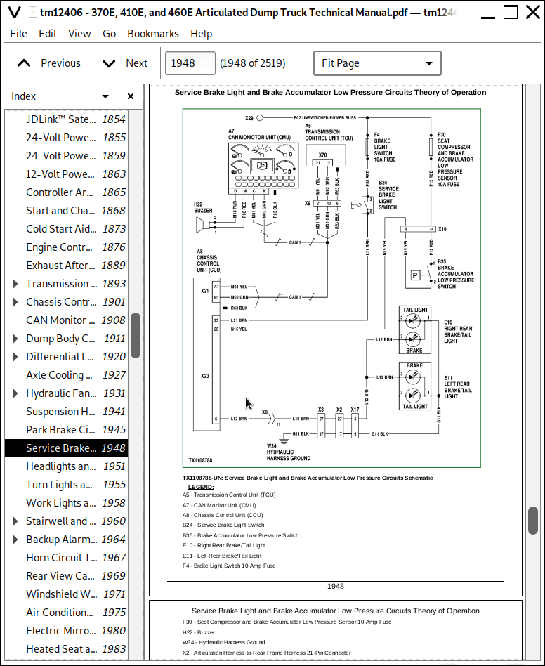
Service Brake Light and Brake Accumulator Low Pressure Circuits Theory of Operation
Headlights and Tail Lights Circuits Theory of Operation
Turn Lights and Four-Way Hazard Lights Circuits Theory of Operation
Work Lights and Rotating Beacon Circuits Theory of Operation
Stairwell and Service Lights Circuits Theory of Operation
Backup Alarm and Backup Lights Circuits Theory of Operation
Horn Circuit Theory of Operation
Rear View Camera Circuit Theory of Operation
Windshield Wipers and Washers Circuits Theory of Operation
Air Conditioner and Heater Circuits Theory of Operation
Electric Mirror Circuit Theory of Operation
Heated Seat and Air Seat Compressor Circuits Theory of Operation
Tire Pressure Monitoring (TPM) System Theory of Operation
Onboard Weighing (OBW) Controller Circuit Theory of Operation
Turbo Spin Down and Auto Shutdown Circuits Theory of Operation
JDLink™ Circuit Theory of Operation
Group 16: Monitor Operation
CAN Monitor Unit (CMU)—Service Mode
CAN Monitor Unit (CMU)—Site Limits
CAN Monitor Unit (CMU)—Codes
CAN Monitor Unit (CMU)—CCU Readings
CAN Monitor Unit (CMU)—ECU Readings
CAN Monitor Unit (CMU)—TCU Readings
CAN Monitor Unit (CMU)—OBW Readings
CAN Monitor Unit (CMU)—Calibrations
CAN Monitor Unit (CMU)—Monitor
CAN Monitor Unit (CMU)—Machine Settings
CAN Monitor Unit (CMU)—Machine Options
CAN Monitor Unit (CMU)—Software Delivery
CAN Monitor Unit (CMU)—Security
CAN Monitor Unit (CMU)—Exhaust Filter
Group 20: References
Electrical Component Specifications
Service ADVISOR™ Connection Procedure
Service ADVISOR™ Diagnostic Application
Reading Diagnostic Trouble Codes with Service ADVISOR™ Diagnostic Application
Service ADVISOR™ Diagnostic Recordings
Intermittent Diagnostic Trouble Code (DTC) Diagnostics
Using Service ADVISOR™ Remote
JDLink™ Connection Procedure
Chassis Control Unit (CCU) Outputs
Alternator Test
Relay Test
Diode Test
Controller Area Network (CAN) Circuit Test
Controller Area Network (CAN) Resistor Test
Hydraulic Pressure Switches Test
Hydraulic Pressure Sensors Test
Hydraulic Temperature Sensors Test
Strut Position Sensor Linkage Adjustment
Dump Body Position Sensor Test
Dump Body Position Sensor Calibration
Dump Body Position Sensor Adjustment
Slope Sensor Calibration
Steering Column Switch Test
Transmission Solenoids and Sensors Tests
On Board Weighing (OBW) Calibration
Onboard Weighing (OBW) Does Not Function Properly
TPM—Activating Tire Pressure Monitoring System
TPM—Programming Sensors with SmartWave® Advanced Maintenance Tool
TPM—Programming Using Sensor Identification Numbers
TPM—Cold Inflation Pressure (CIP) Setup
TPM—Alarm Setup
TPM—Delete Sensors
TPM—SmartWave® Advanced Maintenance Tool Diagnostics
TPM—Tire Pressure Sensor Remove and Install
Electronic Controllers Remove and Install
Program Monitor Display Unit (MDU)
Monitor Display Unit Remove and Install
Connector Terminal Test
Replace Metri-Pack® (Push Type) Connectors
Replace Metri-Pack® Connectors
Replace DEUTSCH® Circular Connectors
Replace DEUTSCH® Rectangular or Triangular Connectors
Install DEUTSCH® Contact
Replace WEATHER PACK® Connector
Install WEATHER PACK® Contact
Replace CINCH™ Connectors
Install CINCH™ Contact
Repair 32 and 48 Way CINCH™ Connectors
Remove Connector Body from Blade Terminals
Section 9020: Power Train
Group 05: Theory of Operation
Transmission Control System
Transmission Cross Sectional Diagram
Transmission System Schematic
Torque Converter Operation
Transmission Clutch Engagement
Transmission Retarder Operation
Transmission Inter-Axle Differential Lock (IDL) Operation
Axle Operation
Cross-Axle Differential Lock (CDL) Operation
Service Brake System Operation
Park Brake Operation
Suspension System Operation
Group 15: Diagnostic Information
Transmission External Components
Power Train Component Location
Service Brake Circuit Component Location
Axle Oil Leaking
Axle Assembly Noisy
Axle Oil Overheating
Cross-Axle Differential Lock (CDL) Does Not Work
Inter-Axle Differential Lock (IDL) Does Not Work
Auto Differential Lock (ADL) Does Not Work
Service Brake Excessive Wear
Poor or No Service Brake
Time Between Service Brake Accumulator Charging Cycles Too Short
Service Brake Noise and Vibration
Service Brakes Do Not Fully Release
Park Brake Does Not Release
Park Brake Will Not Hold
Machine Will Not Move
Transmission Will Not Shift to Forward or Reverse
Machine Creeps in Neutral
Engine Speed Too High During Torque Converter Stall
Engine Speed Too Low During Torque Converter Stall
Excessive Clutch Slippage and Chatter
Oil Comes Out of Transmission Oil Fill Tube
Buzzing Noise from Transmission
Transmission Overheating in All Gears
Transmission Not Shifting Properly (Rough Shifts, Shifting at Too-Low or Too-High Speed)
Transmission Will Not Make a Specific Shift
Transmission Retarder Does Not Function
Transmission Retarder Weak
Retarder Stays On When Not Requested
Transmission Retarder Too Aggressive
Group 25: Tests
Transmission Warmup Procedure
JT02156A Digital Pressure/Temperature Analyzer Kit Installation
Transmission Pressure Test
Transmission Clutch Drag Test
Transmission Pump Flow Test
Transmission Oil Cooler Restriction Test
Transmission Oil Cooler Thermal Bypass Valve Temperature Test
Transmission Oil Cooler Thermal Bypass Valve Pressure Test
Torque Converter—Inlet Pressure Test
Torque Converter—Outlet Flow Test and Relief Pressure Test
Torque Converter Stall Test
Torque Converter Stator Tests
Torque Converter Lockup Test
Electronic Clutch Calibration
Service Brake Accumulator Pressure Regulator Valve Test and Adjustment
Service Brake Accumulator Charge Valve Test and Adjustment
Service Brake Low Pressure Switch and Service Brake Accumulator Charge Test
Front and Rear Service Brake Accumulators Pressure Test and Charge Procedure
Service Brake Inspection
Service Brake Valve Test
Electronic Brake Valve (EBV) Test
Axle Cooling Pump Pressure Test
Axle Cooling Pump Flow Test
Park Brake Test
Park Brake Pressure Test
Park Brake Pad Thickness Check
Park Brake Adjustment
Strut Accumulator Pressure Test and Charge Procedure
Cross-Axle Differential Lock (CDL) Pressure Test and Adjustment
Inter-Axle Differential Lock (IDL) Pressure Test
Middle and Rear Axle Oil Sampling Procedure
Section 9025: Hydraulic System
Group 05: Theory of Operation
Articulated Dump Truck Hydraulic System Operation
Main Hydraulic Pump Operation
Main Hydraulic Pump Load Sense Operation
Service Brake System Operation
Steering and Secondary Steering System Operation
Steering Valve Operation
Secondary Steering Pump Operation
Hydraulic System Manifold Operation
Fan Drive System Operation
Group 15: Diagnostic Information
Hydraulic System Schematic
Hydraulic System Component Location
No Hydraulic Functions
All Hydraulic Functions Slow
Hydraulic Oil Overheats
Main Hydraulic Pump Noisy
Dump Body Will Not Rise
Hydraulic Fan Motor Not Working
Hydraulic Fan Runs at Full Speed
Poor or No Service Brakes
Service Brake Pads Excessive Wear
Time Between Service Brake Accumulator Charging Cycles Too Short
Service Brake Overheats
Service Brake Cooling Oil Leaking
Service Brake Noise and Vibration
Service Brakes Do Not Fully Release
Slow or No Steering Function
Constant Steering Needed to Maintain Straight Travel
Steering Erratic
Steering Soft or Spongy
Steering Wheel Free Play
Steering Locks Up
Steering Wheel Turns by Itself
Machine Turns in Opposite Direction as Steering Wheel
Machine Turns With Steering Valve in Neutral
Suspension System Not Working
Group 25: Test
JT02156A Digital Pressure/Temperature Analyzer Kit Installation
Hydraulic System Warmup Procedure
Cycle Time Test
Main Hydraulic Pump Margin and Maximum Pressure Test and Adjustment
Dump Body Pilot Pressure Test and Adjustment
Dump Body Manual Lowering & Bin Tip Circuit Pressure Relieving Procedure
Priority Valve Test
Service Brake Accumulator Pressure Reducing Valve Test and Adjustment
Service Brake Accumulator Charge Valve Test and Adjustment
Service Brake Low Pressure Switch and Service Brake Accumulator Charge Test
Front and Rear Service Brake Accumulators Pressure Test Procedure
Service Brake Valve Test Procedure
Electronic Brake Valve (EBV) Test Procedure
Axle Cooling Pump Pressure, Lubrication, and Flow Test
Orbital Steering Valve Leakage Test
Steering Relief Valve Pressure Test and Adjustment
Steering Cylinder Leakage Test
Dump Body Heat Diverter Valve Pressure Test
Hydraulic Fan Circuit Flow Test
Section 9031: Heating and Air Conditioning
Group 05: Theory of Operation
Air Conditioning System Cycle of Operation
Heater Core Operation
Group 15: Diagnostic Information
Air Conditioner and Heater Component Location
Air Conditioning System Does Not Operate
Air Conditioner Does Not Cool Interior of Cab
Air Conditioner Runs Constantly, Too Cold
Interior Windows Continue to Fog
Heater System Does Not Operate
Heater Does Not Warm Interior of Cab
Group 25: Tests
Refrigerant Cautions and Proper Handling
Air Conditioner and Heater Operational Checks
R134a Air Conditioning System Test
Operating Pressure Diagnostic Chart
Air Conditioner Freeze Control Switch Test
Air Conditioner Compressor Clutch Test
Air Conditioner High/Low-Pressure Switch Test
Air Conditioner Expansion Valve Test
Blower Motor Resistor/Thermofuse Test
Blower Motor Test
Expansion Valve Bench Test
Refrigerant Leak Test
John Deere Articulated Dump Trucks 370E, 410E, 460E Operation and Test Service Manual (TM12406)
![]()