
John Deere 250D and 300D Series II Articulated Dump Truck Service Manual - TM11516 (Operation & Test)

Complete service manual (Operation & Test) with Electrical Wiring Diagrams for John Deere 250D and 300D Series II (626761-642000), with all the workshop information to maintain, diagnose, and refurbish rebuild like professional mechanics.
John Deere 250D and 300D Series II Articulated Dump Truck (ADT) workshop service & repair manual includes:
* Numbered table of contents easy to use so that you can find the information you need fast.
* Detailed sub-steps expand on repair procedure information
* Numbered instructions guide you through every repair procedure step by step.
* Troubleshooting and electrical service procedures are combined with detailed wiring diagrams for ease of use.
* Notes, cautions and warnings throughout each chapter pinpoint critical information.
* Bold figure number help you quickly match illustrations with instructions.
* Detailed illustrations, drawings and photos guide you through every procedure.
* Enlarged inset helps you identify and examine parts in detail.
TM11516 - John Deere 250D and 300D Series II Articulated Dump Truck TIER 3(626761-642000) Technical Manual (Operation & Test).pdf
TM11516 - John Deere 250D and 300D Series II Articulated Dump Truck TIER 3(626761-642000) Technical Manual (Operation & Test).epub
Total Pages: 1,304 pages
File Format: PDF/EPUB/MOBI/AZW (PC/Mac/Android/Kindle/iPhone/iPad; bookmarked, ToC, Searchable, Printable)
Language: English
MAIN SECTIONS
Foreword
General Information
Safety
Diagnostic Trouble Codes (DTCs)
Chassis Control Unit (CCU) Diagnostic Trouble Codes
Engine Control Unit (ECU) Diagnostic Trouble Codes
Monitor Display Unit (MDU) Diagnostic Trouble Codes
Output Expansion Unit (OEU) Diagnostic Trouble Codes
Transmission Control Unit (TCU) Diagnostic Trouble Codes
Tire Pressure Monitor (TPM) Diagnostic Trouble Codes
Operational Checkout Procedure
Operational Checkout Procedure
Engine
Theory of Operation
Diagnostic Information
Tests
Electrical System
System Information
System Diagrams
Sub-System Diagnostics
Monitor Operation
References
Power Train
Theory of Operation
Diagnostic Information
Tests
Pneumatic System
Theory of Operation
Diagnostic Information
Tests
Hydraulic System
Theory of Operation
Diagnostic Information
Tests
Heating and Air Conditioning
Theory of Operation
Diagnostic Information
Tests
Covered models:
250D Series II (SN: 626761-642000)
300D Series II (SN: 626761-642000)
tm11516 - 250D and 300D Series II Articulated Dump Truck TIER 3(626761-642000)
Table of Contents
Foreword
Section 9000: General Information
Group 01: Safety
Recognize Safety Information
Follow Safety Instructions
Operate Only If Qualified
Wear Protective Equipment
Avoid Unauthorized Machine Modifications
Inspect Machine
Stay Clear of Moving Parts
Avoid High-Pressure Fluids
Avoid High-Pressure Oils
Beware of Exhaust Fumes
Prevent Fires
Prevent Battery Explosions
Handle Chemical Products Safely
Dispose of Waste Properly
Prepare for Emergencies
Use Steps and Handholds Correctly
Start Only From Operator's Seat
Use and Maintain Seat Belt
Prevent Unintended Machine Movement
Avoid Work Site Hazards
Keep Riders Off Machine
Avoid Backover Accidents
Avoid Machine Tip Over
Operating on Slopes
Operating or Traveling on Public Roads
Inspect and Maintain ROPS
Add and Operate Attachments Safely
Park and Prepare for Service Safely
Service Tires Safely
Service Cooling System Safely
Remove Paint Before Welding or Heating
Make Welding Repairs Safely
Drive Metal Pins Safely
Section 9001: Diagnostic Trouble Codes (DTCs)
Group 10: Chassis Control Unit (CCU) Diagnostic Trouble Codes
008000.05 - Headlight Dips Open Circuit
008000.06 - Headlight Dips Short to Ground
008000.18 - Headlight Dips Less than Normal Current
008001.05 - Headlight Brights Open Circuit
008001.06 - Headlight Brights Short to Ground
008001.18 - Headlight Brights Less than Normal Current
008002.00 - System Air Pressure Voltage too High
008002.01 - System Air Pressure Voltage too Low
008003.00 - Start Signal Voltage Too High
008004.05 - Backup Lights and Backup Alarm Open Circuit
008004.06 - Backup Lights and Backup Alarm Short to Ground
008004.18 - Backup Lights and Backup Alarm Less than Normal Current
008010.05 - Front Wiper Low Speed Open Circuit
008010.06 - Front Wiper Low Speed Short to Ground
008010.18 - Front Wiper Low Speed Less than Normal Current
008011.00 - 12 Volt Battery Voltage Too High
008011.01 - 12 Volt Battery Voltage Too Low
008012.00 - Horn Switch Short to Power
008013.05 - Park Lights Open Circuit
008013.06 - Park Lights Short to Ground
008013.18 - Park Lights Less than Normal Current
008014.01 - Switched Power Supply VP3 Too Low
008015.05 - Work Lights Open Circuit
008015.06 - Work Lights Short to Ground
008015.18 - Work Lights Less than Normal Current
008016.01 - Switched Power Supply VP6 Too Low
008017.01 - Brake Light Switch Open or Short to Ground
008018.03 - IDL Solenoid or Bin Pressure Reduction Solenoid Short to Power
008018.05 - IDL Solenoid or Bin Pressure Reduction Solenoid Open Circuit
008019.00 - Bonnet Fan Temp Switch Short to Power
008021.00 - Left Height Position Sensor Voltage Too High
008021.01 - Left Height Position Sensor Voltage Too Low
008022.01 - Hazard Light Switch Circuit Open or Short to Ground
008023.00 - Right Height Position Sensor Voltage Too High
008023.01 - Right Height Position Sensor Voltage Low
008024.03 - Bin Detent Magnet or Air System Drain Solenoid Short to Power
008024.05 - Bin Detent Magnet or Air System Drain Solenoid Open Circuit
008025.00 - Articulation Angle Position Sensor Short to Power
008025.01 - Articulation Angle Position Sensor Open Circuit
008026.00 - Bin Position Sensor Short to Power
008026.01 - Bin Position Sensor Open Circuit
008026.02 - Bin Position Sensor Voltage Erratic
008027.03 - CTD Solenoid or Rear Wiper High Speed Voltage Too High
008027.05 - CTD Solenoid or Rear Wiper High Speed Open Circuit or Short Circuit
008028.00 - Bin Lever Position Sensor Short to Power
008028.01 - Bin Lever Position Sensor Open Circuit
008030.01 - Park Brake Dash Switch Voltage Too Low
008032.03 - Beacon Light or Horn Short to Power
008032.05 - Beacon Light or Horn Open Circuit
008033.00 - Air Conditioner Evaporator Temperature Sensor Short to Power
008033.01 - Air Conditioner Evaporator Temperature Sensor Open Circuit
008034.00 - Wet Disk Brake Temperature Sensor Short to Power
008034.01 - Wet Disk Brake Temperature Sensor Open Circuit
008035.00 - Air Conditioner Evaporator Inlet Temperature Sensor Short to Power
008035.01 - Cab Temperature Voltage Too Low
008036.00 - 5-Volt Supply to Bin and Articulation Position Sensors Too High
008036.01 - 5-Volt Supply to Bin and Articulation Position Sensors Too High
008037.00 - 5-Volt Supply to Bin and Bin Lever Position Sensors Short to Power
008037.01 - 5-Volt Supply to Bin and Bin Lever Position Sensors Open Circuit
008038.01 - Switched Power Supply VP4 Too Low
008039.01 - Ignition Power via Fuse 28 Voltage Too Low
008040.00 - Alternator Voltage Too High
008040.01 - Alternator Voltage Too Low
008040.17 - Battery Voltage Too Low
008041.03 - Articulation Backup Light Short to Power
008041.05 - Articulation Backup Light Open Circuit
008042.03 - Air Conditioner Compressor or Cab Recirculation Motor Short to Power
008042.05 - Air Conditioner Compressor or Cab Recirculation Motor Open Circuit
008043.05 - Bin (Dump Body) Up Solenoid Open Circuit
008043.06 - Bin (Dump Body) Up Solenoid Short to Ground
008044.03 - Service Brake Lights Short to Power
008044.05 - Service Brake Lights Open Circuit
008045.03 - Turn Lights Short to Power
008045.05 - Turn Lights Open Circuit
008046.03 - Front Washer or Front Wiper Hi Speed Short to Power
008046.05 - Front Washer or Front Wiper Hi Speed Open Circuit
008047.03 - Hydraulic Cut-Off Solenoid or Heated Mirror Short to Power
008047.05 - Mirror Heating or Hydraulic Cut Solenoid Open Circuit
008048.05 - Bin Down Solenoid Open Circuit
008048.06 - Bin Down Solenoid Short to Ground
008049.03 - Park Brake Solenoid or Engine Overspeed Relay Short to Power
008049.05 - Park Brake Solenoid or Engine Overspeed Relay Open Circuit
008050.00 - Hydraulic Temperature Sensor Voltage Too High
008050.01 - Hydraulic Temperature Sensor Voltage Too Low
008051.01 - Ignition Power Voltage via Fuse 30 Too Low
008052.01 - Ignition Power Voltage via Fuse 31 Too Low
008053.00 - Transfer Case Temperature Too High
008100.31 - Boost Pressure Protection Activated
008101.31 - Free Wheeling
008102.31 - Excessive Idle
008103.31 - Engine Overspeed
008104.31 - Output Shaft Speed Too High
008105.31 - Bin (Dump Body) Overload
008106.31 - Harsh Braking
008107.31 - Engine Coolant Temperature Too High
008108.31 - Engine Oil Pressure Too Low
008109.31 - Transmission Oil Sump Temperature Too High
008110.31 - TCU Calibration Mismatch
008111.31 - Dynamic Park Brake Application
008112.31 - OBW Strain Gauge Error
008113.31 - Hydraulic Temperature Too High
008114.31 - Wet Disk Brake Temperature Too High
008116.31 - Tire Speed Limitation Exceeded
008117.31 - Turbo Protection Override
008118.31 - Drop Box Temperature Too High
008119.31 - Unexpected Bin (Dump Body) Direction
Group 20: Engine Control Unit (ECU) Diagnostic Trouble Codes
000091.03 - Accelerator Pedal Position Sensor Short to Power
000091.04 - Accelerator Pedal Position Sensor Open or Short to Ground
000091.08 - Accelerator Pedal Abnormal Signal
000190.00 - Engine Speed Extremely High
000523.09 - Current Gear Signal Missing
Group 30: Monitor Display Unit (MDU) Diagnostic Trouble Codes
000237.13 - CCU VIN Mismatch
000630.13 - EOL Error
000639.19 - No CAN Messages
000830.00 - Fuel Level Sensor High Voltage
000830.01 - Fuel Level Sensor Low Voltage
002000.19 - CAN Communication Lost for ECU
002003.19 - CAN Communication Lost for TCU
002033.09 - No CAN Messages
002033.19 - CAN Communication Lost for CCU
002049.19 - CAN Communication Lost for OEU
002051.19 - CAN Communication Lost for TPM
002064.19 - CAN Communication Lost for OBW
002140.19 - CAN Communication Lost for SSM
002251.19 - Loss of MMU CAN Messages
Group 40: Output Expansion Unit (OEU) Diagnostic Trouble Codes
009001.05 - Blower High Speed Open Circuit
009001.06 - Blower High Speed Short to Ground
009001.18 - Blower High Speed Less Than Normal Current
009002.05 - Blower Medium Speed Open Circuit
009002.06 - Blower Medium Speed Short to Ground
009002.18 - Blower Medium Speed Less Than Normal Current
009004.05 - Blower Low Speed Open Circuit
009004.06 - Blower Low Speed Short to Ground
009004.18 - Blower Low Speed Less Than Normal Current
009005.05 - Bonnet Fan 2 Open Circuit
009005.06 - Bonnet Fan 2 Short to Ground
009005.18 - Bonnet Fan 2 Less Than Normal Current
009006.01 - Switched Power Supply VP3 Too Low
009007.05 - Starter Open Circuit
009007.06 - Starter Short to Ground
009007.18 - Starter Less Than Normal Current
009008.01 - Ignition Supply Voltage via Fuse 19 Too Low
009009.03 - Gear Hold Voltage Too High
009009.05 - Gear Hold Open Circuit or Short Circuit
009010.03 - Green or Yellow Load Light Short to Power
009010.05 - Green or Yellow Load Light Open Circuit
009011.03 - Automatic Neutral or Pre-Select 2nd Gear Voltage Too High
009011.05 - Automatic Neutral or Pre-Select 2nd Gear Open Circuit or Short Circuit
009012.05 - Red Load Light Open Circuit
009013.01 - Switched Power Supply VP4 Too Low
009014.01 - Switched Power Supply VP5 Too Low
009015.00 - Main Switched Power Voltage Too High
009015.01 - Main Switched Power Voltage Too Low
009016.03 - Fan Low or Medium Solenoid Short to Power
009017.03 - Heater Control Valve Actuator Short to Power
009017.05 - Heater Control Valve Actuator Open Circuit
009018.05 - Engine Cooling Fan Open Circuit
009018.06 - Engine Cooling Fan Short to Ground
009019.03 - Fan Cut-Off Solenoid Short to Power
009019.05 - Fan Cut-Off Solenoid Open Circuit
009021.03 - Left Strut Up/Down Solenoid Short to Power
009021.05 - Left Strut Up/Down Solenoid Open Circuit
009022.03 - Defrost Actuator or Floor Actuator Short to Power
009022.05 - Defrost Actuator or Floor Actuator Open Circuit
009024.03 - Right Strut Up/Down Solenoid Voltage High
009024.05 - Right Strut Up/Down Solenoid Current Low
009025.01 - Switched Power Supply VP2 Too Low
009026.01 - Switched Power Supply VP2 Too Low
Group 50: Transmission Control Unit (TCU) Diagnostic Trouble Codes
005017.03 - Retarder Temperature Sensor Open or Short to Power
005017.04 - Retarder Temperature Sensor Short to Ground
005018.03 - Transmission Sump Temperature Sensor Open or Short to Power
005018.04 - Transmission Sump Temperature Sensor Short to Ground
005021.03 - Clutch A Solenoid Short to Power
005021.04 - Clutch A Solenoid Short to Ground
005021.05 - Clutch A Solenoid Open Circuit
005022.03 - Clutch B Solenoid Short to Power
005022.04 - Clutch B Solenoid Short to Ground
005022.05 - Clutch B Solenoid Open Circuit
005023.03 - Clutch C Solenoid Short to Power
005023.04 - Clutch C Solenoid Short to Ground
005023.05 - Clutch C Solenoid Open Circuit
005024.03 - Clutch D Solenoid Short to Power
005024.04 - Clutch D Solenoid Short to Ground
005024.05 - Clutch D Solenoid Open Circuit
005025.03 - Clutch E Solenoid Short to Power
005025.04 - Clutch E Solenoid Short to Ground
005025.05 - Clutch E Solenoid Open Circuit
005026.03 - Clutch F Solenoid Short to Power
005026.04 - Clutch F Solenoid Short to Ground
005026.05 - Clutch F Solenoid Open Circuit
005027.03 - Clutch G Solenoid Short to Power
005027.04 - Clutch G Solenoid Short to Ground
005027.05 - Clutch G Solenoid Open Circuit
005028.03 - Clutch WK Solenoid Short to Power
005028.04 - Clutch WK Solenoid Short to Ground
005028.05 - Clutch WK Solenoid Open Circuit
005039.05 - Shifter Lock Solenoid Open Circuit
005044.02 - Throttle Pressure D1 Solenoid Data Erratic
005044.03 - Throttle Pressure D1 Solenoid Short to Power
005044.04 - Throttle Pressure D1 Solenoid Short to Ground
005044.05 - Throttle Pressure D1 Solenoid Open Circuit
005045.03 - Retarder Proportional Solenoid Short to Power
005045.04 - Retarder Proportional Solenoid Short to Ground
005045.05 - Retarder Proportional Solenoid Open Circuit
005046.02 - Transmission Shift Control Signal Malfunction
005049.02 - Hour Counter Malfunction
005051.02 - TCU Memory Malfunction
005052.11 - TCU System Malfunction
005055.02 - TCU CAN Communication Error
005056.04 - Retarder ON Solenoid Short to Ground
005056.05 - Retarder ON Solenoid Open Circuit
005058.02 - Output Speed Sensor Signal Malfunction
005058.11 - Output Speed Sensor Signal Overflow
005059.02 - Turbine Speed Sensor Signal Malfunction
005059.11 - Turbine Speed Sensor Signal Overflow
005061.11 - TCU Checksum Malfunction
005062.03 - Retarder Resistor Open or Short to Power
005062.04 - Retarder Resistor Short to Ground
005063.14 - TCU ID Code Malfunction
005064.00 - Transmission Slip Monitoring—Limit Value Exceeded
005065.00 - Retarder Oil Temperature Over Limit
005065.14 - Retarder Oil Temperature High
005066.00 - Transmission Sump Oil Temperature Over Limit
005066.14 - Transmission Sump Oil Temperature High
005067.03 - Unused Output Short to Power
005068.12 - TCU Central Cut-Off Malfunction
005076.00 - Clutch Slippage During Power Upshift
005079.03 - Operating Voltage Above Limit
005079.04 - Operating Voltage Below Limit
005084.02 - TCU Checksum Malfunction
Group 60: Tire Pressure Monitor (TPM) Diagnostic Trouble Codes
000241.01 - Tire Second Level Alert
000241.16 - Tire First Level High Pressure Alert
000241.18 - First Level Alert Low Pressure
000242.16 - Tire High Temperature Alert
000929.12 - Tire Sensor Fault
000929.31 - Tire Eeprom Fault
007020.00 - Left Front Tire Extremely High
007020.01 - Left Front Tire Extremely Low
007020.03 - Left Front Tire High
007020.04 - Left Front Tire Low
007020.19 - Left Front Tire Error
007020.31 - Left Front Tire Undefined Malfunction
007021.00 - Left Middle Tire Extremely High
007021.01 - Left Middle Tire Extremely Low
007021.03 - Left Middle Tire High
007021.04 - Left Middle Tire Low
007021.19 - Left Middle Tire Error
007021.31 - Left Middle Tire Undefined Malfunction
007022.00 - Left Rear Tire Extremely High
007022.01 - Left Rear Tire Extremely Low
007022.03 - Left Rear Tire High
007022.04 - Left Rear Tire Low
007022.19 - Left Rear Tire Error
007022.31 - Left Rear Tire Undefined Malfunction
007023.00 - Right Tire Extremely High
007023.01 - Right Front Tire Extremely Low
007023.03 - Right Front Tire High
007023.04 - Right Front Tire Low
007023.19 - Right Front Tire Error
007023.31 - Right Front Tire Undefined Malfunction
007024.00 - Right Middle Tire Extremely High
007024.01 - Right Middle Tire Extremely Low
007024.03 - Right Middle Tire High
007024.04 - Right Middle Tire Low
007024.19 - Right Middle Tire Error
007024.31 - Right Middle Tire Undefined Malfunction
007025.00 - Right Rear Tire Extremely High
007025.01 - Right Rear Tire Extremely Low
007025.03 - Right Rear Tire High
007025.04 - Right Rear Tire Low
007025.19 - Right Rear Tire Error
007025.31 - Right Rear Tire Undefined Malfunction
Section 9005: Operational Checkout Procedure
Group 10: Operational Checkout Procedure
Operational Checkout
Section 9010: Engine
Group 05: Theory of Operation
POWERTECH 9.0L (6090) John Deere Engines
Fast Fill Fuel System Theory of Operation—If Equipped
Group 15: Diagnostic Information
POWERTECH 9.0L (6090) John Deere Engines
Engine Cooling System Component Location
Engine Fuel System Component Location
Engine Intake and Exhaust Component Location
Fast Fill Fuel System Underfill—If Equipped
Fast Fill Fuel System Overfill—If Equipped
Fast Fill Fuel System Nozzle Leaks at Receiver—If Equipped
Group 25: Tests
POWERTECH 9.0L (6090) John Deere Engines
Monitor Display Unit (MDU) Tachometer
Engine Slow and Fast Idle Speed Check
Section 9015: Electrical System
Group 05: System Information
Electrical Diagram Information
Electrical Schematic Symbols
Group 10: System Diagrams
Fuse and Relay Specifications
System Functional Schematic, Wiring Diagrams, and Component Locations Master Legend
System Functional Schematic, Wiring Diagrams, and Component Locations Master Legend With Pneumatic Control Valve—If Equipped
System Functional Schematic and Section Legend
Battery Compartment Harness (W6) Component Location
Battery Compartment Harness (W6) Wiring Diagram
Front Chassis/Engine Harness (W7) Component Location
Front Chassis/Engine Harness (W7) Wiring Diagram
Engine Control Unit (ECU) Interface Harness (W8) Component Location
Engine Control Unit (ECU) Interface Harness (W8) Wiring Diagram
Cab Harness (W10) Component Location
Cab Harness (W10) Component Location With Pneumatic Control Valve—If Equipped
Cab Harness (W10) Wiring Diagram
Cab Harness (W10) Wiring Diagram With Pneumatic Control Valve—If Equipped
Transmission Valve Control Module Harness (W11) Component Location
Transmission Valve Control Module Harness (W11) Wiring Diagram
Transmission Control Harness (W12) Component Location
Transmission Control Harness (W12) Wiring Diagram
Transmission Harness (W13) Component Location
Transmission Harness (W13) Wiring Diagram
Hydraulic Harness (W14) Component Location
Hydraulic Harness (W14) Wiring Diagram
Rear Chassis Harness (W15) Component Location
Rear Chassis Harness (W15) Wiring Diagram
Work Light Harness (W16) Component Location
Work Light Harness (W16) Wiring Diagram
Air Conditioner Actuator Harness (W18) Component Location
Air Conditioner Actuator Harness (W18) Wiring Diagram
Articulation Harness (W19) Component Location
Articulation Harness (W19) Wiring Diagram
AM/FM Radio Harness (W20) Component Location
AM/FM Radio Harness (W20) Wiring Diagram
JDLink™ System Harnesses Component Location—MIG/GTT
JDLink™ System Harnesses Component Location—MTG/SAT
JDLink™ System Wiring Diagrams—MIG/GTT
JDLink™ System Wiring Diagrams—MTG/SAT
On Board Weighing (OBW) and Tire Pressure Monitoring (TPM) System Harness (W30) Component Location
On Board Weighing (OBW) and Tire Pressure Monitoring (TPM) System Harness (W30) Wiring Diagram
Seat Heater Harness (W33) Component Location
Seat Heater Harness (W33) Wiring Diagram
Pneumatic Control Valve Harness (W40) Wiring Diagram—If Equipped
Group 15: Sub-System Diagnostics
Start and Charge Circuit Theory of Operation
Controller Area Network (CAN) Circuit Theory of Operation
Engine Control Unit (ECU) Circuit Theory of Operation
Transmission Control Unit (TCU) and Retarder Circuit Theory of Operation
Chassis Control Unit (CCU) Circuit Theory of Operation
Output Expansion Unit (OEU) Circuit Theory of Operation
Bin (Dump Body) Control and Gear Limit Circuit Theory of Operation
Inter-Axle Differential Lock (IDL) Circuit Theory of Operation
Park Brake Circuit Theory of Operation
Monitor Display Unit (MDU) Circuit Theory of Operation
Turn Lights and Four-Way Flasher Circuit Theory of Operation
Backup Alarm and Backup Light Circuit Theory of Operation
Service Brake Light Circuit Theory of Operation
Wiper and Washer Circuit Theory of Operation
24/12 V Voltage Converter Theory of Operation
Air Conditioning Circuit Theory of Operation
Electric Mirror Circuit Theory of Operation
Unloader Valve Heater Circuit Theory of Operation
Tire Pressure Monitoring (TPM) System Theory of Operation
On Board Weighing (OBW) Controller Circuit Theory of Operation
Turbo Spin Down and Idle Shutdown (Auto Shutdown) Circuit Theory of Operation
JDLink™ Circuit Theory of Operation—If Equipped
Group 16: Monitor Operation
Monitor Display Unit (MDU)—Service Mode
Monitor Display Unit (MDU)—Service Interval Reset
Monitor Display Unit (MDU)—Clear Stored DTC
Monitor Display Unit (MDU)—Engine Torque Values
Monitor Display Unit (MDU)—Output Diagnostics
Monitor Display Unit (MDU)—Gear Selector
Monitor Display Unit (MDU)—Site Limit
Monitor Display Unit (MDU)—Safety Limit
Monitor Display Unit (MDU)—Prevent Tip
Monitor Display Unit (MDU)—Tire Size
Monitor Display Unit (MDU)—Position Sensors
Monitor Display Unit (MDU)—Hydraulic Pressure Setup
Monitor Display Unit (MDU)—Custom Hydraulic Setup
Monitor Display Unit (MDU)—OBW Configuration
Monitor Display Unit (MDU)—LCD Offset
Monitor Display Unit (MDU)—Enable Options
Monitor Display Unit (MDU)—Enable Load Spreading
Group 20: References
Electrical Component Specifications
Service ADVISOR™ Connection Procedure
Service ADVISOR™ Diagnostic Application
Reading Diagnostic Trouble Codes with Service ADVISOR™ Diagnostic Application
Intermittent Diagnostic Trouble Code (DTC) Diagnostics
JDLink™ System Identification
JDLink™ Connection Procedure—If Equipped
Alternator Test
Relay Test
Diode Test
Controller Area Network (CAN) Circuit Testing
Controller Area Network (CAN) Resistor Test
Pneumatic System Solenoids, Pressure Switches, and Sensor Tests
Hydraulic Pressure Switches Test
Hydraulic Temperature Sensors Test
Bin (Dump Body) Position Sensor Calibration
Dump Body Position Sensor Test
Incline Sensor Calibration—If Equipped
Steering Column Switch Test
Transmission Solenoids, Speed Sensors, Sump Temperature Sensor, and Retarder Resistor Tests
Retarder Proportional Solenoid Test
Retarder Temperature Sensor Test
On Board Weighing (OBW) Calibration
Foot Throttle Calibration Procedure
TPM—Activating Tire Pressure Monitoring System
TPM—Programming Sensors with SmartWave® Advanced Maintenance Tool
TPM—Programming Using Sensor Identification Numbers
TPM—Cold Inflation Pressure (CIP) Setup
TPM—SmartWave® Advanced Maintenance Tool Diagnostics
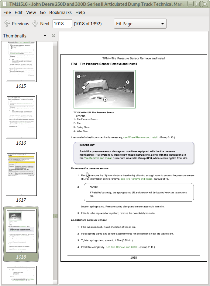
TPM—Tire Pressure Sensor Remove and Install
Electronic Controllers Remove and Install
Program Monitor Display Unit (MDU)
Monitor Display Unit Remove and Install
Accelerator Pedal Position Sensor Remove and Install
Connector Terminal Test
Replace Metri-Pack® (Push Type) Connectors
Replace Metri-Pack® Connectors
Replace DEUTSCH® Circular Connectors
Replace DEUTSCH® Rectangular or Triangular Connectors
Install DEUTSCH® Contact
Replace WEATHER PACK® Connector
Install WEATHER PACK® Contact
Replace CINCH™ Connectors
Install CINCH™ Contact
Repair 32 and 48 Way CINCH™ Connectors
Remove Connector Body from Blade Terminals
Section 9020: Power Train
Group 05: Theory of Operation
Transmission Control System
Transmission Cross Sectional Diagram
Torque Converter Operation
Transmission Clutch Engagement
Transmission Retarder Operation
Service Brake System Operation
Transfer Case and Inter-Axle Differential Lock (IDL) Operation
Group 15: Diagnostic Information
Transmission External Components
Power Train Component Location
Service Brake Circuit Component Location
Axle Breather Leaking
Final Drive Overheating
Final Drive Noisy
Final Drive Leaking Oil
Differential Assembly Noisy and/or Overheating
Service Brake Pads Excessive Wear
Poor or No Service Brakes
Service Brakes Do Not Fully Release
Time Between Service Brake Accumulator Charging Cycles Too Short
Park Brake Does Not Release
Park Brake Will Not Hold
Machine Will Not Move
Transmission Will Not Shift to Forward or Reverse
Engine Speed Too Low During Torque Converter Stall
Low Transmission Lube Pressure
Low Main Pressure in All Gears
Excessive Clutch Slippage and Chatter
Oil Comes Out of Transmission Oil Fill Tube
Buzzing Noise from Transmission
Transmission Overheating in All Gears
Transmission Not Shifting Properly (Rough Shifts, Shifting at Too-Low or Too-High Speed)
Transmission Will Not Make a Specific Shift
Transmission Oil Leaking into Torque Converter Housing
Transmission Retarder Does Not Function
Transmission Retarder Weak
Retarder Stays On When Not Requested
Transmission Retarder Too Aggressive
Group 25: Tests
Transmission Warmup Procedure
JT02156A Digital Pressure/Temperature Analyzer Kit Installation
Transmission Pressure Test
Torque Converter Stall Test
Torque Converter Stator Tests
Transmission Oil-to-Air Cooler Restriction Test
Front Suspension Strut Leakage Check
Front Axle Suspension Strut Height Check
Service Brake Accumulator Pressure Reducing Valve Test and Adjustment
Service Brake Accumulator Charge Valve Test and Adjustment
Service Brake Low Pressure Switch Test
Front and Rear Service Brake Apply Accumulators Pressure Test and Charge Procedure
Service Brake Valve Test
Park Brake Test
Park Brake Pressure Test
Park Brake Pad Thickness Check
Park Brake Adjustment
Wheel Hub Bearing Preload Adjustment (Wheel Installed)
Section 9022: Pneumatic System
Group 05: Theory of Operation
Pneumatic System Operation
Pneumatic System Operation With Pneumatic Control Valve—If Equipped
Air Pressure Supply Circuit Operation
Air Dryer and Unloader Valve
Group 15: Diagnostic Information
Pneumatic System Schematic
Pneumatic System Schematic With Pneumatic Control Valve—If Equipped
Pneumatic System Component Location
Pneumatic System Component Location With Pneumatic Control Valve—If Equipped
Pneumatic Manifold Component Location
Pneumatic System Will Not Reach Operating Pressure
Park Brake Will Not Release
Inter-Axle Differential Lock (IDL) Will Not Operate
Air Horn Will Not Operate
Group 25: Tests
Pneumatic System Main Pressure Test and Adjustment
Park Brake Pressure Test
Section 9025: Hydraulic System
Group 05: Theory of Operation
Articulated Dump Truck Hydraulic System Operation
Main Hydraulic Pump Operation
Main Hydraulic Pump Load Sense Operation
Service Brake System Operation
Steering and Secondary Steering System Operation
Steering Valve Operation
Secondary Steering Pump Operation
Hydraulic System Manifold Operation
Dump Body Control Valve Operation
Group 15: Diagnostic Information
Hydraulic System Schematic
Hydraulic System Component Location
No Hydraulic Functions
All Hydraulic Functions Slow
Hydraulic Oil Overheats
Main Hydraulic Pump Noisy
Bin (Dump Body) Will Not Rise
Onboard Weighing (OBW) Does Not Function Properly
Poor or No Service Brakes
Service Brake Pads Excessive Wear
Service Brakes Do Not Fully Release
Time Between Service Brake Accumulator Charging Cycles Too Short
Slow or No Steering Function
Constant Steering Needed to Maintain Straight Travel
Steering Erratic
Steering Soft or Spongy
Steering Wheel Free Play
Steering Locks Up
Abrupt Steering Wheel Oscillation
Steering Wheel Turns by Itself
Machine Turns in Opposite Direction as Steering Wheel
Machine Turns With Steering Valve in Neutral
Group 25: Tests
JT02156A Digital Pressure/Temperature Analyzer Installation
Hydraulic System Warmup Procedure
Cycle Time Test
Main Hydraulic Pump Residual and Compensator Valves Test and Adjustment
System Relief Valve and Bin (Dump Body) Raise Circuit Relief Valve Test
Priority Valve Test
Service Brake Accumulator Pressure Reducing Valve Test and Adjustment
Service Brake Accumulator Charge Valve Test and Adjustment
Service Brake Low Pressure Switch Test
Front and Rear Service Brake Apply Accumulators Pressure Test and Charge Procedure
Service Brake Valve Test
Steering Relief Valve Pressure Test and Adjustment
Steering Cylinder Leakage Test
Secondary Steering Pump Residual and Compensator Valves Test and Adjustment
Bin (Dump Body) Lower Circuit Relief Valve Test
Pilot Pressure Regulating Valve Test and Adjustment
Section 9031: Heating and Air Conditioning
Group 05: Theory of Operation
Air Conditioning System Cycle of Operation
Heater Core Operation
Group 15: Diagnostic Information
Air Conditioner and Heater Component Location
Air Conditioning System Does Not Operate
Air Conditioner Does Not Cool Interior of Cab
Air Conditioner Runs Constantly, Too Cold
Interior Windows Continue to Fog
Heater System Does Not Operate
Heater Does Not Warm Interior of Cab
Group 25: Tests
Refrigerant Cautions and Proper Handling
Air Conditioner and Heater Operational Checks
R134a Air Conditioning System Test
Operating Pressure Diagnostic Chart
Air Conditioner Freeze Control Switch Test
Air Conditioner Compressor Clutch Test
Air Conditioner High/Low Pressure Switch Test
Air Conditioner Expansion Valve Test
Blower Motor Resistor/Thermofuse Test
Blower Motor Test
Expansion Valve Bench Test
Refrigerant Leak Test
John Deere 250D and 300D Series II Articulated Dump Truck Service Manual - TM11516 (Operation & Test)
![]()