
John Deere Articulated Dump Trucks 370E, 410E, 460E Repair Service Manual (TM13032)

Complete service repair manual for John Deere Articulated Dump Trucks (ADT) 370E, 410E, 460E (T3/S3A), with workshop information to maintain, repair, and service like professional mechanics.
John Deere Articulated Dump Trucks 370E, 410E, 460E workshop service repair manual includes:
* Numbered table of contents easy to use so that you can find the information you need fast.
* Detailed sub-steps expand on repair procedure information
* Numbered instructions guide you through every repair procedure step by step.
* Notes, cautions and warnings throughout each chapter pinpoint critical information.
* Bold figure number help you quickly match illustrations with instructions.
* Detailed illustrations, drawings and photos guide you through every procedure.
* Enlarged inset helps you identify and examine parts in detail.
TM13032 - John Deere 370E, 410E, 460E Articulated Dump Truck Technical Manual - Repair.PDF
TM13032 - John Deere 370E, 410E, 460E Articulated Dump Truck Technical Manual - Repair.EPUB
Total Pages: 931 pages
File Format: PDF/EPUB/MOBI/AZW (PC/Mac/Android/Kindle/iPhone/iPad; bookmarked, ToC, Searchable, Printable)
Language: English
370E (PIN: 1DW370E***D634583-668586)
410E (PIN: 1DW410E***D634583-668586)
460E (PIN: 1DW460E***D634583-668586)
MAIN SECTIONS (SN:D634583-668586)
Foreword
Manual Identification-READ THIS FIRST!
General Information
Safety
Wheels
Removal and Installation
Axles and Suspension Systems
Removal and Installation
Input Drive Shafts and U-Joints
Axle Mounting Parts
Axle Shaft, Bearings, and Reduction Gears
Hydraulic System
Transmission
Removal and Installation
Input Drive Shafts and U-Joints
Gear, Shafts, and Power Shift Clutches
Hydraulic System
Engine
Removal and Installation
Engine Auxiliary System
Cold Weather Starting Aids
Cooling Systems
Intake System
External Exhaust Systems
External Fuel Supply Systems
Damper Drive
Elements
Steering System
Secondary Steering
Hydraulic System
Service Brakes
Active Elements
Hydraulic System
Park Brake
Active Elements
Hydraulic System
Frame or Supporting Structure
Frame Installation
Operator`s Station
Operator Enclosure
Seat and Seat Belt
Heating and Air Conditioning
Sheet Metal and Styling
Hood or Engine Enclosure
Fenders
Main Hydraulic System
Hydraulic System
Haulage Device
Frames
Hydraulic System
Dealer Fabricated Tools
tm13032 - 370E, 410E, and 460E Articulated Dump Truck
Table of Contents
Foreword
Manual Identification—READ THIS FIRST!
Section 00: General Information
Group 0001: Safety
Safety and Operator Convenience Features
Recognize Safety Information
Follow Safety Instructions
Operate Only If Qualified
Wear Protective Equipment
Avoid Unauthorized Machine Modifications
Inspect Machine
Stay Clear of Moving Parts
Avoid High-Pressure Fluids
Avoid High-Pressure Oils
Work In Ventilated Area
Prevent Fires
Prevent Battery Explosions
Handle Chemical Products Safely
Decommissioning — Proper Recycling and Disposal of Fluids and Components
Prepare for Emergencies
Clean Debris from Machine
Use Steps and Handholds Correctly
Start Only From Operator's Seat
Use and Maintain Seat Belt
Prevent Unintended Machine Movement
Avoid Work Site Hazards
Keep Riders Off Machine
Avoid Backover Accidents
Avoid Machine Tip Over
Operating on Slopes
Operating or Traveling On Public Roads
Inspect and Maintain ROPS
Add and Operate Attachments Safely
Prepare Machine for Maintenance
Park and Prepare for Service Safely
Service Cooling System Safely
Remove Paint Before Welding or Heating
Make Welding Repairs Safely
Drive Metal Pins Safely
Service Tires Safely
Group 0003: Torque Values
Metric Bolt and Cap Screw Torque Values
Additional Metric Cap Screw Torque Values
Unified Inch Bolt and Cap Screw Torque Values
Service Recommendations for 37° Flare and 30° Cone Seat Connectors
Service Recommendations for O-Ring Boss Fittings
O-Ring Boss Fittings in Aluminum Housing Service Recommendations—Excavators
Service Recommendations for Flared Connections—Straight or Tapered Threads
Service Recommendations for Flat Face O-Ring Seal Fittings
O-Ring Face Seal Fittings With SAE Inch Hex Nut and Stud End for High-Pressure Service Recommendations
O-Ring Face Seal Fittings With Metric Hex Nut and Stud End for Standard Pressure Service Recommendations
O-Ring Face Seal Fittings With Metric Hex Nut and Stud End for High-Pressure Service Recommendations
Service Recommendations for Metric Series Four Bolt Flange Fitting
Service Recommendations For Inch Series Four Bolt Flange Fittings
Inch Series Four Bolt Flange Fitting for High-Pressure Service Recommendations
Service Recommendations For Non-Restricted Banjo (Adjustable) Fittings
Service Recommendations For O-Ring Boss Fittings With Shoulder
Metric 24° O-Ring Seal DIN 20078 Service Recommendations
Section 01: Wheels
Group 0100: Removal and Installation
Wheel Remove and Install
Tire Remove and Install
Section 02: Axles and Suspension Systems
Group 0200: Removal and Installation
TeamMate V 1500 Series Axle
Front Axle Remove and Install
Middle or Rear Axle Remove and Install
Group 0225: Input Drive Shafts and U-Joints
Transmission-to-Front Axle Drive Shaft or Transmission-to-Oscillation Joint Drive Shaft Remove and Install
Oscillation Joint Drive Shaft Remove and Install
Park Brake-to-Middle Axle Drive Shaft Remove and Install
Middle Axle-to-Rear Axle Drive Shaft Remove and Install
Group 0242: Axle Mounting Parts
Front Suspension Strut Remove and Install
Front Suspension Accumulator Remove and Install
Axle Links and Stabilizers Remove and Install
Axle Link, Stabilizer, and Strut Bushing Replace
Front Axle Pivot Disassemble and Assemble
Walking Beam Remove and Install
Walking Beam Bushing Remove and Install
Middle and Rear Axle Rubber Mount Remove and Install
Strain Gauge Remove and Install
Group 0250: Axle Shaft, Bearings, and Reduction Gears
TeamMate V 1500 Series Axle
Group 0260: Hydraulic System
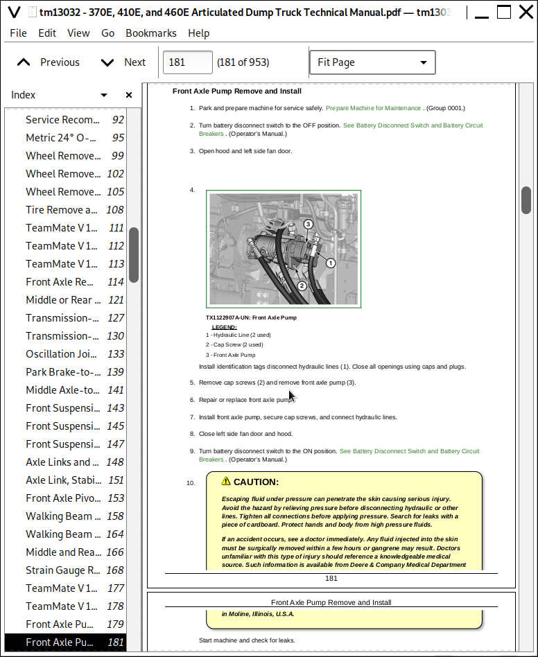
Front Axle Pump Remove and Install
Rear Axle Pump Remove and Install
Front Axle Cooling Manifold Remove and Install
Middle Axle Cooling Manifold Remove and Install
Rear Axle Cooling Manifold Remove and Install
Comfort Ride Control Valve Remove and Install
Strut Accumulator Remove and Install
Active Suspension Manifold Disassemble and Assemble
Axle Cooling Manifold Disassemble and Assemble
Section 03: Transmission
Group 0300: Removal and Installation
Transmission Remove and Install
Transmission Alignment
Front Transmission Mount Washer Installation
Group 0325: Input Drive Shafts and U-Joints
Engine-to-Transmission Drive Shaft Remove and Install
Group 0350: Gear, Shafts, and Power Shift Clutches
Transmission Disassemble
Transmission Assemble
Transmission Clutch (F) Hi/Lo Planetary Disassemble and Assemble
Transmission Clutch (E) Disassemble and Assemble
Transmission Clutch (R) Disassemble and Assemble
Transmission Clutch (B) Disassemble and Assemble
Transmission Clutch (V) Disassemble and Assemble
Transmission Clutch (C) Disassemble and Assemble
Transmission Clutch (D) Disassemble and Assemble
Transmission Clutch (A) Disassemble and Assemble
Transmission Clutch (G) Inter-Axle Differential Lock (IDL) Disassemble and Assemble
Transmission Speed Sensors Remove and Install
Transmission Clutch (F) Hi/Lo Planetary Remove and Install
Group 0360: Hydraulic System
Transmission Oil Cooler Thermal Bypass Valve Remove and Install
Transmission Control Valve Remove and Install
Torque Converter Remove and Install
Clutch Control Valve Remove and Install
Retarder Control Valve Remove and Install
Oil Pump Remove and Install
Transmission Retarder Remove and Install
Transmission Control Valve Disassemble and Assemble
Clutch Control Valve Disassemble and Assemble
Retarder Control Valve Disassemble and Assemble
Oil Pump Disassemble and Assemble
Transmission Retarder Disassemble and Assemble
Section 04: Engine
Group 0400: Removal and Installation
John Deere Engine Theory of Operation
Engine Remove
Engine Install
Engine Crankshaft Damper Remove and Install
Serpentine Belt Remove and Install
Section 05: Engine Auxiliary System
Group 0505: Cold Weather Starting Aids
Cold Start Aid—Starting Fluid Nozzle Remove and Install—If Equipped
Cold Start Aid—Starting Fluid Solenoid Remove and Install—If Equipped
Cold Start Aid—Block Heater Remove and Install—If Equipped
Group 0510: Cooling Systems
Charge Air Cooler Remove and Install
Left Radiator Remove and Install
Right Radiator Remove and Install
Hydraulic Oil Cooler Remove and Install
Transmission Oil Cooler Remove and Install
Fuel Cooler Remove and Install
Front Axle Oil Cooler Remove and Install
Middle Axle Oil Cooler Remove and Install
Group 0520: Intake System
Air Cleaner Remove and Install
Group 0530: External Exhaust Systems
Muffler and Exhaust Pipe Remove and Install
Dump Body Heater Pipe Remove and Install
Dump Body Heater Exhaust Collar Adjust
Group 0560: External Fuel Supply Systems
Fuel Tank Remove and Install
Fuel Transfer Pump Remove and Install
Fast Fill Fuel System Disassemble and Assemble—If Equipped
Section 07: Damper Drive
Group 0752: Elements
Output Damper Remove and Install
Section 09: Steering System
Group 0930: Secondary Steering
Secondary Steering Pump Remove and Install
Steering Wheel and Column Remove and Install
Steering Column Disassemble and Assemble
Group 0960: Hydraulic System
Steering Valve Remove and Install
Steering Valve Disassemble and Assemble
Steering Cylinder Remove and Install
Steering Bushing Replacement
Section 10: Service Brakes
Group 1011: Active Elements
Service Brake Assembly Remove and Install
Group 1060: Hydraulic System
Bleed Service Brake
Brake Accumulator Remove and Install
Brake Valve Remove and Install
Electronic Brake Valve Remove and Install
Section 11: Park Brake
Group 1111: Active Elements
Park Brake Pads Remove and Install
Park Brake Caliper Remove and Install
Park Brake Disk Remove and Install
Park Brake Chamber Remove and Install
Group 1160: Hydraulic System
Park Brake Control Valve Remove and Install
Section 17: Frame or Supporting Structure
Group 1740: Frame Installation
Welding on Machine
Front and Rear Frames Separate
Articulation Frame Remove and Install
Articulation Frame Bearings Disassemble and Assemble
Articulation Frame Bearings Adjust
Oscillation Joint Disassemble and Assemble
Oscillation Joint Bearing Cap Screw Installation
Section 18: Operator's Station
Group 1810: Operator Enclosure
Cab Remove and Install
Cab Mount Remove and Install
Cab Tilt Pump and Cylinder Remove and Install
Windowpanes Remove and Install
Cab Door Window Installation
Group 1821: Seat and Seat Belt
Operator’s Seat Remove and Install
Seat Belt Remove and Install
Group 1830: Heating and Air Conditioning
R134a Refrigerant Cautions and Proper Handling
R134a Refrigerant Oil Information
R134a Refrigerant Recovery/Recycling and Charging Station Installation Procedure
R134a Refrigerant Recover
Air Conditioning System Flush and Purge
R134a System Evacuate
R134a System Charge
Compressor Remove and Install
Condenser Remove and Install
High/Low Pressure Switch Remove and Install
Receiver-Dryer Remove and Install
Expansion Valve Remove and Install
Heater Core and Evaporator Core Remove and Install
Freeze Control Switch Remove and Install
Heater Control Valve Remove and Install
Heater Control Valve Leak Check
Blower Motor Assembly Remove and Install
Vent Actuator Remove and Install
Section 19: Sheet Metal and Styling
Group 1910: Hood or Engine Enclosure
Hood Remove and Install
Hood Adjust
Engine Service Door Remove and Install
Left Fan Grille Remove and Install
Right Fan Grille Remove and Install
Group 1927: Fenders
Fender Remove and Install
Section 21: Main Hydraulic System
Group 2160: Hydraulic System
Main Hydraulic Pump Remove and Install
Hydraulic Reservoir Remove and Install
Dump Body Heat Cylinder Remove and Install
Dump Body Heat Diverter Valve Remove and Install
Hydraulic System Manifold Remove and Install
Hydraulic System Manifold Disassemble and Assemble
Hydraulic Fan Motor Right Side Remove and Install
Hydraulic Fan Motor Left Side Remove and Install
Reversing Hydraulic Fan Motor Left Side Remove and Install (if equipped)
Reversing Hydraulic Fan Motor Right Side Remove and Install (if equipped)
Left Hydraulic Fan Pump Remove and Install
Right Hydraulic Fan Pump Remove and Install
Hydraulic Attenuator Remove and Install
General Oil Cleanup Procedure
Hydraulic Component Failure Cleanup Procedure
Section 35: Haulage Device
Group 3540: Frames
Dump Body Remove and Install
Dump Body Align
Tailgate Remove and Install
Group 3560: Hydraulic System
Dump Body Lift Cylinder Remove and Install
Dump Body Lift Cylinder Disassemble and Assemble
Dump Body Lift Cylinder Head End Pivot Pin Bushing Remove and Install
Dump Body Lift Cylinder Rod End Pivot Pin Bushing Remove and Install
Section 99: Dealer Fabricated Tools
Group 9900: Dealer Fabricated Tools
DFT1344 Supports
DFT1187 Bearing Driver
DFT1196 Bushing Driver
DFT1199 Bushing Pusher
DFT1200 Bushing Driver
DFT1353 Strain Gauge Alignment Tool
John Deere Articulated Dump Trucks 370E, 410E, 460E Repair Service Manual (TM13032)
![]()