
John Deere Articulated Dump Trucks 370E, 410E, 460E Operation and Test Service Manual (TM13378X19)

Complete technical manual with electrical wiring diagrams for John Deere Articulated Dump Trucks 370E, 410E, 460E, with all the shop information to maintain, diagnose, and service like professional mechanics.
John Deere Articulated Dump Trucks 370E, 410E, 460E workshop diagnosis and Test manual includes:
* Numbered table of contents easy to use so that you can find the information you need fast.
* Detailed sub-steps expand on repair procedure information
* Numbered instructions guide you through every repair procedure step by step.
* Troubleshooting and electrical service procedures are combined with detailed wiring diagrams for ease of use.
* Notes, cautions and warnings throughout each chapter pinpoint critical information.
* Bold figure number help you quickly match illustrations with instructions.
* Detailed illustrations, drawings and photos guide you through every procedure.
* Enlarged inset helps you identify and examine parts in detail.
TM13378X19 - John Deere 370E, 410E, 460E Articulated Dump Truck Technical Manual - Operation and Test.PDF
TM13378X19 - John Deere 370E, 410E, 460E Articulated Dump Truck Technical Manual - Operation and Test.EPUB
Total Pages: 1,820 pages
File Format: PDF/EPUB/MOBI/AZW (PC/Mac/Android/Kindle/iPhone/iPad; bookmarked, ToC, Searchable, Printable)
Language: English
(SN.F668588-)
370E (PIN: 1DW370E***F668588-)
410E (PIN: 1DW410E***F668589-)
460E (PIN: 1DW460E***F668587-)
MAIN SECTIONS
Foreword
Manual Identification-READ THIS FIRST!
General Information
Safety
Diagnostics
Transmission Control Unit (TCU) Diagnostic Trouble Codes
Engine Control Unit (ECU) Diagnostic Trouble Codes
Vehicle Control Unit (VCU) Diagnostic Trouble Codes
Display Menu Handler (DMH) Diagnostic Trouble Codes
Sealed Switch Module 1 (SM1) Diagnostic Trouble Codes
Sealed Switch Module 2 (SM2) Diagnostic Trouble Codes
Primary Display Unit (PDU) Diagnostic Trouble Codes
Rear Frame Controller (RFC) Diagnostic Trouble Codes
Tire Pressure Monitoring (TPM) System Diagnostic Trouble Codes
Automatic Temperature Control (ATC) Diagnostic Trouble Codes
Operational Checkout Procedure
Operational Checkout Procedure
Engine
Theory of Operation
System Diagrams
Diagnostic Information
Adjustments
Tests
Electrical System
Theory of Operation
System Diagrams
Diagnostic Information
Primary Display Unit (PDU) Operation
Diagnostic Test Box
Adjustments
Tests
Power Train
Theory of Operation
System Diagrams
Diagnostic Information
Tests
Hydraulic System
Theory of Operation
System Diagrams
Diagnostic Information
Test
Heating and Air Conditioning
Theory of Operation
Diagnostic Information
Tests
tm13378x19 - 370E, 410E, and 460E Articulated Dump Truck
Table of Contents
Foreword
Manual Identification—READ THIS FIRST!
Section 9000: General Information
Group 01: Safety
Recognize Safety Information
Follow Safety Instructions
Operate Only If Qualified
Wear Protective Equipment
Avoid Unauthorized Machine Modifications
Inspect Machine
Stay Clear of Moving Parts
Avoid High-Pressure Fluids
Avoid High-Pressure Oils
Work In Ventilated Area
Handle Starting Fluid Safely
Avoid Static Electricity Risk When Refueling
Prevent Fires
In Case of Machine Fire
Prevent Battery Explosions
Handle Chemical Products Safely
Decommissioning — Proper Recycling and Disposal of Fluids and Components
Exhaust Filter Ash Handling and Disposal
Prepare for Emergencies
Clean Debris from Machine
Use Steps and Handholds Correctly
Start Only From Operator's Seat
Use and Maintain Seat Belt
Prevent Unintended Machine Movement
Avoid Work Site Hazards
Keep Riders Off Machine
Prevent Acid Burns
Avoid Backover Accidents
Avoid Machine Tip Over
Operating on Slopes
Operating or Traveling On Public Roads
Inspect and Maintain ROPS
Keep the Operator Protective Structure (OPS) in Place
Travel Safely
Add and Operate Attachments Safely
Park and Prepare for Service Safely
Service Cooling System Safely
Remove Paint Before Welding or Heating
Make Welding Repairs Safely
Drive Metal Pins Safely
Service Tires Safely
Clean Exhaust Filter Safely
Section 9001: Diagnostics
Group 10: Transmission Control Unit (TCU) Diagnostic Trouble Codes
523000.01 - Controller Power Source Fault
523000.03 - Controller Power Source Fault
523000.04 - Unswitched Power Circuit Fault
523001.01 - Unswitched Power Fault
523010.03 - Sensor Supply Circuit Fault
523010.04 - Sensor Supply Circuit Fault
523011.04 - Internal Controller Supply Circuit Fault
523020.03 - Sensor Supply Circuit Fault
523020.04 - Sensor Supply Circuit Fault
523020.06 - Sensor Supply Circuit Fault
523021.03 - Sensor Supply Circuit Fault
523021.04 - Sensor Supply Circuit Fault
523021.06 - Sensor Supply Circuit Fault
523022.03 - Sensor Supply Circuit Fault
523022.04 - Sensor Supply Circuit Fault
523022.06 - Sensor Supply Circuit Fault
523030.03 - Controller Valve Power Supply Circuit Fault
523030.04 - Controller Valve Power Supply Circuit Fault
523030.06 - Controller Power Source Fault
523031.03 - Controller Valve Power Supply Circuit Fault
523031.04 - Controller Valve Power Supply Circuit Fault
523031.06 - Controller Power Source Fault
523040.00 - Controller Temperature High
523040.02 - Internal Controller Temperature High
523045.12 - Controller Fault
523046.12 - Controller Fault
523047.12 - Controller Fault
523048.12 - Controller Fault
523049.12 - Controller Fault
523100.02 - Turbine Speed Sensor Fault
523100.03 - Turbine Speed Sensor Fault
523100.06 - Turbine Speed Sensor Fault
523100.07 - Turbine Speed Sensor Fault
523100.08 - Turbine Speed Sensor Fault
523100.09 - Turbine Speed Sensor Fault
523100.11 - Turbine Speed Sensor Fault
523105.02 - Unknown Connection
523105.03 - Internal Speed Sensor Fault
523105.06 - Internal Speed Sensor Fault
523105.07 - Internal Speed Sensor Fault
523105.08 - Internal Speed Sensor Fault
523105.09 - Internal Speed Sensor Fault
523105.11 - Internal Speed Sensor Fault
523110.02 - Unknown Connection
523110.03 - Internal Speed Sensor Fault
523110.06 - Internal Speed Sensor Fault
523110.07 - Internal Speed Sensor Fault
523110.08 - Internal Speed Sensor Fault
523110.09 - Internal Speed Sensor Fault
523110.11 - Internal Speed Sensor Fault
523115.02 - Unknown Connection
523115.03 - Output Speed Sensor Fault
523115.06 - Output Speed Sensor Fault
523115.07 - Output Speed Sensor Fault
523115.08 - Output Speed Sensor Fault
523115.09 - Output Speed Sensor Fault
523115.11 - Output Speed Sensor Fault
523125.02 - Transmission Invalid Component Circuit Fault
523130.02 - Unknown Connection
523140.02 - Unknown Connection
523140.03 - Transmission Sump Temperature Sensor Fault
523140.05 - Transmission Sump Temperature Sensor Fault
523140.06 - Transmission Sump Temperature Sensor Fault
523145.02 - Unknown Connection
523145.03 - Retarder Temperature Sensor Fault
523145.05 - Retarder Temperature Sensor Fault
523145.06 - Retarder Temperature Sensor Fault
523150.02 - Unknown Connection
523155.02 - Unknown Connection
523155.03 - Transmission Oil Filter Fault
523155.04 - Transmission Oil Filter Fault
523155.06 - Transmission Oil Filter Fault
523200.00 - Clutch A Slip
523200.02 - Unknown Connection
523200.03 - Controller Valve Power Supply Circuit Fault
523200.05 - Controller Valve Power Supply Circuit Fault
523200.06 - Controller Valve Power Supply Circuit Fault
523200.08 - Clutch A Proportional Valve Circuit Fault
523205.00 - Clutch B Slip
523205.02 - Unknown Connection
523205.03 - Controller Valve Power Supply Circuit Fault
523205.05 - Controller Valve Power Supply Circuit Fault
523205.06 - Controller Valve Power Supply Circuit Fault
523205.08 - Clutch B Proportional Valve Circuit Fault
523210.00 - Clutch C Slip
523210.02 - Unknown Connection
523210.03 - Clutch C Proportional Valve Circuit Fault
523210.05 - Clutch C Proportional Valve Circuit Fault
523210.06 - Clutch C Proportional Valve Circuit Fault
523210.08 - Clutch C Proportional Valve Circuit Fault
523215.00 - Clutch D Slip
523215.02 - Unknown Connection
523215.03 - Clutch D Proportional Valve Circuit Fault
523215.05 - Clutch D Proportional Valve Circuit Fault
523215.06 - Clutch D Proportional Valve Circuit Fault
523215.08 - Clutch D Proportional Valve Circuit Fault
523220.00 - Clutch R Slip
523220.02 - Unknown Connection
523220.03 - Clutch R Proportional Valve Circuit Fault
523220.05 - Clutch R Proportional Valve Circuit Fault
523220.06 - Clutch R Proportional Valve Circuit Fault
523220.08 - Clutch R Proportional Valve Circuit Fault
523225.00 - Clutch F Slip
523225.02 - Unknown Connection
523225.03 - Clutch F Proportional Valve Circuit Fault
523225.05 - Clutch F Proportional Valve Circuit Fault
523225.06 - Clutch F Proportional Valve Circuit Fault
523225.08 - Clutch F Proportional Valve Circuit Fault
523230.00 - Clutch V Slip
523230.02 - Unknown Connection
523230.03 - Clutch V Proportional Valve Circuit Fault
523230.05 - Clutch V Proportional Valve Circuit Fault
523230.06 - Clutch V Proportional Valve Circuit Fault
523230.08 - Clutch V Proportional Valve Circuit Fault
523235.00 - Clutch E Slip
523235.02 - Unknown Connection
523235.03 - Clutch E Proportional Valve Circuit Fault
523235.05 - Clutch E Proportional Valve Circuit Fault
523235.06 - Clutch E Proportional Valve Circuit Fault
523235.08 - Clutch E Proportional Valve Circuit Fault
523240.00 - Transmission Lockup Clutch Slip
523240.02 - Unknown Connection
523240.03 - Torque Converter Proportional Valve Circuit Fault
523240.05 - Torque Converter Proportional Valve Circuit Fault
523240.06 - Torque Converter Proportional Valve Circuit Fault
523240.08 - Torque Converter Proportional Valve Circuit Fault
523245.02 - Unknown Connection
523245.03 - Retarder Proportional Valve Circuit Fault
523245.05 - Retarder Proportional Valve Circuit Fault
523245.06 - Retarder Proportional Valve Circuit Fault
523245.08 - Retarder Proportional Valve Circuit Fault
523250.02 - Unknown Connection
523250.03 - Diff Lock Proportional Valve Circuit Fault
523250.05 - Diff Lock Proportional Valve Circuit Fault
523250.06 - Diff Lock Proportional Valve Circuit Fault
523250.08 - Diff Lock Proportional Valve Circuit Fault
523300.00 - Transmission Sump Oil Temperature High
523300.16 - Transmission Sump Oil Temperature High
523301.00 - Retarder Oil Temperature High
523301.16 - Retarder Oil Temperature High
523302.00 - Torque Converter Oil Temperature High
523302.16 - Torque Converter Oil Temperature High
523304.00 - Transmission Oil Filter Fault
523305.00 - Transmission Oil Filter Restricted
523310.00 - Transmission Input Torque High
523320.15 - Transmission Output Speed High
523360.09 - Internal Controller Error
523400.09 - Communication System Message Missing
523401.09 - Communication System Message Missing
523402.09 - Communication System Message Missing
523403.09 - Communication System Message Missing
523410.09 - Communication System Message Missing
523413.09 - Communication System Message Missing
523414.09 - Communication System Message Missing
523415.09 - Communication System Message Missing
523416.09 - Communication System Message Missing
523417.09 - Communication System Message Missing
523418.09 - Communication System Message Missing
523419.09 - Communication System Message Missing
523420.09 - Communication System Message Missing
523424.09 - Communication System Message Missing
523426.09 - Communication System Message Missing
523427.09 - Communication System Message Missing
523470.19 - Operation Mode Fault
523471.19 - Transmission Command Fault
523474.19 - Difflock Command Fault
523475.19 - Torque Converter Lockup Command Fault
523476.19 - Retarder Command Fault
523480.09 - Machine Configuration Invalid
523481.00 - Testmode Not Active
523500.00 - Transmission Input Speed High
523501.00 - Engine Speed Limitation Fault
523502.00 - Engine Speed Demand Fault
523503.00 - Engine Torque Limitation Fault
523504.00 - Engine Torque Demand Fault
523505.00 - Transmission Protection
523506.00 - Engine Brake Without Request
523600.00 - Transmission Protection
523600.01 - Transmission Protection
523600.02 - Transmission Protection
523600.03 - Transmission Protection
523600.04 - Transmission Protection
523600.05 - Transmission Protection
523600.07 - Transmission Protection
523600.09 - Transmission Protection
523600.10 - Transmission Protection
523601.00 - Transmission Protection
523602.00 - Transmission Protection
523603.00 - Transmission Protection
523650.00 - Neutral Selected While in Motion
Group 20: Engine Control Unit (ECU) Diagnostic Trouble Codes
Engine Control Unit (ECU) Diagnostic Trouble Codes
000157.10 - Fuel Rail Pressure Fault
000157.12 - Fuel Rail Pressure Sensor Fault
000157.16 - Fuel Rail Pressure Very High
000157.17 - Fuel Rail Pressure Low when Starting
000168.17 - Battery Voltage Low
000613.03 - Fuel Pressure Control Valve High Side Driver Circuit Fault
000613.04 - Fuel Pressure Control Valve High Side Driver Circuit Fault
000613.31 - Engine Control Unit Fault
000651.18 - Fuel Injector 1 Flow Very Low
000652.18 - Fuel Injector 2 Flow Very Low
000653.18 - Fuel Injector 3 Flow Very Low
000654.18 - Fuel Injector 4 Flow Very Low
000655.18 - Fuel Injector 5 Flow Very Low
000656.18 - Fuel Injector 6 Flow Very Low
000676.05 - Cold Start Aid Circuit Fault
000676.06 - Cold Start Aid Circuit Fault
000676.14 - Cold Start Aid Circuit Fault
000676.31 - Cold Start Aid Circuit Fault
001075.12 - Low Pressure Fuel Pump Fault
001110.31 - Engine Protection Shutdown
001322.31 - Engine Cylinder Misfire
001347.05 - High Pressure Fuel Pump Pressure Control Valve Circuit Fault
001347.06 - High Pressure Fuel Pump Pressure Control Valve Circuit Fault
001347.07 - High Pressure Fuel Pump Pressure Control Valve Circuit Fault
001348.05 - High Pressure Fuel Pump Pressure Control Valve Circuit Fault
001348.06 - High Pressure Fuel Pump Pressure Control Valve Circuit Fault
001568.02 - Engine Interface Control Unit Fault
001761.01 - Diesel Exhaust Fluid is Extremely Low
001761.18 - Diesel Exhaust Fluid is Very Low
002659.07 - Exhaust Gas Recirculation Sensor Fault
002795.02 - Engine Control Unit Turbocharger Calibration Fault
002795.03 - Turbocharger Position Sensor Circuit Fault
002795.04 - Turbocharger Position Sensor Circuit Fault
002795.10 - Turbocharger Actuator Control Fault
002795.13 - Engine Control Unit Fault
002797.03 - Engine Control Unit Fault
002797.05 - Engine Control Unit Fault
002797.06 - Engine Control Unit Fault
002798.03 - Engine Control Unit Fault
002798.05 - Engine Control Unit Fault
002798.06 - Engine Control Unit Fault
003031.12 - Diesel Exhaust Fluid Temperature Sensor Fault
003516.01 - Diesel Exhaust Fluid Concentration Extremely Low
003516.07 - Diesel Exhaust Fluid Concentration Invalid
003516.09 - Diesel Exhaust Fluid Tank Header Communication Fault
003516.12 - Diesel Exhaust Fluid Concentration Sensor Fault
003517.12 - Diesel Exhaust Fluid Tank Level Sensor Fault
004366.05 - DEF Tank Heater Coolant Control Valve Circuit Has High Resistance
004366.06 - DEF Tank Heater Coolant Control Valve Circuit Has Low Resistance
004366.16 - DEF Tank Temperature Moderately High
004366.18 - DEF Tank Insufficient Heating Fault
004376.03 - Diesel Exhaust Fluid Reversing Valve Circuit Fault
004376.31 - Diesel Exhaust Fluid Reversing Valve Fault
005435.05 - Diesel Exhaust Fluid Pump Circuit Fault
005571.05 - High Pressure Common Rail Fuel Pressures Relief Valve Circuit Fault
005571.06 - High Pressure Common Rail Fuel Pressures Relief Valve Circuit Fault
520629.31 - Engine Control Unit Programming Fault
Group 30: Vehicle Control Unit (VCU) Diagnostic Trouble Codes
000096.03 - Fuel Level Sensor Circuit Fault
000096.04 - Fuel Level Sensor Circuit Fault
000116.00 - Rear Brake Pressure High
000116.01 - Rear Brake Pressure Extremely Low
000116.03 - Rear Brake Pressure Sensor Circuit Fault
000116.04 - Rear Brake Pressure Sensor Circuit Fault
000117.00 - Rear Brake Charge Pressure High
000117.01 - Rear Brake Charge Pressure Extremely Low
000117.03 - Rear Brake Charge Pressure Sensor Circuit Fault
000117.04 - Rear Brake Charge Pressure Sensor Circuit Fault
000237.02 - Vehicle Identification Conflict
000237.13 - Vehicle Identification Fault
000237.31 - Communication Fault
000619.03 - Brake Solenoid Circuit Fault
000619.05 - Brake Solenoid Circuit Fault
000619.06 - Brake Solenoid Circuit Fault
000628.12 - Control Unit Programming
000629.12 - Engine Control Unit Fault
000639.12 - Communication System Message Missing
000639.14 - Communication System
001045.04 - Brake Light Switch Circuit Fault
001071.03 - Fan Speed Solenoid Circuit Fault
001071.04 - Fan Speed Solenoid Circuit Fault
001071.05 - Fan Speed Solenoid Circuit Fault
001071.06 - Fan Speed Solenoid Circuit Fault
001120.03 - Articulation Angle Sensor Circuit Fault
001120.04 - Articulation Angle Sensor Circuit Fault
001231.14 - CAN 2 Bus Off
001638.00 - Hydraulic Oil Temperature High
001638.03 - Hydraulic Oil Temperature Sensor Circuit Fault
001638.04 - Hydraulic Oil Temperature Sensor Circuit Fault
001639.00 - Left Cooling Fan Speed High
001639.01 - Left Cooling Fan Speed Low
001639.08 - Left Cooling Fan Speed Fault
001713.01 - Hydraulic Oil Filter Restricted
001713.03 - Hydraulic Oil Filter Restriction Switch Circuit Fault
001713.16 - Hydraulic Oil Filter Restricted
002000.09 - Communication System Message Missing
002003.09 - Communication System Message Missing
002028.09 - Communication System Message Missing
002051.09 - Communication System Message Missing
002072.09 - Communication System Message Missing
002142.09 - Communication System Message Missing
002143.09 - Communication System Message Missing
002201.09 - Communication System Message Missing
002251.09 - Communication System Message Missing
002347.04 - Hi Beam Switch Circuit Fault
002348.03 - Hi Beam Light Circuit Fault
002348.05 - Hi Beam Light Circuit Fault
002348.06 - Hi Beam Light Circuit Fault
002350.03 - Low Beam Light Circuit Fault
002350.05 - Low Beam Light Circuit Fault
002350.06 - Low Beam Light Circuit Fault
002355.03 - Front Cab Lights Circuit Fault
002355.05 - Front Cab Lights Circuit Fault
002355.06 - Front Cab Lights Circuit Fault
002368.03 - Left Turn Signal Circuit Fault
002368.05 - Left Turn Signal Circuit Fault
002368.06 - Left Turn Signal Circuit Fault
002370.03 - Right Turn Signal Circuit Fault
002370.05 - Right Turn Signal Circuit Fault
002370.06 - Right Turn Signal Circuit Fault
002386.03 - Rotary Beacon Circuit Fault
002386.05 - Rotary Beacon Circuit Fault
002386.06 - Rotary Beacon Circuit Fault
002598.03 - Artic Reverse Light Circuit Fault
002598.05 - Artic Reverse Light Circuit Fault
002598.06 - Artic Reverse Light Circuit Fault
002641.03 - Horn Circuit Fault
002641.05 - Horn Circuit Fault
002641.06 - Horn Circuit Fault
002642.03 - Heated Mirror Circuit Fault
002642.05 - Heated Mirror Circuit Fault
002642.06 - Heated Mirror Circuit Fault
002833.31 - Movement While Park Brake Applied
002863.04 - Steering Column Lever Problem
002866.04 - Steering Column Lever Problem
002867.02 - Steering Column Lever Problem
002876.04 - Turn Signal Switch Circuit Fault
003509.03 - Sensor Supply Circuit Fault
003509.04 - Sensor Supply Circuit Fault
003510.03 - Sensor Supply Circuit Fault
003510.04 - Sensor Supply Circuit Fault
003511.03 - Sensor Supply Circuit Fault
003511.04 - Sensor Supply Circuit Fault
004086.00 - Load Sense Pressure High
004086.01 - Load Sense Pressure Low
004086.03 - Load Sense Pressure Sensor Circuit Fault
004086.04 - Load Sense Pressure Sensor Circuit Fault
005557.03 - Fan 2 Reverse Solenoid Circuit Fault
005557.05 - Fan 2 Reverse Solenoid Circuit Fault
005557.06 - Fan 2 Reverse Solenoid Circuit Fault
005562.00 - Right Cooling Fan Speed High
005562.01 - Right Cooling Fan Speed Low
005562.08 - Right Cooling Fan Speed Fault
005563.03 - Fan 2 Solenoid Circuit Fault
005563.04 - Fan 2 Solenoid Circuit Fault
005563.05 - Fan 2 Solenoid Circuit Fault
005563.06 - Fan 2 Solenoid Circuit Fault
005572.03 - 12V Power Converter Circuit Fault
005572.04 - 12V Power Converter Circuit Fault
005572.15 - 12V Power Converter Circuit Fault
516691.03 - Under Hood Work Light Circuit Fault
516691.05 - Under Hood Work Light Circuit Fault
516691.06 - Under Hood Work Light Circuit Fault
516884.04 - Strut Release Button Circuit Fault
516885.03 - Dump Body Cylinder Rod Oil Oil Return Solenoid Circuit Fault
516885.04 - Dump Body Cylinder Rod Oil Oil Return Solenoid Circuit Fault
516885.05 - Dump Body Cylinder Rod Oil Oil Return Solenoid Circuit Fault
516885.06 - Dump Body Cylinder Rod Oil Oil Return Solenoid Circuit Fault
516886.03 - Dump Body Cylinder Head Oil Return Solenoid Circuit Fault
516886.04 - Dump Body Cylinder Head Oil Return Solenoid Circuit Fault
516886.05 - Dump Body Cylinder Head Oil Return Solenoid Circuit Fault
516886.06 - Dump Body Cylinder Head Oil Return Solenoid Circuit Fault
516940.03 - Front Right Suspension Pressure Sensor Circuit Fault
516940.04 - Front Right Suspension Pressure Sensor Circuit Fault
516941.03 - Front Left Suspension Pressure Sensor Circuit Fault
516941.04 - Front Left Suspension Pressure Sensor Circuit Fault
520329.09 - Communication System Message Missing
520833.03 - Body Solenoid Circuit Fault
520833.04 - Body Solenoid Circuit Fault
520833.05 - Body Solenoid Circuit Fault
520833.06 - Body Solenoid Circuit Fault
520841.00 - Front CDL Pressure Sensor Circuit Fault
520841.01 - Front CDL Axle Pressure Low
520841.03 - Front CDL Pressure Sensor Circuit Fault
520841.04 - Front CDL Pressure Sensor Circuit Fault
520848.03 - Front CDL Solenoid Circuit Fault
520848.05 - Front CDL Solenoid Circuit Fault
520848.06 - Front CDL Solenoid Circuit Fault
520869.03 - Green OBW Light Circuit Fault
520869.05 - Green OBW Light Circuit Fault
520869.06 - Green OBW Light Circuit Fault
520877.03 - Red OBW Light Circuit Fault
520877.05 - Red OBW Light Circuit Fault
520877.06 - Red OBW Light Circuit Fault
520878.03 - Axle Cooling Cut Solenoid Circuit Fault
520878.05 - Axle Cooling Cut Solenoid Circuit Fault
520878.06 - Axle Cooling Cut Solenoid Circuit Fault
520880.03 - Fan Cut Solenoid Circuit Fault
520880.05 - Fan Cut Solenoid Circuit Fault
520880.06 - Fan Cut Solenoid Circuit Fault
520886.03 - Load Hold Solenoid Circuit Fault
520886.05 - Load Hold Solenoid Circuit Fault
520886.06 - Load Hold Solenoid Circuit Fault
520889.03 - Left Strut Position Sensor Circuit Fault
520889.04 - Left Strut Position Sensor Circuit Fault
520899.03 - Right Strut Position Sensor Circuit Fault
520899.04 - Right Strut Position Sensor Circuit Fault
520900.03 - Dump Body Pressure Reduction Circuit Fault
520900.04 - Dump Body Pressure Reduction Circuit Fault
520900.05 - Dump Body Pressure Reduction Circuit Fault
520900.06 - Dump Body Pressure Reduction Circuit Fault
520911.04 - Service Light Switch Circuit Fault
520949.03 - Left Strut Solenoid Circuit Fault
520949.04 - Left Strut Solenoid Circuit Fault
520949.05 - Left Strut Solenoid Circuit Fault
520949.06 - Left Strut Solenoid Circuit Fault
520953.03 - Right Strut Solenoid Circuit Fault
520953.04 - Right Strut Solenoid Circuit Fault
520953.05 - Right Strut Solenoid Circuit Fault
520953.06 - Right Strut Solenoid Circuit Fault
520957.03 - Park Brake Release Solenoid Fault
520957.05 - Park Brake Release Solenoid Circuit Fault
520957.06 - Park Brake Release Solenoid Circuit Fault
520986.04 - High-Low Beam Switch Circuit Fault
521157.04 - Hazard Lamp Enable Circuit Fault
521197.04 - Exit Light Switch Circuit Fault
521466.03 - Fan 1 Relief Circuit Fault
521466.05 - Fan 1 Relief Circuit Fault
521466.06 - Fan 1 Relief Circuit Fault
521467.03 - Fan 2 Relief Circuit Fault
521467.05 - Fan 2 Relief Circuit Fault
521467.06 - Fan 2 Relief Circuit Fault
521834.03 - Fan Reverse Solenoid Circuit Fault
521834.05 - Fan Reverse Solenoid Circuit Fault
521834.06 - Fan Reverse Solenoid Circuit Fault
521891.01 - Front Axle Oil Filter Restricted
521891.03 - Front Axle Oil Filter Fault
521891.16 - Front Axle Oil Filter Circuit Fault
521924.00 - Front Axle Oil Temperature High
521924.03 - Front Axle Temperature Sensor Circuit Fault
521924.04 - Front Axle Temperature Sensor Circuit Fault
522008.03 - Horn Switch Circuit Fault
522039.03 - Seat Heater Circuit Fault
522039.06 - Seat Heater Circuit Fault
522279.03 - Brake Control Valve Circuit Fault
522279.04 - Brake Control Valve Circuit Fault
522279.05 - Brake Control Valve Circuit Fault
522279.06 - Brake Control Valve Circuit Fault
522311.03 - Rear Washer Pump Circuit Fault
522311.05 - Rear Washer Pump Circuit Fault
522311.06 - Rear Washer Pump Circuit Fault
522312.03 - Front Washer Pump Circuit Fault
522312.05 - Front Washer Pump Circuit Fault
522312.06 - Front Washer Pump Circuit Fault
522426.10 - Rear Wiper Park Circuit Fault
522427.10 - Front Wiper Park Circuit Fault
522433.03 - Rear Wiper Low-Speed Circuit Fault
522433.05 - Rear Wiper Low-Speed Circuit Fault
522433.06 - Rear Wiper Low-Speed Circuit Fault
522434.03 - Front Wiper Low Speed Circuit Fault
522434.05 - Front Wiper Low Speed Circuit Fault
522434.06 - Front Wiper Low Speed Circuit Fault
522435.03 - Front Wiper Hi Speed Circuit Fault
522435.05 - Front Wiper Hi Speed Circuit Fault
522435.06 - Front Wiper Hi Speed Circuit Fault
522523.03 - Dump Body Cylinder Rod-End Float Solenoid Circuit Fault
522523.05 - Dump Body Cylinder Rod-End Float Solenoid Circuit Fault
522523.06 - Dump Body Cylinder Rod-End Float Solenoid Circuit Fault
522544.03 - Dump Body Cylinder Head-End Float Solenoid Circuit Fault
522544.05 - Dump Body Cylinder Head-End Float Solenoid Circuit Fault
522544.06 - Dump Body Cylinder Head-End Float Solenoid Circuit Fault
522787.00 - Primary Hydraulic Pump Pressure Extremely High
522787.01 - Primary Hydraulic Pump Pressure Extremely Low
522787.03 - Primary Hydraulic Pump Pressure Sensor Circuit Fault
522787.04 - Primary Hydraulic Pump Pressure Sensor Circuit Fault
523137.00 - Steering Pressure High
523137.01 - Steering Pressure Low
523137.03 - Steering Pressure Sensor Circuit Fault
523137.04 - Steering Pressure Sensor Circuit Fault
523217.04 - Unswitched Power Circuit Fault
523218.03 - Unswitched Power Circuit Fault
523218.04 - Unswitched Power Circuit Fault
523219.03 - Unswitched Power Circuit Fault
523219.04 - Unswitched Power Circuit Fault
523347.00 - Front Brake Charge Pressure High
523347.01 - Brake Charge Pressure Extremely Low
523347.03 - Brake Charge Pressure Sensor Circuit Fault
523347.04 - Brake Charge Pressure Sensor Circuit Fault
523417.03 - Load Sense Generation Solenoid Circuit Fault
523417.04 - Load Sense Generation Solenoid Circuit Fault
523417.05 - Load Sense Generation Solenoid Circuit Fault
523417.06 - Load Sense Generation Solenoid Circuit Fault
523489.03 - Service Light Circuit Fault
523489.05 - Service Light Circuit Fault
523489.06 - Engine Compartment Work Light Circuit Fault
523689.03 - Differential Lock Switch Circuit Fault
523702.07 - Flexpower Fault
523757.03 - Operator Exit Light Circuit Fault
523757.05 - Operator Exit Light Circuit Fault
523757.06 - Operator Exit Light Circuit Fault
523840.00 - Front Brake Pressure High
523840.01 - Front Brake Pressure Extremely Low
523840.03 - Brake Pressure Sensor Circuit Fault
523840.04 - Brake Pressure Sensor Circuit Fault
524068.01 - Front Axle Lube Pressure Low
524068.03 - Front Axle Lube Pressure Sensor Circuit Fault
524068.04 - Front Axle Lube Pressure Sensor Circuit Fault
524232.03 - Park Brake Pressure Sensor Circuit Fault
524232.04 - Park Brake Pressure Sensor Circuit Fault
Group 40: Display Menu Handler (DMH) Diagnostic Trouble Codes
002000.09 - Communication System Message Missing
002038.09 - Communication System Message Missing
002141.09 - Communication System Message Missing
002251.09 - Communication System Message Missing
Group 50: Sealed Switch Module 1 (SM1) Diagnostic Trouble Codes
002033.09 - Communication System Message Missing
002634.04 - Ignition Relay Circuit Fault
002634.05 - Ignition Relay Circuit Fault
521274.09 - Communication System Message Missing
523850.04 - SSM Button Stuck
523850.09 - Communication System Message Missing
523852.04 - SSM Button Stuck
523852.09 - Communication System Message Missing
523854.04 - SSM Button Stuck
523854.09 - Communication System Message Missing
523855.04 - SSM Button Stuck
523855.09 - Communication System Missing
523856.04 - SSM Button Stuck
523856.09 - Communication System Message Missing
523857.04 - SSM Button Stuck
523857.09 - Communication System Message Missing
523858.04 - SSM Button Stuck
523858.09 - Communication System Message Missing
523860.04 - SSM Button Stuck
523860.09 - Communication System Message Missing
523861.04 - SSM Button Stuck
523861.09 - Communication System Message Missing
523862.04 - SSM Button Stuck
523862.09 - Communication System Message Missing
523863.04 - SSM Button Stuck
523863.09 - Communication System Message Missing
523864.04 - SSM Button Stuck
523864.09 - Communication System Message Missing
523865.04 - SSM Button Stuck
523865.09 - Communication System Message Missing
523867.04 - SSM Button Stuck
523687.09 - Communication System Message Missing
523868.04 - SSM Button Stuck
523868.09 - Communication System Message Missing
Group 60: Sealed Switch Module 2 (SM2) Diagnostic Trouble Codes
002033.09 - Communication System Message Missing
002634.04 - Ignition Relay Circuit Fault
002634.05 - Ignition Relay Circuit Fault
521274.09 - Communication System Message Missing
523850.04 - SSM Button Stuck
523850.09 - Communication System Message Missing
523852.04 - SSM Button Stuck
523852.09 - Communication System Message Missing
523854.04 - SSM Button Stuck
523854.09 - Communication System Message Missing
523855.04 - SSM Button Stuck
523855.09 - Communication System Message Missing
523856.04 - SSM Button Stuck
523856.09 - Communication System Message Missing
523857.04 - SSM Button Stuck
523857.09 - Communication System Message Missing
523858.04 - SSM Button Stuck
523858.09 - Communication System Message Missing
523860.04 - SSM Button Stuck
523860.09 - Communication System Message Missing
523861.04 - SSM Button Stuck
523861.09 - Communication System Message Missing
523862.04 - SSM Button Stuck
523862.09 - Communication System Message Missing
523863.04 - SSM Button Stuck
523863.09 - Communication System Message Missing
523864.04 - SSM Button Stuck
523864.09 - Communication System Message Missing
523865.04 - SSM Button Stuck
523865.09 - Communication System Message Missing
523867.04 - SSM Button Stuck
523867.09 - Communication System Message Missing
523868.04 - SSM Button Stuck
523868.09 - Communication System Message Missing
Group 70: Primary Display Unit (PDU) Diagnostic Trouble Codes
000158.03 - Switched Supply Voltage High
000158.04 - Switched Supply Voltage Low
000168.03 - Unswitched Supply Voltage High
000168.04 - Unswitched Supply Voltage Low
000442.00 - Display Temperature Too High
000442.01 - Display Temperature Too Low
000609.12 - CAN Communications Failure
520594.10 - Button Stuck
520595.10 - Button Stuck
521780.12 - Button Stuck
523310.12 - Internal Memory Failure
524050.12 - RTC Failure
524076.10 - Button Stuck
524077.10 - Button Stuck
524078.10 - Button Stuck
524080.10 - Button Stuck
524082.10 - Button Stuck
Group 80: Rear Frame Controller (RFC) Diagnostic Trouble Codes
000639.12 - Communication System Message Missing
000639.14 - Communication System
000880.03 - Brake Lights Circuit Fault
000880.05 - Brake Lights Circuit Fault
000880.06 - Brake Lights Circuit Fault
002171.09 - Communication System Message Missing
002172.09 - Communication System Message Missing
002392.03 - Backup Lights Circuit Fault
002392.05 - Backup Lights Circuit Fault
002392.06 - Backup Lights Circuit Fault
003509.03 - Sensor Supply Circuit Fault
003509.04 - Sensor Supply Circuit Fault
516938.04 - Controller Fault
520835.01 - Mid Axle Oil Filter Restricted
520835.03 - Mid Axle Oil Filter Circuit Fault
520835.16 - Mid Axle Oil Filter Circuit Fault
520838.01 - Rear Axle Oil Filter Restricted
520838.03 - Rear Axle Oil Filter Circuit Fault
520838.16 - Rear Axle Oil Filter Circuit Fault
520843.00 - Middle Axle CDL Pressure High
520843.01 - Middle Axle CDL Pressure Low
520843.03 - Middle Axle CDL Pressure Sensor Circuit Fault
520843.04 - Middle Axle CDL Pressure Sensor Circuit Fault
520845.00 - Rear Axle CDL Pressure High
520845.01 - Rear Axle CDL Pressure Low
520845.03 - Rear Axle CDL Pressure Sensor Circuit Fault
520845.04 - Rear Axle CDL Pressure Sensor Circuit Fault
520851.03 - Middle and Rear CDL Solenoid Circuit Fault
520851.05 - Middle and Rear CDL Solenoid Circuit Fault
520851.06 - Middle and Rear CDL Solenoid Circuit Fault
520914.03 - Body Position Sensor Fault
520914.04 - Body Position Sensor Fault
521350.03 - Park and License Lights Circuit Fault
521350.05 - Park and License Lights Circuit Fault
521350.06 - Park and License Lights Circuit Fault
521448.04 - Body Lock Bar Switch Fault
521922.00 - Rear Axle Oil Temperature High
521922.03 - Rear Axle Temperature Sensor Fault
521922.04 - Rear Axle Temperature Sensor Fault
521923.00 - Middle Axle Oil Temperature High
521923.03 - Middle Axle Temperature Sensor Fault
521923.04 - Middle Axle Temperature Sensor Fault
523218.04 - Unswitched Power Circuit Fault
523219.03 - Switched Power Circuit Fault
523219.04 - Switched Power Circuit Fault
523541.03 - Backup Alarm Circuit Fault
523541.05 - Backup Alarm Circuit Fault
523541.06 - Backup Alarm Circuit Fault
524067.01 - Rear Axle Lube Pressure Low
524067.03 - Rear Axle Lube Pressure Sensor Fault
524067.04 - Rear Axle Lube Pressure Sensor Fault
524069.01 - Middle Axle Lube Pressure Low
524069.03 - Middle Axle Lube Pressure Sensor Fault
524069.04 - Middle Axle Lube Pressure Sensor Fault
Group 90: Tire Pressure Monitoring (TPM) System Diagnostic Trouble Codes
000241.01 - 2nd Level Alarm Low Pressure
000241.16 - 1st Level Alarm High Pressure
000241.18 - 1st Level Alarm Low Pressure
000242.16 - Tire Temperature High
000929.12 - Sensor Fault
000929.31 - Memory Error
001697.04 - TPM Sensor Low Battery
Group 100: Automatic Temperature Control (ATC) Diagnostic Trouble Codes
000158.03 - Switched Power Circuit Fault
000158.04 - Switched Power Circuit Fault
000168.04 - Unswitched Power Circuit Fault
000170.03 - Blower Inlet Temperature Sensor Circuit Fault
000170.04 - Blower Inlet Temperature Sensor Circuit Fault
000871.02 - Air Conditioner Pressure Out of Range
000876.03 - Air Conditioner Compressor Clutch Circuit Fault
000876.04 - Air Conditioner Compressor Clutch Circuit Fault
000876.05 - Air Conditioner Compressor Clutch Circuit Fault
001546.03 - Temperature Actuator Circuit Fault
001546.04 - Temperature Actuator Circuit Fault
001546.07 - Temperature Actuator Fault
001547.03 - Air Conditioner Freeze Control Sensor Circuit Fault
001547.04 - Air Conditioner Freeze Control Sensor Circuit Fault
003509.03 - Sensor Supply 1 Circuit Fault
003509.04 - Sensor Supply 1 Circuit Fault
003981.03 - Vent Mode Door 1 Circuit Fault
003981.04 - Vent Mode Door 1 Circuit Fault
003986.03 - Temperature Actuator Circuit Fault
003986.04 - Temperature Actuator Circuit Fault
516938.04 - Controller Fault
516939.03 - Controller Power Supply Fault
516939.04 - Controller Power Supply Fault
521964.03 - Vent Mode Door 1 Circuit Fault
521964.04 - Vent Mode Door 1 Circuit Fault
521964.07 - Vent Mode Door 1 Fault
523646.03 - Blower Outlet Temperature Sensor Circuit Fault
523646.04 - Blower Outlet Temperature Sensor Circuit Fault
523672.03 - Cab Precleaner Motor Circuit Fault
523672.04 - Cab Precleaner Motor Circuit Fault
523672.05 - Cab Precleaner Motor Circuit Fault
524203.03 - Ambient Air Temperature Sensor Circuit Fault
524203.04 - Ambient Air Temperature Sensor Circuit Fault
524265.12 - Controller Memory Fault
Section 9005: Operational Checkout Procedure
Group 10: Operational Checkout Procedure
Operational Checkout
Section 9010: Engine
Group 05: Theory of Operation
John Deere Engine
Cold Start Aid System Theory of Operation—If Equipped
Fast Fill Fuel System Theory of Operation—If Equipped
Exhaust Aftertreatment
Group 10: System Diagrams
Engine Cooling System Component Location
Engine Fuel System Component Location
Engine Intake and Exhaust Component Location
Group 15: Diagnostic Information
John Deere Engine
Engine Cranks—Will Not Start
Engine Misfires—Runs Irregularly/
Engine—Does Not Develop Full Power
Engine—Emits Excessive White Exhaust Smoke
Engine—Emits Excessive Black or Gray Exhaust Smoke
Engine—Will Not Crank
Engine Idles Poorly
Engine—Abnormal Noise
Low Pressure Fuel System Check
High Pressure Fuel System Check
Fuel—Excessive Consumption
Fuel Found in Oil
Fast Fill Fuel System Underfill—If Equipped
Fast Fill Fuel System Overfill—If Equipped
Fast Fill Fuel System Nozzle Leaks at Receiver—If Equipped
Group 20: Adjustments
John Deere Engine
Service Filter Cleaning
Group 25: Tests
John Deere Engine
Fluid Sampling Procedure—If Equipped
Engine Idle Speeds and Auto Engine Shutdown Check
Engine Slow Idle Speed Adjustment
Exhaust Emissions Test Point
Section 9015: Electrical System
Group 05: Theory of Operation
24-Volt Power and Ground Circuits Theory of Operation
12-Volt Power Circuits Theory of Operation
Controller Area Network (CAN) Circuit Theory of Operation
Start and Charge Circuits Theory of Operation
Cold Start Aid Circuits Theory of Operation—If Equipped
Engine Control Unit (ECU) Circuits Theory of Operation
Exhaust Aftertreatment Circuit Theory of Operation
Transmission Control Unit (TCU) and Retarder Circuits Theory of Operation
Vehicle Control Unit (VCU) Circuits Theory of Operation
Rear Frame Controller (RFC) Circuits Theory of Operation
Primary Display Unit (PDU) and Sealed Switch Modules (SM1 and SM2) Circuits Theory of Operation
Dump Body Control and Gear Limit Circuits Theory of Operation
Differential Lock Circuits Theory of Operation
Axle Cooling and Lubrication Circuits Theory of Operation
Hydraulic Fan Control Circuits Theory of Operation
Suspension Height Control Circuit Theory of Operation
Park Brake Circuit Theory of Operation
Service Brake Light and Brake Accumulator Low-Pressure Circuits Theory of Operation
Headlights and Tail Lights Circuits Theory of Operation
Turn Lights and Four-Way Hazard Lights Circuits Theory of Operation
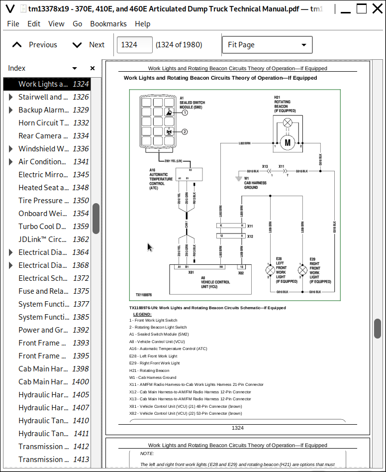
Work Lights and Rotating Beacon Circuits Theory of Operation—If Equipped
Stairwell and Service Lights Circuits Theory of Operation
Backup Alarm and Backup Lights Circuits Theory of Operation
Horn Circuit Theory of Operation
Rear Camera Circuit Theory of Operation—If Equipped
Windshield Wipers and Washers Circuits Theory of Operation
Air Conditioner and Heater Circuits Theory of Operation
Electric Mirror Circuit Theory of Operation—If Equipped
Heated Seat and Air Seat Compressor Circuits Theory of Operation
Tire Pressure Monitoring (TPM) System Theory of Operation—If Equipped
Onboard Weighing (OBW) Circuit Theory of Operation—If Equipped
Turbo Cool Down and Auto Engine Shutdown Circuits Theory of Operation
JDLink™ Circuit Theory of Operation—If Equipped
Group 10: System Diagrams
Electrical Diagram Information
Electrical Schematic Symbols
Fuse and Relay Specifications
System Functional Schematic, Component Location, and Wiring Diagram Master Legend
System Functional Schematic
Power and Ground (W10) Component Location
Front Frame Harness (W11) Component Location
Front Frame Harness (W11) Wiring Diagram
Cab Main Harness (W12) Component Location
Cab Main Harness (W12) Wiring Diagram
Hydraulic Harness (W13) Component Location
Hydraulic Harness (W13) Wiring Diagram
Hydraulic Tank Harness (W14) Component Location
Hydraulic Tank Harness (W14) Wiring Diagram
Transmission Control Harness (W15) Component Location
Transmission Control Harness (W15) Wiring Diagram
Clutch Control Harness (W16) Component Location
Clutch Control Harness (W16) Wiring Diagram
Retarder Control Harness (W17) Component Location
Retarder Control Harness (W17) Wiring Diagram
Transmission Output Speed Sensor Harness (W18) Component Location
Transmission Output Speed Sensor Harness (W18) Wiring Diagram
Articulation Harness (W19) Component Location
Articulation Harness (W19) Wiring Diagram
Rear Frame Harness (W20) Component Location
Rear Frame Harness (W20) Wiring Diagram
Rear Lights Harness (W21) Component Location
Rear Lights Harness (W21) Wiring Diagram
Cab Work Lights Harness (W22) Component Location—If Equipped
Cab Work Lights Harness (W22) Wiring Diagram—If Equipped
AM/FM Radio Harness (W23) Component Location
AM/FM Radio Harness (W23) Wiring Diagram
Automatic Temperature Control Sensors Harness (W24) Component Location
Automatic Temperature Control (ATC) Sensors Harness (W24) Wiring Diagram
Engine Harness (W25) Component Location
Engine Harness (W25) Wiring Diagram
Engine Interface Harness (W26) Component Location
Engine Interface Harness (W26) Wiring Diagram
Engine Oil Pressure Sensor Harness (W27) Component Location
Engine Oil Pressure Sensor Harness (W27) Wiring Diagram
Engine Crankshaft Sensor Harness (W28) Component Location
Engine Crankshaft Sensor Harness (W28) Wiring Diagram
Low-Pressure Fuel System (LPFS) Harness (W29) Component Location
Low-Pressure Fuel System (LPFS) Harness (W29) Wiring Diagram
Exhaust Aftertreatment Harness (W30) Component Location
Exhaust Aftertreatment Harness (W30) Wiring Diagram
Diesel Fired Coolant Heater (DFCH) Harnesses (W31 and W32) Component Location—If Equipped
Diesel Fired Coolant Heater (DFCH) Harness (W31) Wiring Diagram—If Equipped
Diesel Fired Coolant Heater (DFCH) Control Harness (W32) Wiring Diagram—If Equipped
Rear View Camera Harnesses (W33, W34, and W35) Component Location—If Equipped
Rear View Camera Harnesses (W33, W34, and W35) Wiring Diagram—If Equipped
Service Brake Pressure Sensors Harness (W37) Component Location
Service Brake Pressure Sensors Harness (W37) Wiring Diagram
Left and Right Onboard Weighing (OBW) Strain Gauge Harnesses (W45 and W46) Component Location—If Equipped
Left and Right Onboard Weighing (OBW) Strain Gauge Harnesses (W45 and W46) Wiring Diagram—If Equipped
JDLink™ Harnesses (W6002 and W6003) Component Location—If Equipped
JDLink™ Modular Telematics Gateway (MTG) Harness (W6002) Wiring Diagram—If Equipped
JDLink™ Satellite (SAT) Harness (W6003) Wiring Diagram—If Equipped
Group 15: Diagnostic Information
Electrical Component Specifications
Onboard Weighing (OBW) Does Not Function Properly
Service ADVISOR™ Diagnostic Application
Service ADVISOR™ Connection Procedure
Reading Diagnostic Trouble Codes with Service ADVISOR™ Diagnostic Application
Intermittent Diagnostic Trouble Code (DTC) Diagnostics
Using Service ADVISOR™ Remote
JDLink™ Connection Procedure
TPM—SmartWave® Advanced Maintenance Tool Diagnostics
Group 16: Primary Display Unit (PDU) Operation
Accessing Service Mode
Operation—Exhaust Filter Service and Settings
Diagnostics—Clearing Codes
Diagnostics—JDLink™ System Info
Diagnostics—Software Delivery Settings
Diagnostics—Engine Sensors Readings
Diagnostics—Transmission Sensors Readings
Diagnostics—Machine Sensors Readings
Diagnostics—ATC Readings
Setup—Monitor Menu Access
Setup—Cooling Fan Adjustment
Setup—Tire Pressure Setup
Setup—Machine Options
Setup—Owner Settings
Setup—Calibrations
Setup—Factory Default Settings
Group 17: Diagnostic Test Box
Setup and Functional Test
Two Wire Sensor Circuit Check—Out of Range High
Two Wire Sensor Circuit Check—Out of Range Low
Three Wire Sensor Circuit Check—Out of Range High
Three Wire Sensor Circuit Check—Out of Range Low
Group 20: Adjustments
Vehicle Control Unit (VCU) Outputs
Strut Position Sensor Linkage Adjustment
Dump Body Position Sensor Adjustment
Dump Body Position Sensor Calibration
Slope Sensor Calibration
Onboard Weighing (OBW) Calibration—If Equipped
TPM—Activating Tire Pressure Monitoring System
TPM—Programming Sensors With SmartWave® Advanced Maintenance Tool
TPM—Programming Using Sensor Identification Numbers
TPM—Cold Inflation Pressure (CIP) Setup
TPM—Alarm Setup
TPM—Delete Sensors
Group 25: Tests
Alternator Test
Relay Test
Diode Test
Controller Area Network (CAN) Circuit Test
Controller Area Network (CAN) Resistor Test
Hydraulic Pressure Sensors Test
Hydraulic Temperature Sensors Test
Steering Column Multi-Function Switch Test
Transmission Solenoids and Sensors Tests
Section 9020: Power Train
Group 05: Theory of Operation
Transmission Control System
Transmission Cross Sectional Diagram
Transmission System Schematic
Torque Converter Operation
Transmission Clutch Engagement
Transmission Retarder Operation
Transmission Inter-Axle Differential Lock (IDL) Operation
Axle Operation
Cross-Axle Differential Lock (CDL) Operation
Service Brake System Operation
Park Brake Operation
Suspension System Operation
Group 10: System Diagrams
Transmission External Components
Power Train Component Location
Service Brake Circuit Component Location
Group 15: Diagnostic Information
Axle Oil Leaking
Axle Assembly Noisy
Axle Oil Overheating
Cross-Axle Differential Lock (CDL) Does Not Work
Inter-Axle Differential Lock (IDL) Does Not Work
Auto Differential Lock (ADL) Does Not Work
Service Brake Excessive Wear
Poor or No Service Brake
Time Between Service Brake Accumulator Charging Cycles Too Short
Service Brake Noise and Vibration
Service Brakes Do Not Fully Release
Park Brake Does Not Release
Park Brake Will Not Hold
Machine Will Not Move
Transmission Will Not Shift to Forward or Reverse
Machine Creeps in Neutral
Engine Speed Too High During Torque Converter Stall
Engine Speed Too Low During Torque Converter Stall
Excessive Clutch Slippage and Chatter
Oil Comes Out of Transmission Oil Fill Tube
Buzzing Noise From Transmission
Transmission Overheating in all Gears
Transmission Not Shifting Properly (Rough Shifts, Shifting at Too-Low or Too-High Speed)
Transmission Will Not Make a Specific Shift
Transmission Retarder Does Not Function
Transmission Retarder Weak
Retarder Stays on When Not Requested
Transmission Retarder Too Aggressive
Group 25: Tests
Transmission Warm-Up Procedure
JT02156A Digital Pressure/Temperature Analyzer Installation
Transmission Pressure Test
Transmission Clutch Drag Test
Transmission Pump Flow Test
Transmission Oil Cooler Restriction Test
Transmission Oil Cooler Thermal Bypass Valve Temperature Test
Transmission Oil Cooler Thermal Bypass Valve Pressure Test
Torque Converter—Inlet Pressure Test
Torque Converter—Inlet Flow Test and Relief Pressure Test
Torque Converter Stall Test
Torque Converter Stator Tests
Torque Converter Lockup Test
Electronic Clutch Calibration
Service Brake Accumulator Pressure Regulator Valve Test and Adjustment
Service Brake Accumulator Charge Valve Test and Adjustment
Service Brake Accumulator Pressure Sensor and Service Brake Accumulator Charge Test
Front and Rear Service Brake Accumulators Pressure Test and Charge Procedure
Service Brake Inspection
Service Brake Valve Test
Electronic Brake Valve (EBV) Test
Axle Cooling Pump and Axle Lubrication Pressure Test
Axle Cooling Pump Flow Test
Park Brake Test
Park Brake Pressure Test
Park Brake Pad Thickness Check
Park Brake Adjustment
Strut Accumulator Pressure Test and Charge Procedure
Cross-Axle Differential Lock (CDL) Pressure Test
Inter-Axle Differential Lock (IDL) Pressure Test
Middle and Rear Axle Oil Sampling Procedure
Section 9025: Hydraulic System
Group 05: Theory of Operation
Hydraulic System Operation
Main Hydraulic Pump Operation
Main Hydraulic Pump Load Sense Operation
Service Brake System Operation
Steering and Secondary Steering System Operation
Steering Valve Operation
Secondary Steering Pump Operation
Hydraulic System Manifold Operation
Fan Drive System Operation
Group 10: System Diagrams
Hydraulic System Schematic
Hydraulic System Component Location
Group 15: Diagnostic Information
No Hydraulic Functions
All Hydraulic Functions Slow
Hydraulic Oil Overheats
Main Hydraulic Pump Noisy
Dump Body Will Not Rise
Hydraulic Fan Motor Not Working
Hydraulic Fan Runs at Full Speed
Poor or No Service Brakes
Service Brake Pads Excessive Wear
Time Between Service Brake Accumulator Charging Cycles Too Short
Service Brake Overheats
Service Brake Cooling Oil Leaking
Service Brake Noise and Vibration
Service Brakes Do Not Fully Release
Slow or No Steering Function
Constant Steering Needed to Maintain Straight Travel
Steering Erratic
Steering Soft or Spongy
Steering Wheel Free Play
Steering Locks Up
Steering Wheel Turns by Itself
Machine Turns in Opposite Direction as Steering Wheel
Machine Turns With Steering Valve in Neutral
Suspension System Not Working
Group 25: Test
JT02156A Digital Pressure/Temperature Analyzer Installation
Hydraulic System Warm-Up Procedure
Cycle Time Test
Main Hydraulic Pump Margin and Maximum Pressure Test and Adjustment
Dump Body Pilot Pressure Test and Adjustment
Dump Body Manual Lowering and Bin Tip Circuit Pressure Relieving Procedure
Priority Valve Test
Service Brake Accumulator Pressure Regulator Valve Test and Adjustment
Service Brake Accumulator Charge Valve Test and Adjustment
Service Brake Accumulator Pressure Sensor and Service Brake Accumulator Charge Test Procedure
Front and Rear Service Brake Accumulators Pressure Test Procedure
Service Brake Valve Test Procedure
Electronic Brake Valve (EBV) Test Procedure
Axle Cooling Pump Pressure, Lubrication, and Flow Test
Steering Valve Leakage Test
Steering Relief Valve Pressure Test and Adjustment
Steering Cylinder Leakage Test
Hydraulic Fan Circuit Flow Test
Section 9031: Heating and Air Conditioning
Group 05: Theory of Operation
Air Conditioning System Cycle of Operation
Group 15: Diagnostic Information
Air Conditioning System Does Not Operate
Air Conditioning System Does Not Cool Interior of Cab
Air Conditioning System Runs Constantly, Too Cold
Interior Windows Continue to Fog
Heating System Does Not Operate
Heating System Does Not Warm Interior of Cab
Group 25: Tests
R134a Refrigerant Cautions and Proper Handling
Heater and Air Conditioner Operational Checks
Air Conditioning System Test
Operating Pressure Diagnostic Chart
Air Conditioner Freeze Control Sensor Test
Air Conditioner Compressor Clutch Test
Air Conditioner High/Low-Pressure Switch Test
R134a Refrigerant Leak Test
R134a Oil Charge Capacity
R134a Refrigerant Charge Capacity
R134a Refrigerant Hoses and Tubing Inspection
John Deere Articulated Dump Trucks 370E, 410E, 460E Operation and Test Service Manual (TM13378X19)
![]()