
John Deere 250D and 300D Articulated Dump Truck Service Manual - TM2115 (Operation & Test)
John Deere 250D and 300D Articulated Dump Truck Service Manual - TM2115 (Operation & Test)
TM2115 - John Deere 250D and 300D Articulated Dump Truck BELL—(200537-201811) Tier 2 Technical Manual - Operation & Test.pdf
Complete technical manual (Operation & Test) with Electrical Wiring Diagrams for John Deere 250D and 300D Articulated Dump Truck BELL—(200537-201811) Tier 2 Articulated Dump Truck BELL—(200537-201811) Tier 2, with all the shop information to maintain, diagnostic, repair, refurbishrebuild like professional mechanics.
John Deere 250D and 300D Articulated Dump Truck (ADT) BELL—(200537-201811) Tier 2 workshop service & repair manual includes:
* Numbered table of contents easy to use so that you can find the information you need fast.
* Detailed sub-steps expand on repair procedure information
* Numbered instructions guide you through every repair procedure step by step.
* Troubleshooting and electrical service procedures are combined with detailed wiring diagrams for ease of use.
* Notes, cautions and warnings throughout each chapter pinpoint critical information.
* Bold figure number help you quickly match illustrations with instructions.
* Detailed illustrations, drawings and photos guide you through every procedure.
* Enlarged inset helps you identify and examine parts in detail.
MAIN SECTIONS
Forword
9900 - Dealer Fabricated Tools
9000 - General Information
9020 - Power Train
9022 - Pneumatic System
9025 - Hydraulic System
9031 - Heating and Air Conditioning
9005 - Operational Checkout Procedure
9010 - Engine
9015 - Electrical System
Total Pages: 601 pages
File Format: PDF (bookmarked, Searchable, Printable, high quality)
Language: English
tm2115 - 250D and 300D Articulated Dump Truck (BELL - S.N. 200537—201811) (DW - S.N. 599286—609165)
Table of Contents
Foreword
Technical Information Feedback Form
Section 9000: General Information
Group 01: Safety
Recognize Safety Information
Follow Safety Instructions
Operate Only If Qualified
Wear Protective Equipment
Avoid Unauthorized Machine Modifications
Inspect Machine
Stay Clear of Moving Parts
Avoid High-Pressure Oils
Beware of Exhaust Fumes
Prevent Fires
Prevent Battery Explosions
Handle Chemical Products Safely
Dispose of Waste Properly
Prepare for Emergencies
Use Steps and Handholds Correctly
Start Only From Operator's Seat
Use and Maintain Seat Belt
Prevent Unintended Machine Movement
Avoid Work Site Hazards
Keep Riders Off Machine
Avoid Backover Accidents
Avoid Machine Tip Over
Operating on Slopes
Operating Or Traveling On Public Roads
Inspect and Maintain ROPS
Add and Operate Attachments Safely
Park And Prepare For Service Safely
Service Tires Safely
Service Cooling System Safely
Remove Paint Before Welding or Heating
Make Welding Repairs Safely
Drive Metal Pins Safely
Section 9005: Operational Checkout Procedure
Group 10: Operational Checkout Procedure
Operational Checkout
Section 9010: Engine
Group 05: Theory of Operation
John Deere 6081 8.1 L Engine
Group 15: Diagnose Engine Malfunctions
Diagnose Engine Malfunctions
Group 20: Adjustments
Display Monitor Tachometer
Slow and Fast Idle Adjustment
Group 25: Tests
Air Intake System Leakage Test
Section 9015: Electrical System
Group 05: System Information
Electrical Diagram Information
Group 10: System Diagrams
Explanation of Wire Markings
Fuse Specifications
Functional Schematic Section Legend
Functional Schematic and Component Location Legend (S.N. 200537—200926)
Functional Schematic and Component Location Legend (S.N. 200927—)
Electrical System Functional Schematic (S.N. 200537—200926)
Electrical System Functional Schematic (S.N. 200927—)
Main Power Harness (W6) Component Location (S.N. 200537—200926)
Main Power Harness (W6) Component Location (S.N. 200927— )
Main Power Harness (W6) Wiring Diagram (S.N. 200537—200926)
Main Power Harness (W6) Wiring Diagram (S.N. 200927—)
Front Frame/Engine Harness (W7) Component Location (S.N. 200537—200926)
Front Frame/Engine Harness (W7) Component Location (S.N. 200927— )
Front Frame/Engine Harness (W7) Wiring Diagram (S.N. 200537—200926)
Front Frame/Engine Harness (W7) Wiring Diagram (S.N. 200927—)
Cab Main Harness (W10) and Electric Mirror Interface Harness (W17) Component Location
Cab Main Harness (W10) and Electric Mirror Interface Harness (W17) Wiring Diagram (S.N. 200537—200926)
Cab Main Harness (W10) and Electric Mirror Interface Harness (W17) Wiring Diagram (S.N. 200927—)
Transmission Control Module Harness (W11) Component Location
Transmission Control Module Harness (W11) Wiring Diagram (S.N. 200537—200926)
Transmission Control Module Harness (W11) Wiring Diagram (S.N. 200927—)
Transmission Control Harness (W12) Component Location
Transmission Control Harness (W12) Wiring Diagram (S.N. 200537—200926)
Transmission Control Harness (W12) Wiring Diagram (S.N. 200927—)
Transmission Harness (W13) Component Location
Transmission Harness (W13) Wiring Diagram (S.N. 200537—200926)
Transmission Harness (W13) Wiring Diagram (S.N. 200927—)
Hydraulic Harness (W14) Component Location
Hydraulic Harness (W14) Wiring Diagram (S.N. 200537—200926)
Hydraulic Harness (W14) Wiring Diagram (S.N. 200927—)
Rear Frame Harness (W15) Component Location
Rear Frame Harness (W15) Wiring Diagram (S.N. 200537—200926)
Rear Frame Harness (W15) Wiring Diagram (S.N. 200927—)
Work Light Harness (W16) Component Location
Work Light Harness (W16) Wiring Diagram (S.N. 200537—200926)
Work Light Harness (W16) Wiring Diagram (S.N. 200927—)
Air Conditioning Actuator Harness (W18) Component Location
Air Conditioning Actuator Harness (W18) Wiring Diagram (S.N. 200537—200926)
Air Conditioning Actuator Harness (W18) Wiring Diagram (S.N. 200927—)
Group 15: Sub-System Diagnostics
Starting and Charging Circuit Theory of Operation
Engine Control Unit and Electronic Fuel Injection Control Circuit Theory of Operation
Transmission Control Unit and Retarder Circuit Theory of Operation
Chassis Control Unit Circuit Theory of Operation
Dump Body Control and Range Hold Circuit Theory of Operation
Park Brake Circuit Theory of Operation
Monitor Display Unit Circuit Theory of Operation
Turn Signal and 4-Way Flasher Circuit Theory of Operation
Stop Light Circuit Theory of Operation
Backup Alarm and Backup Light Circuit Theory of Operation
Wiper/Washer Circuit Theory of Operation
Battery Balancer and 12-Volt Accessory Circuit Theory of Operation
Air Conditioning Circuit Theory of Operation
Electric Mirror Circuit Theory of Operation
Unloader Valve Heater Circuit Theory of Operation
Group 20: References
Diagnostic Trouble Codes—After Machine Repair
Diagnostic Trouble Codes—How Codes Are Displayed On Monitor Display Unit
Diagnostic Trouble Codes Quick Reference List
Diagnostic Trouble Codes—Engine Control Unit
Diagnostic Trouble Codes—Chassis Control Unit
Diagnostic Trouble Codes—Transmission Control Unit
Diagnostic Trouble Codes—Transmission Control Unit (Continued)
Check Controller
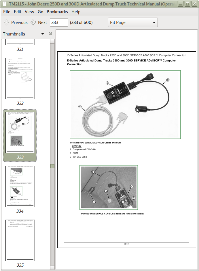
D-Series Articulated Dump Trucks 250D and 300D SERVICE ADVISOR SERVICE ADVISOR is a trademark of Deere & Company Computer Connection
Two-Wire Sensor Circuit Check Using Monitor Display Unit (MDU) or SERVICE ADVISOR SERVICE ADVISOR is a trademark of Deere & Company
Three-Wire Sensor Circuit Check Using Monitor Display Unit (MDU) or SERVICE ADVISOR SERVICE ADVISOR is a trademark of Deere & Company
Key Switch Test
Relay Test
Diode Test
CAN Circuit Testing
Pneumatic System Solenoids, Pressure Switches, and Sensor Tests
Hydraulic Pressure Switches Test
Hydraulic Temperature Sensors Test
Body Position Sensor Test
Steering Column Switch Test
Transmission Solenoids, Speed Sensors, Sump Temperature Sensor, and Retarder Resistor Tests
Retarder Proportional Solenoid Test
Retarder Temperature Sensor Test
Transmission Shift Control Test
Remove and Install Engine Control Unit
Remove and Install Chassis Control Unit
Remove and Install Transmission Control Unit
Remove and Install Battery Balancer
Program Monitor Display Unit (MDU)
Monitor Display Unit Remove and Install
Replace Monitor Display Unit Bulbs
Replace DEUTSCH DEUTSCH is a trademark of Deutsch Co. Rectangular or Triangular Connectors
Replace DEUTSCH DEUTSCH is a trademark of the Deutsch Co. Connectors
Install DEUTSCH DEUTSCH is a trademark of the Deutsch Co. Contact
Replace WEATHER PACK WEATHER PACK is a trademark of Packard Electric. Connector
Install WEATHER PACK WEATHER PACK is a trademark of Packard Electric. Contact
Replace (Pull Type) Metri-Pack™ Connectors
Replace (Push Type) Metri-Pack™ Connectors
Remove Connector Body from Blade Terminals
Section 9020: Power Train
Group 05: Theory of Operation
Transmission External Components
Transmission Control System
Transmission Cross Sectional Diagram
Torque Converter Operation
Transmission Clutch Engagement
Transmission Retarder Operation
Transfer Case and Inter-Axle Differential Lock (IDL) Operation
Group 15: Diagnostic Information
Diagnostic Procedure
Diagnose Power Train System Malfunctions
Power Train Component Location Diagram
Group 25: Tests
Transmission Warm-Up Procedure
Transmission Pressure Test
Torque Converter Stall Test
Torque Converter Stator Tests
Transmission Oil-to-Air Cooler Restriction Test
Transmission Oil-to-Water Cooler Restriction Test
Front Suspension Strut Leakage Check
Front Axle Suspension Strut Height Check
Park Brake Test
Park Brake Pad Thickness Check
Park Brake Adjustment
Wheel Hub Bearing Preload Adjustment (Wheel Installed)
Section 9022: Pneumatic System
Group 05: Theory of Operation
Pneumatic System Schematic
Pneumatic System Operation
Air Pressure Supply Circuit Operation
Air Dryer and Unloader Valve
Pneumatic Manifold
Pneumatic Circuit
Group 15: Diagnostic Information
Diagnostic Procedure
Diagnose Pneumatic System Malfunctions
Pneumatic System Component Location Diagram
Group 25: Tests
Pneumatic System Main Pressure Test and Adjustment
Park Brake Pressure Test
Section 9025: Hydraulic System
Group 05: Theory of Operation
Articulated Dump Truck Hydraulic System Operation
Main Hydraulic Pump Operation
Main Hydraulic Pump Load Sense Operation
Service Brake System Operation
Steering and Secondary Steering System Operation
Steering Valve Operation
Secondary Steering Pump Operation
Hydraulic System Manifold Operation
Dump Body Control Valve Operation
Hydraulic System Circuit Symbols
Hydraulic System Schematic
Group 15: Diagnostic Information
Diagnostic Procedure
Diagnose Hydraulic System Malfunctions
Diagnose Service Brake System Malfunctions
Diagnose Steering System Malfunctions
Hydraulic System Component Location
Group 25: Tests
JT05800 Digital Thermometer Installation
JT02156A Digital Pressure/Temperature Analyzer Installation
Hydraulic Oil Cleanup Procedure Using Portable Filter Caddy
Hydraulic System Warm-Up Procedure
Cycle Time Test
Main Hydraulic Pump Residual and Compensator Valves Test and Adjustment
System Relief Valve and Dump Body Raise Circuit Relief Valve Test
Priority Valve Test
Accumulator Pressure Reducing Valve Test and Adjustment
Brake Accumulator Charge Valve Test and Adjustment
Brake Low Pressure Switch and Brake Charge Accumulator Test
Front and Rear Brake Apply Accumulators Pressure Test and Charge Procedure
Service Brake Valve Test
Steering Relief Valve Pressure Test and Adjustment
Steering Cylinder Leakage Test
Secondary Steering Pump Residual and Compensator Valves Test and Adjustment
Dump Body Lower Circuit Relief Valve Test
Section 9031: Heating and Air Conditioning
Group 05: Theory of Operation
Air Conditioning System Cycle of Operation
Heater Core Operation
Group 15: Diagnostic Information
Diagnose Air Conditioning System Malfunctions
Diagnose Heater System Malfunctions
Heating/Air Conditioning Component Location
Group 25: Tests
Air Conditioning System Inspection
R134a Air Conditioning System Test
Operating Pressure Diagnostic Chart
A/C Freeze Control Switch Test
A/C Compressor Clutch Test
A/C High/Low Pressure Switch Test
Expansion Valve Operating Test
Refrigerant Leak Test
![]()