
John Deere 570B Motor Grader Service Repair Manual (TM1400)
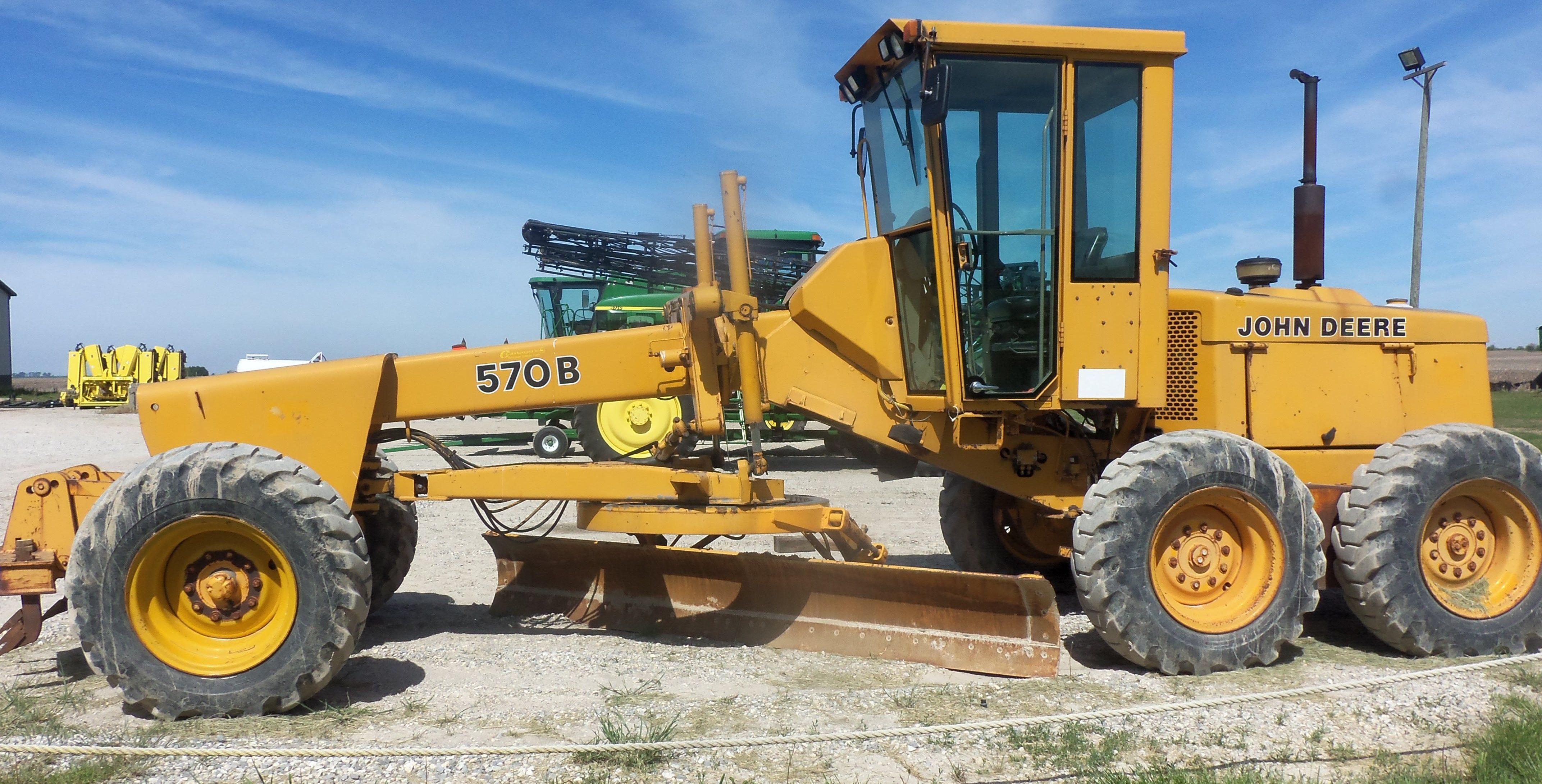

John Deere 570B Motor Grader Service Repair Manual (TM1400)
TM1400 - John Deere 570B Motor Grader Technical Manual - Repair.pdf
Complete repair service technical manual for John Deere 570B Motor Grader, with all the service information to maintain, diagnose, repair, rebuild like professional mechanics.
John Deere 570B Grader workshop service repair manual includes:
* Numbered table of contents easy to use so that you can find the information you need fast.
* Detailed sub-steps expand on repair procedure information
* Numbered instructions guide you through every repair procedure step by step.
* Notes, cautions and warnings throughout each chapter pinpoint critical information.
* Bold figure number help you quickly match illustrations with instructions.
* Detailed illustrations, drawings and photos guide you through every procedure.
* Enlarged inset helps you identify and examine parts in detail.
PRODUCT DETAILS:
Total Pages: 774 pages
File Format: PDF (bookmarked, Searchable, Printable, high quality PDF)
Language: English
MAIN SECTIONS
Foreword
General Information
Safety
General Specifications
Torque Values
Fuels And Lubrication
Wheels And Fastenings
Wheels
Axles And Suspension Systems
Front Axle And Wheel Hubs
Axle Shaft, Bearings And Reduction Gears
Hydraulic System
Transmission
Removal And Installation
Control Linkage
Gears, Shafts, Bearings And Power Shift Clutch
Hydraulic System
Engine
Removal And Installation
Engine Auxiliary System
Cold Weather Starting Aids
Cooling System
Speed Controls
Intake System
External Fuel Supply Systems
Dampener Drive
Control Linkage
Elements
Transfer Drive
Removal And Installation
Gears, Shafts And Bearings
Steering System
Power Steering
Hydraulic System
Service Brakes
Active Elements
Control Linkage
Hydraulic System
Park Brake
Active Elements
Controls Linkage
Electrical System
Batteries
Alternator, Regulator And Charging System Wiring
Wiring Harness And Switches
Motors And Actuators
Frames
Frame Installation
Operator’s Station
Removal And Installation
Operator Enclosure
Seat And Seat Belt
Heating And Air Conditioning
Main Hydraulic System
Hydraulic System
Grading Device
Controls Linkage
Frames
Circle Gearbox
Hydraulic System
Ground Conditioning Tool
Frames
Hydraulic System
Dealer Fabricated Tools
tm1400 - 570B Motor Grader Repair
Table of Contents
Foreword
Section I: General Information
Group I: Safety
Handle Fluids Safely-Avoid Fires
Prevent Battery Explosions
Prepare for Emergencies
Prevent Acid Burns
Handle Chemical Products Safely
Avoid High-Pressure Fluids
Park Machine Safely
Support Machine Properly
Wear Protective Clothing
Work in Clean Area
Service Machines Safely
Work In Ventilated Area
Illuminate Work Area Safely
Replace Safety Signs
Use Proper Lifting Equipment
Remove Paint Before Welding or Heating
Avoid Heating Near Pressurized Fluid Lines
Keep ROPS Installed Properly
Service Tires Safely
Avoid Harmful Asbestos Dust
Practice Safe Maintenance
Use Proper Tools
Dispose of Waste Properly
Live With Safety
Group II: General Specifications
570B Specifications
Group III: Torque Values
Hardware Torque Specifications
Metric Bolt and Cap Screw Torque Values
Additional Metric Cap Screw Torque Values
Unified Inch Bolt and Cap Screw Torque Values
Check Oil Lines And Fittings
Service Recommendations for O-Ring Boss Fittings
Service Recommendations for Flat Face O-Ring Seal Fittings
Service Recommendations for Metric Series Four Bolt Flange Fitting
Service Recommendations For Inch Series Four Bolt Flange Fittings
Group IV: Fuels And Lubrication
Fuel Specifications
Low Sulfur Diesel Fuel Conditioner
Storing Fuel
Do Not Use Galvanized Containers
Fuel Tank
Engine Oil
Transmission, Hydraulic System, Tandem Drive, And Wheel Motor Oil
Circle Drive Gearbox Oil
Grease
Alternative and Synthetic Lubricants
Lubricant Storage
Mixing of Lubricants
Diesel Engine Coolant
Section 01: Wheels And Fastenings
Group 0110: Wheels
Specifications
Remove And Install Rim Assembly (Multiple Section Rim)
Remove And Install Rim Assembly (One Piece Rim)
Remove Tire
Install Tire
Remove Tire (One Piece Rim)
Install Tire (One Piece Rim)
Section 02: Axles And Suspension Systems
Group 0230: Front Axle And Wheel Hubs
Specifications
Remove And Install Front Wheel Hub And Spindle
Disassemble And Assemble Front Wheel Hub
Remove And Install Front Axle Assembly
Group 0250: Axle Shaft, Bearings And Reduction Gears
Essential Tools
Service Equipment And Tools
Other Material
Specifications
Cross Section View Of Final Drive And Tandem Assembly
Inspect Drive Chain Wear
Remove And Install Drive Chain
Remove And Install Wheel Axle And Housing Assembly
Disassemble And Assemble Driven Axle
Adjust Rolling Drag Torque
Remove And Install Power Unit
Remove And Install Tandem And Axle Assembly
Remove And Install Tandem Drive Sprocket
Disassemble And Assemble Pivot Housing
Remove And Install Final Drive
Disassemble And Assemble Final Drive
Group 0260: Hydraulic System
Specifications
Disassemble And Assemble Differential Lock Control Valve (S.N. -538882)
Remove And Install Differential Lock Solenoid Valve (S.N. 538883)
Section 03: Transmission
Group 0300: Removal And Installation
Essential Tools
Specifications
Remove Transmission
Install Transmission
Group 0315: Control Linkage
Other Material
Specifications
Disassemble And Assemble Transmission Control Lever Housing And Shift Control Cable
Disassemble And Assemble Transmission Gear Shift Lever And Linkage
Remove, Install And Adjust Direction Control Cable
Remove, Install And Adjust Gear Selector Control Cable
Check Shift Control Adjustment
Group 0350: Gears, Shafts, Bearings And Power Shift Clutch
Special Or Essential Tools
Service Equipment And Tools
Other Material
Specifications
Remove Differential
Remove And Install Ring Gear
Disassemble And Assemble Differential
Test And Adjust Differential
Install Differential
Adjust Differential Bearing Preload
Adjust Differential Backlash
Final Assembly Of Differential
Disassemble Differential Drive Shaft
Adjust Cone Point
Example For Finding Cone Point Shim Pack
Assemble Differential Drive Shaft
Measure Differential Drive Shaft End Play
Check Rolling Drag Torque
Remove Clutch Housing
Disassemble And Assemble Hi-Lo Clutch Range Shaft
Install Clutch Housing
Remove Clutch Pack
Disassemble Clutch Pack And Oil Manifold
Disassemble C2 High-Range Clutch Pack
Disassemble Low-Range Clutch
Disassemble Manifold And Oil Pump
Assemble Oil Manifold And Clutch Pack
Hi-Lo Clutch And Oil Manifold Assembly Air Test
Remove Planetary Pack
Disassemble Planetary Pack
Disassemble And Assemble C3 Planetary Clutch
Disassemble And Assemble Planetary Carrier
Assemble Planetary Carrier
Assemble Planetary Pack
Planetary Pack Air Test
Install Planetary Pack
Disassemble And Assemble Planetary And Clutch Support With Hi-Lo Shaft
Remove Reduction Gear Shaft
Adjust Reduction Gear Shaft Preload
Install Reduction Gear Shaft
Disassemble And Assemble Tow Disconnect
Adjust Tow Disconnect
Group 0360: Hydraulic System
Specifications
Remove And Install Transmission Control Valve Assembly
Disassemble And Assemble Transmission Control Valve
Disassemble And Assemble Shift Valve
Disassemble And Assemble Interrupter Valve
Disassemble And Assemble Control Valve Cover
Disassemble B1-B2 And B3-B4-C3 Accumulators
Assemble B1-B2 And B3-B4-C3 Accumulators
Remove Transmission Clutch And Pressure Regulating Valve Housing
Disassemble Transmission Clutch Valve
Assemble Transmission Clutch Valve
Disassemble And Assemble Pressure Regulating Valve
Install Clutch Valve Housing And Pressure Regulating Valve Housings
Disassemble And Assemble Transmission Suction Filter
Section 04: Engine
Group 0400: Removal And Installation
6359 John Deere Engine Repair-Use CTM4 (S.N. -543489)
6059 John Deere Engine Repair-Use CTM8 (S.N. 543490-)
John Deere OEM Engine Accessories-Use CTM67
John Deere Alternators And Starting Motors-Use CTM77
Special Or Essential Tools
Service Equipment And Tools
Specifications
Disconnect Turbocharger Oil Inlet Line
Remove And Install Engine
Remove And Install Oil Pan
Remove Injection Pump
Repair Fuel Injection Pump
Install Injection Pump
Remove Injection Pump Drive Shaft
Install Injection Pump Drive Shaft
Remove Injection Nozzles
Install Injection Nozzle
Bleed Fuel System
Remove Turbocharger
Install Turbocharger
Remove And Install Water Pump
Section 05: Engine Auxiliary System
Group 0505: Cold Weather Starting Aids
Other Material
Specifications
Remove And Install Starting Aid Solenoid And Nozzle
Remove And Install Engine Coolant Heater
Group 0510: Cooling System
Other Material
Specifications
Remove And Install Fan
Remove And Install Radiator
Remove And Install Fan Belts
Group 0515: Speed Controls
Other Material
Specifications
Remove And Install Speed Control Assembly
Speed Control Linkage Adjustment
Group 0520: Intake System
Remove And Install Air Cleaner
Group 0560: External Fuel Supply Systems
Remove And Install Fuel Tank
Section 07: Dampener Drive
Group 0715: Control Linkage
Disassemble And Assemble Clutch Pedal And Linkage
Adjust Clutch Valve Linkage
Group 0752: Elements
Special Or Essential Tools
Other Material
Specifications
Remove And Install Dampener-Early Machines
Remove And Install Dampener-Later Machines
Section 08: Transfer Drive
Group 0800: Removal And Installation
Service Equipment And Tools
Other Material
Remove Transfer Drive Assembly
Install Transfer Drive Assembly
Group 0851: Gears, Shafts And Bearings
Specifications
Other Material
Service Equipment And Tools
Transfer Drive Assembly
Disassemble And Assemble Input Gear Assembly
Disassemble And Assemble Upper And Lower Idler Assemblies
Adjust Idler Gear End Play
Disassemble And Assemble Output Gear Assembly
Section 09: Steering System
Group 0920: Power Steering
Specifications
Remove And Install Bellcrank Assembly
Check And Adjust Toe-In
Group 0960: Hydraulic System
Special Or Essential Tools
Service Equipment And Tools
Other Material
Specifications
Disassemble Steering Valve
Assemble Steering Valve
Remove And Install Steering Wheel, Column, And Valve
Disassemble And Assemble Front Steer Cylinder
Remove Lean Wheel Cylinder
Disassemble And Assemble Rear Steer Cylinder (S.N. -540254)
Disassemble And Assemble Rear Steer Cylinder (S.N. 540255-)
Remove And Install Counterbalance Valve
Section 10: Service Brakes
Group 1011: Active Elements
Other Material
Disassemble And Assemble Brake Elements
Inspect Service Brakes
Group 1015: Control Linkage
Disassemble And Assemble Brake Pedal (S.N. -543489)
Group 1060: Hydraulic System
Specifications
Disassemble And Assemble Brake Valve (S.N. -543489)
Remove And Install Brake Valve (S.N. 543490-)
Disassemble And Assemble Brake Valve (S.N. 543490-)
Bleed Brake Hydraulic System
Remove And Install Brake Accumulator
Disassemble And Assemble Brake Accumulator (S.N. -543489)
Charge Brake Accumulator (S.N. -543489)
Remove And Install Brake Accumulator (S.N. 543490-)
Charge Brake Accumulator (S.N. 543490-)
Section 11: Park Brake
Group 1111: Active Elements
Other Material
Specifications
Cross Section Of Park Brake
Disassemble And Assemble Brake Drum
Remove And Disassemble Park Brake Pinion Shaft
Assemble Pinion Shaft
Install Pinion Shaft
Group 1115: Controls Linkage
Disassemble And Assemble Park Brake Linkage
Adjust Park Brake
Section 16: Electrical System
Group 1671: Batteries
Specifications
Avoid Battery Acid
Battery State Of Charge
Using Booster Batteries-24-Volt System
Charge Battery
Group 1672: Alternator, Regulator And Charging System Wiring
Alternators And Starting Motors-Use CTM77
Service Equipment And Tools
Specifications
Remove And Install Alternator
Group 1674: Wiring Harness And Switches
Special Or Essential Tools
Replace Fuses (S.N. -543489)
Replace Fuses (S.N. 543490-)
Remove Blade Terminals From Fuse Block
Remove And Install Rear Steering Sensor
Adjust Rear Steering Sensor
Park Brake Switch (Primary Warning Level) Adjustment
Park Brake Switch (Indicator Light) Adjustment
Service Brake Switch Adjustment
Replace DEUTSCH DEUTSCH is a trademark of the Deutsch Company. Connectors
Install DEUTSCH DEUTSCH is a trademark of the Deutsch Company. Contact
Replace WEATHER PACK WEATHER PACK is a trademark of Packard Electric. Connector
Install WEATHER PACK WEATHER PACK is a trademark of Packard Electric. Contact
Remove Connector Body From Blade Terminals
Group 1677: Motors And Actuators
Alternators And Starting Motors-Use CTM77
Special Or Essential Tools
Specifications
Remove And Install Starting Motor
Section 17: Frames
Group 1740: Frame Installation
Separate Engine And Equipment Frame
Lower Pivot Pin Adjustment
Section 18: Operator’s Station
Group 1800: Removal And Installation
Service Equipment And Tools
Other Material
Specifications
Remove And Install Cab Or Canopy And Platform
Group 1810: Operator Enclosure
Other Material
Specifications
Remove And Install Windowpanes
Remove And Install Cab Doors
Remove And Install Door Latch
Remove And Install Inside Assist Handle-Left Door
Remove And Install Windshield Washer
Remove And Install Front Windshield Wiper
Adjust Front Windshield Wiper
Adjust Lower Windshield Wiper
Remove And Install Rear Wiper
Remove And Install Defroster Fan
Group 1821: Seat And Seat Belt
Specifications
Disassemble And Assemble Suspension Seat
Disassemble And Assemble Standard Seat
Group 1830: Heating And Air Conditioning
Other Material
Remove And Install 20,000 BTU Heater
Remove And Install 40,000 BTU Heater
Remove And Install Cab Heater Hoses And Controls (S.N. -520351)
Section 21: Main Hydraulic System
Group 2160: Hydraulic System
John Deere 2000 Series Radial Piston Hydraulic Pump-Use CTM7
Other Material
Specifications
Remove And Install Hydraulic Pump And Drive Shaft
Remove And Install Differential Lock Valve Manifold (S.N. 538883-)
Remove And Install Pressure Reducing Valve
Section 34: Grading Device
Group 3415: Controls Linkage
Remove And Install Steering Support And Console Assembly
Remove And Install Steering Tilt Assembly
Remove And Install Console Tilt Linkage
Group 3440: Frames
Other Material
Specifications
Disassemble Saddle Locking Pin
Assemble Saddle Locking Pin
Remove And Install Saddle And Pivot
Adjust Circle Horizontal Clearance
Adjust Circle Vertical Clearance
Adjust Blade Retainers
Group 3450: Circle Gearbox
Specifications
Disassemble And Assemble Circle Gearbox
Group 3460: Hydraulic System
Service Equipment And Tools
Other Material
Specifications
Remove And Install Grader Control Valve
Disassemble And Assemble Grader Control Valve
Orifice Plate Location
Disassemble And Assemble Blade Lift Or Scarifier Valve Section
Disassemble And Assemble Wheel Lean, Rear Steer, Circle Side Shift, Blade Tilt, Or Blade Side Shift Valve Section
Disassemble And Assemble Circle Rotate Valve Section
Disassemble And Inspect Return Check Poppets
Disassemble And Assemble Pressure Control Valve
Disassemble And Assemble Rotate Motor (S.N. -521646)
Disassemble And Assemble Rotate Motor (S.N. 521647-)
Disassemble And Assemble Rotary Manifold
Disassemble And Assemble Saddle Locking Pin Solenoid Valve
Remove And Install Saddle Locking Pin Solenoid Valve (S.N. 538883-)
Remove And Install Blade Side Shift Cylinder
Disassemble And Assemble Blade Side Shift And Blade Tilt Cylinders-Early Machines
Disassemble And Assemble Blade Side Shift And Blade Tilt Cylinders-Later Machines
Remove And Install Blade Lift And Circle Side Shift Cylinders
Disassemble And Assemble Blade Lift Cylinder-Early Machines
Disassemble And Assemble Blade Lift Cylinder-Later Machines
Disassemble And Assemble Circle Side Shift Cylinder-Early Machines
Disassemble And Assemble Circle Side Shift Cylinders-Later Machines
Section 42: Ground Conditioning Tool
Group 4240: Frames
Remove And Install Scarifier
Group 4260: Hydraulic System
Service Equipment And Tools
Other Material
Specifications
Disassemble And Assemble Scarifier Cylinder-Early Machines
Disassemble And Assemble Scarifier Cylinder-Later Machines
Section 99: Dealer Fabricated Tools
Group 9900: Dealer Fabricated Tools
DF1015 Tandem Lifting Tool
DF1017 Axle Lift Eye
DF1045 Clutch Housing Support Stand
DF1046 Transmission Support Bar
DF1047 Torque Adapter
DF1048 Engine Support Bracket
DF1049 Transmission Case Support Stand
JT38000 Differential Lifting Tool
![]()