
John Deere Motor Graders 670C, 670CH, 672CH, 770C, 770CH, 772CH Service Repair Manual (TM1607)
Complete service repair manual for John Deere Motor Graders 670C, 670CH, 672CH, 770C, 770CH, 772CH, with all the workshop information to maintain, repair, and rebuild like professional mechanics.
John Deere Motor Graders 670C, 670CH, 672CH, 770C, 770CH, 772CH workshop service & repair manual includes:
* Numbered table of contents easy to use so that you can find the information you need fast.
* Detailed sub-steps expand on repair procedure information
* Numbered instructions guide you through every repair procedure step by step.
* Notes, cautions and warnings throughout each chapter pinpoint critical information.
* Bold figure number help you quickly match illustrations with instructions.
* Detailed illustrations, drawings and photos guide you through every procedure.
* Enlarged inset helps you identify and examine parts in detail.
TM1607 - John Deere Motor Graders 670C, 670CH, 672CH, 770C, 770CH, 772CH Technical Manual - Repair.pdf
TM1607 - John Deere Motor Graders 670C, 670CH, 672CH, 770C, 770CH, 772CH Technical Manual - Repair.epub
Total Pages: 1,204 pages
File Format: PDF/EPUB/MOBI/AZW (PC/Mac/Android/Kindle/iPhone/iPad; bookmarked, ToC, Searchable, Printable)
Language: English
MAIN SECTIONS
Foreword
General Information
Safety
General Specifications
Torque Values
Fuels and Lubricants
Wheels
Powered Wheels and Fastenings
Axles and Suspension Systems
Differential or Bevel Drive
Input Drive Shafts and U-Joints
Non-Powered Wheel Axles
Axle Shafts, Bearings, and Reduction Gears
Hydraulic System
Dealer Fabricated Tools
Transmission
Removal and Installation
Gears, Shafts, Bearings and Power Shaft Clutch
Hydraulic System
Engine
Removal and Installation
Dealer Fabricated Tools
Engine Auxiliary System
Cold Weather Starting Aids
Cooling System
Speed Controls
External Fuel Supply Systems
Torsional Isolator
Elements
Steering System
Power Steering
Hydraulic System
Service Brakes
Active Elements
Hydraulic System
Park Brake
Active Elements
Electrical System
Batteries, Support and Cables
Alternator, Regulator and Charging System Wiring
Lighting System
Wiring Harness and Switches
System Controls
Motors and Actuators
Frame, Chassis or Supporting Structure
Frame Installation
Operator’s Station
Removal and Installation
Operator Enclosure
Seat and Seat Belt
Heating and Air Conditioning
Dealer Fabricated Tools
Sheet Metal and Styling
Covers and Guards
Grille and Grille Housing
Main Hydraulic System
Hydraulic System
Grading Device
Controls Linkage
Frames
Circle Gearbox
Hydraulic System
Ground Conditioning Tool
Frames
Hydraulic System
Total Pages: 1,573 pages
File Format: PDF (bookmarked, ToC, Searchable, Printable, high quality)
Language: English
CONTENTS - Expanded View
00 - General Information
01 - Safety
Avoid Harmful Asbestos Dust
Avoid Heating Near Pressurized Fluid Lines
Avoid High-Pressure Fluids
Dispose of Waste Properly
Handle Chemical Products Safely
Handle Fluids Safely-Avoid Fires
Illuminate Work Area Safely
Keep ROPS Installed Properly
Live With Safety
Park Machine Safely
Practice Safe Maintenance
Prepare for Emergencies
Prevent Acid Burns
Prevent Battery Explosions
Remove Paint Before Welding or Heating
Replace Safety Signs
Service Machines Safely
Service Tires Safely
Support Machine Properly
Use Proper Lifting Equipment
Use Proper Tools
Wear Protective Clothing
Work in Clean Area
Work in Ventilated Area
02 - General Specifications
670C, 670CH, and 672CH Specifications
770C, 770CH, and 772CH Specifications
Drain and Refill Capacities - 670C, 670CH and 672CH
Drain and Refill Capacities - 770C, 770CH and 772CH
03 - Torque Values
Additional Metric Cap Screw Torque Values
Check Oil Lines and Fittings
Hardware Torque Specifications
Metric Bolt and Cap Screw Torque Values
Service Recommendations for Flared Connections-Straight or Tapered Threads
Service Recommendations for Flat Face O-Ring Seal Fittings
Service Recommendations for Inch Series Four Bolt Flange Fittings
Service Recommendations for Metric Series Four Bolt Flange Fitting
Service Recommendations for O-Ring Boss Fittings
Unified Inch Bolt and Cap Screw Torque Values
04 - Fuels and Lubricants
Alternative and Synthetic Lubricants
Diesel Engine Oil, Hydraulic Reservoir And Wheel Motor Oil
Diesel Fuel
Diesel Fuel Storage
Do Not Use Galvanized Containers
Engine Coolant
Fuel Tank
Grease
Low Sulfur Diesel Fuel Conditioner
Lubricant Storage
Lubricity of Diesel Fuels
Mixing of Lubricants
Transmission, Differential Housing, Tandem Drive, And Circle Drive Gear Box Oil
01 - Wheels
Install Tire
Remove and Install Rim Assembly
Remove Tire
Specifications
02 - Axles and Suspension Systems
10 - Differential or Bevel Drive
Adjust Differential Backlash
Adjust Differential Bearing Preload
Assemble Differential Housing
Assemble Input Housing _ Cover and Bevel Pinion Shaft
Continue Assembly of Input Housing _ Cover
Determine Differential Drive Shaft Cone Point Shim Pack
Differential Assembly With Differential Lock-Cross Sectional View
Disassemble and Assemble Input Housing _ Cover and Bevel Pinion Shaft
Disassemble, Assemble, and Test Differential Lock Quill
Disassemble Differential Housing
Essential Tools
Hydraulic Connections
Input Housing and Bevel Pinion Shaft-Cross Sectional View
Input Housing _ Cover-Exploded View
Install Differential Assembly into Case
Install Differential Case Assembly in Repair Stand
Install Differential Lock Lines
Install Input Housing _ Cover
Other Material
Remove and Install Ring Gear
Remove Differential Assembly From Case
Remove Input Housing _ Cover
Service Equipment and Tools
Specifications
25 - Input Drive Shafts and U-Joints
Disassemble and Assemble Transmission to Rear Axle Drive Shaft
Remove and Install Transmission to Rear Axle Drive Shaft
Specifications
30 - Non-Powered Wheel Axles
Other Material
Remove and Install Front Axle
Remove and Install Front Wheel Hub and Spindle
Remove and Install Front Wheel Hub
Specifications
50 - Axle Shafts, Bearings, and Reduction Gears
Assemble and Adjust Wheel Bearings
Assemble and Install Planet Pinion Carrier
Assemble and Install Rear Axle
Assemble and Install Tandem Drive Shaft
Assemble Brake Backing Plate Assembly
Assemble Final Drive Axle Housing_{3254}
Assemble Final Drive Axle Housing
Assemble First Planet Pinion Carrier Assembly
Assemble Planet Brake Piston Housing
Assemble Second Planet Pinion Carrier Assembly
Brake Disk Inspection
Cross Section of HFWD Motor and Planetary Drive
Disassemble and Assemble Tandem Pivot
Disassemble and Assemble Tandem Wheel Axle Assemblies
Disassemble and Inspect Brake Backing Plate Assembly
Disassemble and Inspect First Planet Pinion Carrier Assembly
Disassemble and Inspect HFWD Wheel Hub
Disassemble and Inspect Planet Brake Piston Housing
Disassemble and Inspect Second Planet Pinion Carrier Assembly
Disassemble Final Drive Axle Housing_{3245}
Disassemble Final Drive Axle Housing
Final Assembly of Planetarys
Identification of Standard Speed or High Speed Hydraulic Front Wheel Drive
Inspect Metal Face Seals
Install Brake Backing Plate, Disks and Separator Plates
Install Final Drive Axle
Other Material
Rear Axle and Tandem Assembly-Cross Sectional View
Rear Axle-Cross Sectional View
Remove and Disassemble Planet Pinion Carrier
Remove and Disassemble Rear Axle
Remove and Disassemble Tandem Drive Shaft
Remove and Install Drive Chain
Remove and Install Front Axle (With HFWD)
Remove and Install Tandem and Wheel Axle Assembly
Remove and Install Tandem Front Wheel Axle Assembly
Remove and Install Tandem Rear Wheel Axle Assembly
Remove Brake Backing Plate, Brake Disks and Separator Plate
Remove Final Drive Axle
Remove Planetarys
Service Equipment and Tools
Specifications
60 - Hydraulic System
Adjust Motor Shaft End Play
Assemble HFWD Pump
Assemble Wheel Motor
Disassemble and Assemble Differential Lock and Park Brake Valve
Disassemble and Assemble Differential Lock Filter
Disassemble and Assemble Differential Lock Solenoid Valve
Disassemble and Assemble Flow Divider
Disassemble and Assemble HFWD Charge Filter
Disassemble and Assemble HFWD High Pressure and Charge Relief Manifold
Disassemble and Assemble HFWD Return Filter
Disassemble and Assemble HFWD Wheel Case Relief Valve
Disassemble and Assemble Park Brake Solenoid Valve
Disassemble and Assemble Solenoid Valve
Disassemble HFWD Pump
Disassemble Wheel Motor
HFWD Pump End Cover-Exploded View
HFWD Pump-Exploded View
HFWD Pump Main Housing-Exploded View
HFWD Rotating Assembly and Shaft-Exploded View
HFWD Start-Up Procedure
Identification of Standard Speed or High Speed Hydraulic Front Wheel Drive
Inspect Wheel Motor Parts
Remove and Install Differential Lock and Park Brake Valve
Remove and Install Differential Lock Filter
Remove and Install Differential Lock Pump
Remove and Install Flow Divider
Remove and Install HFWD Pump
Service Equipment and Tools
Specifications
99 - Dealer Fabricated Tools
DF1017-Axle Lift Eye
DF1057-Axle Adjusting Tool
DFRW103-Yoke Holding Tool [ Tool may be purchased. Order JDG924.]
DFT1151-Outboard Bearing Driver
DFT1152-Inboard Bearing Driver
DFT1153-Oil Seal Driver
03 - Transmission
00 - Removal and Installation
Install Transmission Harness (SN 567438-)
Other Material
Remove and Install Transmission
Service Equipment and Tools
Specifications
50 - Gears, Shafts, Bearings and Power Shaft Clutch
90° Male Elbow
Accumulator Group
Align Idler Gears
Apply High Flex Form-In-Place Gasket to Brake Housing
Arrange Stage Assemblies Into Clutch Stack Nest Fixture
Assemble Brake Piston
Assemble First Stage Shaft Assembly
Assemble Fourth and Fifth (Speed Clutch)
Assemble Output Group
Assemble Pump Idler Gear Assemblies
Assemble Pump Output Gear Assembly
Assemble Second and Third Stage Clutch Assembly
Assemble Sixth Stage Assembly
Assemble Valve Assembly
Bearing Adjustment of Sixth Stage Assembly
Cap Screw Tightening Sequence and Torque Specifications
Charge Pump Group
Control Valve Cap Screws
Disassemble First Stage Shaft Assembly
Disassemble Fourth and Fifth Stage Clutch Assembly (Speed Clutch)
Disassemble Front Housing Assembly
Disassemble Output Group
Disassemble Pump Output Gear Assembly
Disassemble Second and Third Stage Clutch Assembly
Disassemble Sixth Stage Assembly
Disassemble Valve Assembly
Essential Tools
Fifth Stage Clutch Assembly (Speed Clutch)
First Stage Assembly
Fourth Stage Clutch Assembly (Speed Clutch)
Front Housing Assembly Front View
Front Housing Assembly Rear View
Gear Stage Assembly
Install Accumulator Group_{0015}
Install Accumulator Group
Install Auxiliary Pump Output Gear Assembly
Install Bearing Cup
Install Bore Sleeves
Install Brake Assembly
Install Brake Assembly Using High Flex Form-in-Place Gasket
Install Brake Cover
Install Brake Housing With Gasket
Install Brake Hub
Install Charge Pump Group to Front Housing
Install Charge Pump Output Gear Assembly
Install Charge Pump to Front Housing
Install Clutch Disk and Separator Plates
Install Clutch Stack Lift Tool
Install Control Valve Group
Install Dowel Pins
Install Drive Hub_{0101}
Install Drive Hub
Install First Stage Oil Seal
Install Gasket to Rear Housing
Install Idler Shaft
Install Idler Shafts
Install JDG1102 Lifting Tool
Install Lube Relief Valve
Install Main Regulator Assembly
Install Oil Trough
Install Output Group Assembly
Install Output Group
Install Output Oil Seal
Install Plate and Gasket
Install Proportional Solenoid Assembly
Install Pump Idler Gear Assembly
Install Rear Housing
Install Rear Housing to Front Housing
Install Relief Valve
Install Seal Rings_{5941}
Install Seal Rings
Install Slip Yoke Assembly_{0111}
Install Slip Yoke Assembly
Install Temperature Sensor
Install Valve Assembly
Lifting Transmission
Mounting Transmission on Repair Stand
O-Ring Adapter
Other Material
Output Group
Park Brake Group
Rear Housing-Front View
Rear Housing-Rear View
Remove Accumulator Group
Remove All Stage Assemblies
Remove and Disassemble Park Brake
Remove and Install Bearing Cups
Remove and Install Oil Drain Plug
Remove and Install Oil Trough Assembly
Remove Bearing Cup
Remove Bore Sleeves
Remove Brake Housing
Remove Brake Hub
Remove Brake Piston
Remove Charge Pump Group
Remove Clutch Disks and Separator Plates
Remove Clutch Piston
Remove Clutch Return Spring
Remove Clutch Stack Nest Lift Plate
Remove Drive Hub
Remove First Stage Oil Seal
Remove Gaskets and Plate from Rear Housing
Remove Hex Cap Screws
Remove Idler Shafts
Remove Lube Relief Valve
Remove Main Regulator Assembly
Remove Output Group
Remove Output Oil Seal
Remove Plugs
Remove Pump Idler Gears and Disassemble
Remove Rear Housing
Remove Relief Valve
Remove Sixth Stage Bearing Retainer
Remove Temperature Sensor
Remove Valve Assembly
Remove Yoke Assembly
Second Stage Clutch Assembly (Directional Clutch)
Sixth Stage Assembly
Specifications
Third Stage Clutch Assembly (Directional Clutch)
Transmission Accumulator
Transmission Repair Stand
Use Proper Lifting Equipment_{5905}
Use Proper Lifting Equipment
Valve Assembly
60 - Hydraulic System
Disassemble and Assemble Transmission Filter
Remove and Install Transmission Charge Pump
Specifications
04 - Engine
6068 John Deere Engine Repair-Use CTM104
6081 John Deere Engine Repair-Use CTM86
Belt Routing
Belt Tensioner Spring Check
Bleed the Fuel System-670C
Bleed the Fuel System-770C
DFT1150 Transmission Support Bracket
Essential Tools
Install Turbocharger-6081 Engine
Other Material
Perform Axial Bearing End Play Test
Prelube Turbocharger
Relieve Fuel System Pressure
Remove and Install Engine-6081
Remove and Install Engine Oil Pan-6068 Engine
Remove and Install Engine Oil Pan-6081 Engine
Remove Turbocharger-6081 Engine
Replace Fuel Filter Check Valve
Replace Rectangular Fuel Filter Element
Service Equipment and Tools
Specifications
05 - Engine Auxiliary System
05 - Cold Weather Starting Aids
Remove and Install Engine Air Heater (600 Series)
Remove and Install Engine Air Heater (700 Series)
Remove and Install Engine Coolant Heater
Specifications
10 - Cooling System
Disassemble and Assemble Drive Hub
Disassemble and Assemble Fan Pulley
Fan Belt Tensioner Spring Check
Other Material
Remove and Install Aftercooler
Remove and Install Fan Belt Adjuster
Remove and Install Fan Drive Assembly
Remove and Install Fan Pulley
Remove and Install Fan Shroud (SN -5687703)
Remove and Install Fan Shroud (SN 5687704- )
Remove and Install Oil Cooler
Remove and Install Radiator
Specifications
15 - Speed Controls
Other Material
Remove and Install Air Cleaner
Remove and Install Aspirated Air Cleaner and Muffler-700 Series Machine, Option
Remove and Install Muffler
Remove and Install Rotary Ejector Precleaner 700 Series Machine, Option
Remove and Install Speed Control Linkage-670C
Remove and Install Speed Control Linkage-770C
Specifications
60 - External Fuel Supply Systems
Disassemble and Assemble Fuel Tank (SN 566855- )
Remove and Install Fuel Tank
Specifications
07 - Torsional Isolator
Remove and Install Torsional Isolator
Specifications
09 - Steering Systems
20 - Power Steering
Check and Adjust Toe-In (With HFWD)
Check and Adjust Toe-In (Without HFWD)
Remove and Install Front Axle Bellcrank (With HFWD)
Specifications
60 - Hydraulic System
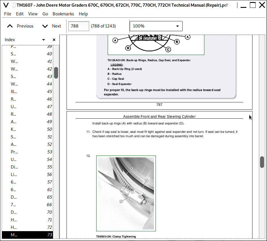
Assemble Front and Rear Steering Cylinder
Assemble Front Steering Cylinder (Without HFWD)
Assemble Steering Valve
Assemble Wheel Lean Cylinder
Disassemble and Inspect Front and Rear Steering Cylinder
Disassemble Front Steering Cylinder (Without HFWD)
Disassemble Steering Valve
Disassemble Wheel Lean Cylinder
Essential Tools
Front Steering Cylinder-Exploded View
Front Steering Cylinder (Without HFWD)-Cross Section
Other Material
Rear Steering Cylinder-Exploded View
Remove and Install Counterbalance Valve
Remove and Install Steering Wheel, Column, and Valve
Service Equipment and Tools
Specifications
Wheel Lean Cylinder-Exploded View
10 - Service Brakes
11 - Active Elements
Brake Backing Plate-Exploded View
Brake Components-Cross Section
Brake Piston Packings-High Pressure Leakdown Test
Brake Piston Packings-Vacuum Leakdown Test
Disassemble and Assemble Service Brake Elements
Essential Tools
Other Material
Specifications
60 - Hydraulic System
Bleeding Service Brake
Disassemble and Assemble Brake Valve
Remove and Install Brake Accumulator
Remove and Install Brake Valve
11 - Park Brake
11 - Active Elements
Apply High Flex Form-in-Place Gasket to Brake Housing
Assemble Brake Piston
Disassemble and Assemble Park Brake
Install Brake Assembly Using High Flex Form-in-Place Gasket
Install Brake Cover
Install Brake Housing With Gasket
Install Brake Hub
Install Clutch Disk and Separator Plates
Other Material
Park Brake Group
Remove Brake Housing
Remove Brake Hub
Remove Brake Piston
Remove Clutch Disks and Separator Plates
Specifications
16 - Electrical System
71 - Batteries, Support and Cables
Adding 12-Volt Accessories
Charge Battery
Check Battery Electrolyte Level and Terminals
Handle Batteries Safely
Other Material
Procedure for Testing Batteries
Remove and Install Batteries
Replacing Batteries
Specifications
Using Booster Batteries-24-Volt System
72 - Alternator, Regulator and Charging System Wiring
John Deere Engine Accessories-Bosch Alternator Repair-Use CTM77
Remove and Install Alternator
Specifications
73 - Lighting System
Remove and Install Halogen Lights
Replace Front Signal Lights
Replace Headlights and Work Lights
Replace Rear Stop, Tail, Signal and Warning Lights
Replace Rear Work Lights
Specifications
74 - Wiring Harness and Switches
Adjust Rear Steering Sensor
Essential Tools
Install CINCH™ Contact
Install DEUTSCH™ Contact
Install WEATHER PACK™ Contact
Remove and Install Engine Controller-CH Models Only
Remove and Install HFWD Controller
Remove and Install HFWD Front Sensor
Remove and Install Rear Steering Sensor
Remove and Install Transmission Controller
Remove Connector Body from Blade Terminals
Replace CINCH™ Connectors
Replace Circular AMP™ Connectors
Replace CPC™ Blade Type Connectors
Replace CPC™ , Large MATE-N-LOC™ and METRIMATE™ Pin Type Connectors
Replace DEUTSCH™ Connectors
Replace DEUTSCH™ Rectangular or Triangular Connectors
Replace METRI-PACK™ Connectors
Replace Small MATE-N-LOC™ Pin Connector
Replace Small MATE-N-LOC™ Socket Connector
Replace SURE-SEAL™ Connectors
Replace SURE-SEAL™ Connector with WEATHER PACK™ Connector
Replace WEATHER PACK™ Connector
Saddle Locking Pin Switch Adjustment
Service Parts Kits
Specifications
75 - System Controls
Remove and Install Air Heat Controller (If Equipped)
Remove and Install Output Shaft Speed Pickup
77 - Motors and Actuators
John Deere Engine Accessories-Starter Repair-Use CTM77
Remove and Install Starter Motor
Specifications
17 - Frame, Chassis or Supporting Structure
40 - Frame Installation
Remove and Install Fan Support
Remove and Install Front Engine Cover Support
Remove and Install Tank and Reservoir Support
Separate Engine and Equipment Frame
Specifications
Welding on Machine
Welding Repair of Major Structure
18 - Operator's Station
00 - Removal and Installation
Remove and Install Cab
Service Equipment and Tools
Specifications
10 - Operation Enclosure
Front Windshield Wiper-Exploded View
Other Material
Remove and Install Cab Doors
Remove and Install Door Latch
Remove and Install Inside Assist Handle-Left Door
Remove and Install Rear Headliner
Remove and Install Rear Wiper
Remove and Install Windowpanes
Remove and Install Windshield Washer
Remove, Install and Adjust Front Windshield Wiper
Specifications
21 - Seat and Seat Belt
Disassemble and Assemble Manual Suspension Seat
Disassemble and Assemble Seat Belt
Disassemble and Assemble Seat
Disassemble and Assemble Tether Strap
30 - Heating and Air Conditioning
Belt Tensioner Spring Check
Charge R134A System
Check Clutch Hub Clearance-R134A
Disassemble and Assemble Blower Motor
Disassemble and Assemble Compressor Clutch-R134A
Disassemble, Inspect and Assemble Compressor-R134A
Essential Tools
Evacuate R134A System
Flush Air Conditioner System
High Pressure Switch Test
Inspect Compressor Manifold-R134A
Leak Testing
Low Pressure Switch Test
Other Material
Proper Refrigerant Handling
Purge Air Conditioner System
R134A Component Oil Charge
R134A Compressor Oil Charge Check
R134A Compressor Oil Information
R134A Compressor Oil Removal
R134A Refrigerant Cautions
R134A Refrigerant Recovery
R134A Refrigerant Recovery _ Recycling and Charging Station Installation Procedures
Refrigerant Hoses and Tubing Inspection
Remove and Install 20,000 BTU Heater Hoses and Controls (SN -567031)
Remove and Install 20,000 BTU Heater Hoses and Controls (SN 567032- )
Remove and Install 20,000 BTU Heater
Remove and Install 40,000 BTU Heater Hoses and Controls
Remove and Install Cab Roof Heater Hoses
Remove and Install Cab Roof Heater
Remove and Install Compressor
Remove and Install Compressor Relief Valve-R134A
Remove and Install Condenser
Remove and Install Defog Ducts
Remove and Install Evaporator and Expansion Valve
Remove and Install High Pressure Switch
Remove and Install Low Pressure Switch
Remove and Install Receiver _ Dryer
Service Equipment and Tools
Specifications
Thermostat Switch Bench Test
99 - Dealer Fabricated Tools
DFRW20 Compressor Holding Fixture
19 - Sheet Metal and Styling
Anti Seize Lubricant
Remove and Install Grille Housing
Specifications
21 - Main Hydraulic System
60 - Hydraulic System
Disassemble and Assemble Main Hydraulic Oil Filter
Disassemble and Assemble Main Hydraulic Pump Control Valve
Disassemble and Assemble Main Hydraulic Pump
Disassemble and Assemble Soft Start Solenoid Valve (If Equipped)
Remove and Install Hydraulic Fluid Reservoir
Remove and Install Main Hydraulic Pump Control Valve
Remove and Install Main Hydraulic Pump
Remove and Install System Relief Valve
Service Equipment and Tools
Specifications
34 - Grading Device
15 - Controls Linakage
Change Two Hand Blade Lift Pattern to One Hand Blade Lift Pattern
Remove and Install Console Tilt Linkage
Remove and Install Steering Support and Console
Remove and Install Steering Tilt Assembly
Service Equipment and Tools
Specifications
40 - Frames
Adjusting Circle Clearance
Disassemble and Assemble Locking Pin
Install and Adjust Blade Side Shift Wear Inserts
Measure and Adjust Blade Side Shift Clearance
Other Material
Remove and Install Draft, Circle, and Blade Tilt Frame_{3715}
Remove and Install Draft, Circle, and Blade Tilt Frame
Remove and Install Lift Arms, Saddle Frame and Locking Pin Bracket
Specifications
50 - Circle Gearbox
Disassemble and Assemble Circle Drive Gearbox (With Slip Clutch)
Disassemble and Assemble Circle Gearbox
Other Material
Service Equipment and Tools
Specifications
60 - Hydraulic System
Assemble Blade Lift, Tilt, Sideshift, or Circle Sideshift Cylinder
Disassemble and Assemble Blade Lift or Scarifier Valve Section
Disassemble and Assemble Circle Rotate Valve Section
Disassemble and Assemble Crossover Relief Valve
Disassemble and Assemble Grader Control Valve
Disassemble and Assemble Priority Control Valve
Disassemble and Assemble Rotary Manifold
Disassemble and Assemble Rotate Motor
Disassemble and Assemble Saddle Locking Pin Solenoid Valve
Disassemble and Assemble Wheel Lean, Rear Steer, Circle Side Shift, Blade Tilt, or Blade Side Shift Valve Section
Disassemble and Inspect Return Check Poppets
Disassemble Blade Lift, Tilt, Sideshift, or Circle Sideshift Cylinder
Other Material
Remove and Install Blade Lift, Blade Tilt and Circle Side Shift Cylinders
Remove and Install Counterbalance Valve
Remove and Install Grader Control Valve
Remove and Install Rotary Manifold
Remove and Install Saddle Locking Pin Solenoid Valve
Service Equipment and Tools
Specifications
42 - Ground Conditioning Tools
40 - Frames
Remove and Install Ripper
Remove and Install Scarifier
60 - Hydraulic System
Assemble Ripper and Scarifier Cylinders
Disassemble Ripper and Scarifier Cylinders
Other Material
Service Equipment and Tools
Specifications
John Deere Motor Graders 670C, 670CH, 672CH, 770C, 770CH, 772CH Service Repair Manual (TM1607)
![]()