
John Deere Motor Graders 670C, 670CH, 672CH, 770C, 770CH, 772CH Series II Service Repair Manual (TM1915)
Complete service repair manual for John Deere Motor Graders 670C, 670CH, 672CH, 770C, 770CH, 772CH Series II, with all the workshop information to maintain, repair, and rebuild like professional mechanics.
John Deere Motor Graders 670C, 670CH, 672CH, 770C, 770CH, 772CH Series II workshop service & repair manual includes:
* Numbered table of contents easy to use so that you can find the information you need fast.
* Detailed sub-steps expand on repair procedure information
* Numbered instructions guide you through every repair procedure step by step.
* Notes, cautions and warnings throughout each chapter pinpoint critical information.
* Bold figure number help you quickly match illustrations with instructions.
* Detailed illustrations, drawings and photos guide you through every procedure.
* Enlarged inset helps you identify and examine parts in detail.
TM1915 - John Deere Motor Graders 670C, 670CH, 672CH, 770C, 770CH, 772CH Series II Technical Manual - Repair.PDF
TM1915 - John Deere Motor Graders 670C, 670CH, 672CH, 770C, 770CH, 772CH Series II Technical Manual - Repair.epub
Total Pages: 804 pages
File Format: PDF/EPUB/MOBI/AZW (PC/Mac/Android/Kindle/iPhone/iPad; bookmarked, ToC, Searchable, Printable)
Language: English
MAIN SECTIONS
Foreword
Technical Information Feedback Form
General Information
Safety
Wheels
Powered Wheels and Fastenings
Axles and Suspension Systems
Input Drive Shafts and U-Joints
Non-Powered Wheel Axles
Axle Shafts, Bearings, and Reduction Gears
Hydraulic System
Dealer Fabricated Tools
Transmission
Removal and Installation
Gears, Shafts, Bearings and Power Shaft Clutch
Hydraulic System
Engine
Removal and Installation
Dealer Fabricated Tools
Engine Auxiliary System
Cold Weather Starting Aids
Cooling System
External Fuel Supply Systems
Torsional Isolator
Elements
Steering System
Power Steering
Hydraulic System
Service Brakes
Active Elements
Hydraulic System
Park Brake
Active Elements
Frame, Chassis or Supporting Structure
Frame Installation
Operator’s Station
Removal and Installation
Operator Enclosure
Seat and Seat Belt
Heating and Air Conditioning
Dealer Fabricated Tools
Sheet Metal and Styling
Covers and Guards
Hood or Engine Enclosure
Grille and Grille Housing
Main Hydraulic System
Hydraulic System
Grading Device
Controls Linkage
Frames
Circle Gearbox
Hydraulic System
Ground Conditioning Tool
Frames
Hydraulic System
tm1915 - C Series II Motor Graders
Table of Contents
Foreword
Technical Information Feedback Form
Section 00: General Information
Group 001: Safety
Recognize Safety Information
Follow Safety Instructions
Operate Only If Qualified
Wear Protective Equipment
Avoid Unauthorized Machine Modifications
Inspect Machine
Stay Clear of Moving Parts
Avoid High-Pressure Fluids
Beware of Exhaust Fumes
Prevent Fires
Prevent Battery Explosions
Handle Chemical Products Safely
Dispose of Waste Properly
Prepare for Emergencies
Use Steps and Handholds Correctly
Start Only From Operator's Seat
Use and Maintain Seat Belt
Prevent Unintended Machine Movement
Avoid Work Site Hazards
Keep Riders Off Machine
Avoid Backover Accidents
Avoid Machine Tip Over
Operating or Traveling On Public Roads
Inspect and Maintain ROPS
Add and Operate Attachments Safely
Park And Prepare For Service Safely
Service Cooling System Safely
Remove Paint Before Welding or Heating
Make Welding Repairs Safely
Drive Metal Pins Safely
Section 01: Wheels
Group 0110: Powered Wheels and Fastenings
Remove and Install Tire
Section 02: Axles and Suspension Systems
Group 0225: Input Drive Shafts and U-Joints
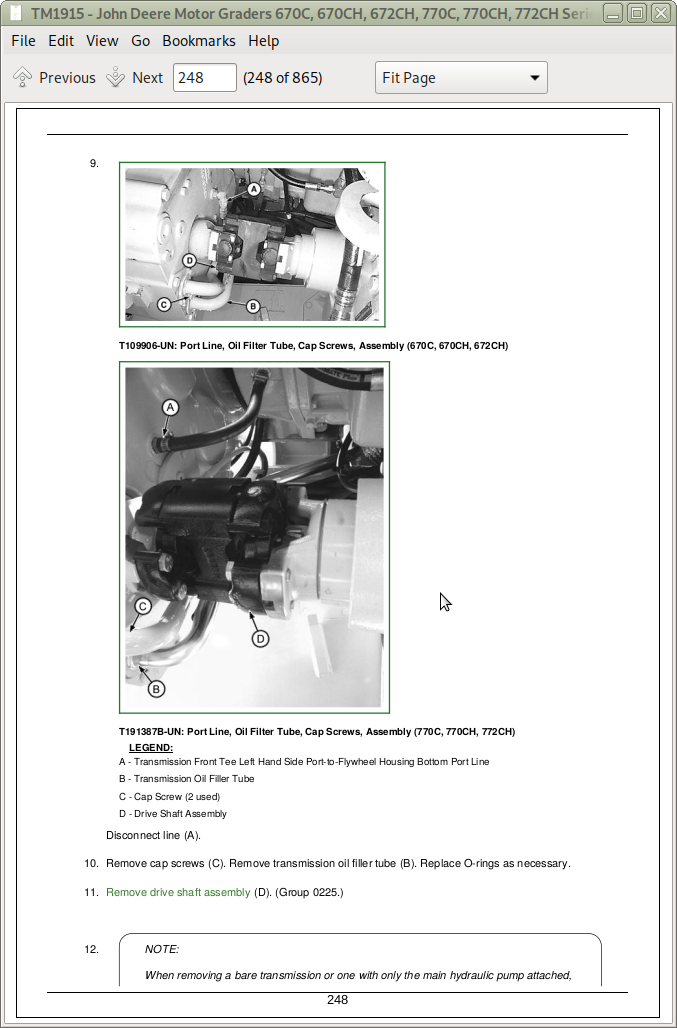
Remove and Install Transmission to Rear Axle Drive Shaft
Disassemble and Assemble Transmission to Rear Axle Drive Shaft
Group 0230: Non-Powered Wheel Axles
Other Material
Specifications
Remove and Install Front Wheel Hub and Spindle
Remove and Install Front Wheel Hub
Remove and Install Front Axle—(SN —592109)
Remove and Install Front Axle—(SN 592110— )
Group 0250: Axle Shafts, Bearings, and Reduction Gears
Service Equipment and Tools
Other Material
TEAMMATE TEAMMATE is a trademark of Deere & Company II 1400 Series Inboard Planetary Axle—Use CTM43
Remove and Disassemble Rear Axle
Assemble and Install Rear Axle
Remove and Install Tandem and Wheel Axle Assembly
Remove and Install Tandem Rear Wheel Axle Assembly
Remove and Install Tandem Front Wheel Axle Assembly
Disassemble and Assemble Tandem Pivot
Remove and Install Final Drive Axle (S.N. —562099)
Remove and Install Final Drive Axle (S.N. 562100— )
Disassemble Final Drive Axle Housing
Assemble Final Drive Axle Housing
Remove Brake Backing Plate, Brake Disks and Separator Plate
Brake Disk Inspection
Install Brake Backing Plate, Disks and Separator Plates
Remove and Disassemble Planet Pinion Carrier
Assemble and Install Planet Pinion Carrier
Remove and Disassemble Tandem Drive Shaft
Assemble and Install Tandem Drive Shaft
Disassemble Final Drive Axle Housing
Assemble Final Drive Axle Housing
Remove and Install Drive Chain
Disassemble and Assemble Tandem Wheel Axle Assemblies
Inspect Metal Face Seals
HFWD Lean Yoke Assembly Repair
HFWD Drive Hub Assembly Disassemble and Assemble
Planetary Drive Disassemble and Assemble
Planetary Brake Disassemble and Assemble
HFWD Bearings Remove and Install
HFWD O-Ring Metal Face Seal Remove and Install
Remove and Install Front Axle With HFWD
Group 0260: Hydraulic System
Remove and Install HFWD Pumps
Disassemble and Assemble HFWD Pump
Remove and Install Differential Lock Pump
Remove and Install Differential Lock and Park Brake Valve
Disassemble and Assemble Differential Lock and Park Brake Valve
HFWD Motor Repair
Group 0299: Dealer Fabricated Tools
DFT1151—Outboard Bearing Driver
DFT1152—Inboard Bearing Driver
DFT1153—Oil Seal Driver
DF1017—Axle Lift Eye
DF1057—Axle Adjusting Tool
DFRW103—Yoke Holding Tool Tool may be purchased. Order JDG924.
DFT1225—Rolling Torque Measurement Tool
Section 03: Transmission
Group 0300: Removal and Installation
Service Equipment and Tools
Other Material
Remove and Install Transmission
Install Transmission Harness
Group 0350: Gears, Shafts, Bearings and Power Shaft Clutch
Essential Tools
Other Material
Use Proper Lifting Equipment
Mounting Transmission on Repair Stand
Remove Yoke Assembly
Install Slip Yoke Assembly
Remove Output Oil Seal
Install Output Oil Seal
Remove and Install Oil Drain Plug
Remove Drive Hub
Install Drive Hub
Remove and Install Charge Pump Group
Remove Accumulator Group
O-Ring Adapter
90° Male Elbow
Transmission Accumulator
Install Accumulator Group
Remove Valve Assembly
Remove Gaskets and Plate from Rear Housing
Disassemble Valve Assembly
Remove Relief Valve
Remove Main Regulator Assembly
Remove Temperature Sensor
Remove Plugs
Valve Assembly
Assemble Valve Assembly
Install Temperature Sensor
Install Main Regulator Assembly
Install Relief Valve
Install Proportional Solenoid Assembly
Install Gasket to Rear Housing
Install Plate and Gasket
Install Valve Assembly
Control Valve Cap Screws
Cap Screw Tightening Sequence and Torque Specifications
Park Brake Group
Remove and Disassemble Park Brake
Remove Brake Piston
Remove Brake Hub
Remove Clutch Disks and Separator Plates
Remove Brake Housing
Apply High Flex Form-In-Place Gasket to Brake Housing
Install Brake Assembly Using High Flex Form-in-Place Gasket
Install Brake Housing With Gasket
Install Brake Hub
Install Clutch Disk and Separator Plates
Assemble Brake Piston
Install Brake Cover
Remove Idler Shafts
Remove Hex Cap Screws
Remove Rear Housing
Rear Housing—Front View
Remove Bore Sleeves
Install Bore Sleeves
Remove Bearing Cup
Install Bearing Cup
Remove Lube Relief Valve
Rear Housing—Rear View
Install Lube Relief Valve
Install Pluget
Remove First Stage Oil Seal
Install First Stage Oil Seal
Install Seal Rings
Install JDG1102 Lifting Tool
Install Idler Shafts
Remove and Install Oil Trough Assembly
Remove All Stage Assemblies
Remove Clutch Stack Nest Lift Plate
Gear Stage Assembly
First Stage Assembly
Disassemble First Stage Shaft Assembly
Assemble First Stage Shaft Assembly
Second Stage Clutch Assembly (Directional Clutch)
Third Stage Clutch Assembly (Directional Clutch)
Disassemble Second and Third Stage Clutch Assembly
Remove Clutch Return Spring
Remove Clutch Piston
Assemble Second and Third Stage Clutch Assembly
Fourth Stage Clutch Assembly (Speed Clutch)
Fifth Stage Clutch Assembly (Speed Clutch)
Disassemble Fourth and Fifth Stage Clutch Assembly (Speed Clutch)
Assemble Fourth and Fifth (Speed Clutch)
Sixth Stage Assembly
Disassemble Sixth Stage Assembly
Assemble Sixth Stage Assembly
Remove Output Group
Disassemble Output Group
Output Group
Assemble Output Group
Install Output Group Assembly
Arrange Stage Assemblies Into Clutch Stack Nest Fixture
Disassemble Front Housing Assembly
Disassemble Pump Output Gear Assembly
Assemble Pump Output Gear Assembly
Remove Pump Idler Gears and Disassemble
Assemble Pump Idler Gear Assemblies
Remove and Install Bearing Cups
Install Pump Drive Gear Assemblies
Install Output Group
Use Proper Lifting Equipment
Install Clutch Stack Lift Tool
Install Stage Assembly
Install Oil Trough
Install Seal Rings
Install Rear Housing
Install Idler Shafts
Install Control Valve Group
Install Accumulator Group
Remove Sixth Stage Bearing Retainer
Bearing Adjustment of Sixth Stage Assembly
Install Brake Assembly
Install Charge Pump to Front Housing
Install Drive Hub
Install Slip Yoke Assembly
Group 0360: Hydraulic System
Specifications
Remove and Install Transmission Charge Pump
Disassemble and Assemble Transmission Filter
Section 04: Engine
Group 0400: Removal and Installation
Engine Remove and Install—6068
Remove and Install Engine—6081
Remove and Install Engine Oil Pan—6068 Engine
Remove and Install Engine Oil Pan—6081 Engine
Bleed the Fuel System—670C
Bleed the Fuel System—770C
Relieve Fuel System Pressure
Replace Rectangular Fuel Filter Element
Replace Fuel Filter Check Valve
Belt Routing
Group 0499: Dealer Fabricated Tools
DFT1150 Transmission Support Bracket
Section 05: Engine Auxiliary System
Group 0505: Cold Weather Starting Aids
Engine Coolant Heater Repair
Group 0510: Cooling System
Fan Pulley Repair
Fan Belt Adjuster Repair
Fan Shroud Repair
Fan Drive Assembly
Fan Drive Hub Repair
Radiator Repair
Oil Cooler Repair
Aftercooler Repair
Group 0560: External Fuel Supply Systems
Fuel Tank Remove and Install (S.N. —589368)
Fuel Tank Remove and Install (S.N. 589369— )
Section 07: Torsional Isolator
Group 0752: Elements
Torsional Isolator Repair
Section 09: Steering System
Group 0920: Power Steering
Check and Adjust Toe-In (HFWD or Non-HFWD)
Group 0960: Hydraulic System
Essential Tools
Service Equipment and Tools
Other Material
Disassemble Steering Valve
Assemble Steering Valve
Remove and Install Steering Wheel, Column, and Valve
Remove and Install Counterbalance Valve
Disassemble Front Steering Cylinder (Without HFWD)
Assemble Front Steering Cylinder (Without HFWD)
Disassemble and Inspect Front Steering Cylinder
Assemble Front Steering Cylinder
Disassemble and Assemble Rear Steering Cylinder
Disassemble Wheel Lean Cylinder
Assemble Wheel Lean Cylinder
Section 10: Service Brakes
Group 1011: Active Elements
Essential Tools
Other Material
Specifications
Brake Components—Cross Section
Brake Backing Plate—Exploded View
Disassemble and Assemble Service Brake Elements
Brake Piston Packings—Vacuum Leak Down Test
Brake Piston Packings—High Pressure Leak Down Test
Group 1060: Hydraulic System
Remove and Install Brake Valve
Disassemble and Assemble Brake Valve
Bleeding Service Brake
Remove and Install Brake Accumulator
Section 11: Park Brake
Group 1111: Active Elements
Other Material
Disassemble and Assemble Park Brake
Remove Brake Piston
Remove Brake Hub
Remove Clutch Disks and Separator Plates
Remove Brake Housing
Park Brake Group
Apply High Flex Form-in-Place Gasket to Brake Housing
Install Brake Assembly Using High Flex Form-in-Place Gasket
Install Brake Housing With Gasket
Install Brake Hub
Install Clutch Disk and Separator Plates
Assemble Brake Piston
Install Brake Cover
Section 17: Frame, Chassis or Supporting Structure
Group 1740: Frame Installation
Welding on Machine
Welding Repair of Major Structure
Remove and Install Front Engine Cover Support (S.N. —589368)
Remove and Install Tank and Reservoir Support (With Reservoirs)
Fan Support
Section 18: Operator’s Station
Group 1800: Removal and Installation
Service Equipment and Tools
Remove and Install Cab
Group 1810: Operator Enclosure
Other Material
Specifications
Remove and Install Windowpanes
Remove and Install Cab Doors
Remove and Install Door Latch
Remove and Install Inside Assist Handle—Left Door
Remove and Install Windshield Washer
Remove, Install, and Adjust Front Windshield Wiper
Remove and Install Rear Wiper
Remove and Install Rear Headliner
Group 1821: Seat and Seat Belt
Disassemble and Assemble Seat, Armrest, and Seat Belt
Disassemble and Assemble Seat with Mechanical Suspension and Tether Strap
Disassemble and Assemble Seat Slide
Disassemble and Assemble Lumbar Support and Control
Disassemble and Assemble Seat Riser
Disassemble and Assemble Air or Mechanical Suspension Seat with Headrest
Group 1830: Heating and Air Conditioning
Refrigerant Cautions and Proper Handling
Flush and Purge Air Conditioner System
R134a Refrigerant Oil Information
R134a Refrigerant Recovery/Recycling and Charging Station Installation Procedure
Recover R134a Refrigerant
Evacuate R134a System
Charge R134a System
Remove and Install Compressor
Remove and Install High Pressure Switch
Disassemble and Assemble Compressor Clutch
Inspect Compressor Manifold
Remove and Install Condenser
Evaporator and Expansion Valve
Remove and Install Receiver/Dryer
Remove and Install Accumulator
Remove and Install Compressor Relief Valve
Remove and Install Low Pressure Switch
Remove and Install 20,000 BTU Heater
Remove and Install 20,000 BTU Heater Hoses and Controls
Remove and Install 40,000 BTU Heater Hoses and Controls
Remove and Install Cab Roof Heater
Group 1899: Dealer Fabricated Tools
DFRW20 Compressor Holding Fixture
Section 19: Sheet Metal and Styling
Group 1900: Covers and Guards
Anti Seize Lubricant
Group 1910: Hood or Engine Enclosure
Engine Enclosure Remove and Install (S.N. 589369— )
Group 1921: Grille and Grille Housing
Grille Housing Repair (S.N. —589368)
Grille Housing Repair (S.N. 589369— )
Section 21: Main Hydraulic System
Group 2160: Hydraulic System
Service Equipment and Tools
Remove and Install Main Hydraulic Pump
Disassemble and Assemble Main Hydraulic Pump
Remove and Install System Relief Valve
Remove and Install Hydraulic Fluid Reservoir (S.N. —589368)
Hydraulic Fluid Reservoir Remove and Install (S.N. 589369— )
Remove and Install Attenuator
Section 34: Grading Device
Group 3415: Controls Linkage
Service Equipment and Tools
Remove and Install Steering Support and Console
Change Two Hand Blade Lift Pattern to One Hand Blade Lift Pattern
Remove and Install Steering Tilt Assembly
Remove and Install Console Tilt Linkage
Group 3440: Frames
Other Material
Remove and Install Lift Arms, Saddle Frame and Locking Pin Bracket
Disassemble and Assemble Locking Pin
Remove and Install Draft, Circle, and Blade Tilt Frame
Remove and Install Draft, Circle, and Blade Tilt Frame
Circle Adjustment
Install and Adjust Blade Side Shift Wear Inserts
Measure and Adjust Blade Side Shift Clearance
Group 3450: Circle Gearbox
Service Equipment and Tools
Other Material
Disassemble and Assemble Circle Gearbox
Disassemble and Assemble Circle Drive Gearbox (With Slip Clutch)
Group 3460: Hydraulic System
Service Equipment and Tools
Other Material
Remove and Install Grader Control Valve
Disassemble and Assemble Grader Control Valve
Disassemble and Assemble Blade Lift or Scarifier Valve Section
Disassemble and Assemble Wheel Lean, Rear Steer, Circle Side Shift, Blade Tilt, or Blade Side Shift Valve Section
Disassemble and Assemble Circle Rotate Valve Section
Disassemble and Inspect Return Check Poppets
Disassemble and Assemble Priority Control Valve
Disassemble and Assemble Rotate Motor
Remove and Install Rotary Manifold
Disassemble and Assemble Rotary Manifold
Remove and Install Saddle Locking Pin Solenoid Valve
Disassemble and Assemble Saddle Locking Pin Solenoid Valve
Disassemble and Assemble Crossover Relief Valve
Remove and Install Counterbalance Valve
Remove and Install Blade Lift, Blade Tilt and Circle Side Shift Cylinders
Disassemble Blade Lift, or Circle Side Shift Cylinder
Assemble Blade Lift or Circle Side Shift Cylinder
Disassemble and Assemble Blade Tilt and Blade Side Shift Cylinders
Section 42: Ground Conditioning Tool
Group 4240: Frames
Remove and Install Scarifier
Remove and Install Ripper
Group 4260: Hydraulic System
Service Equipment and Tools
Other Material
Specifications
Disassemble Scarifier Cylinders
Assemble Scarifier Cylinders
Disassemble and Assemble Ripper Cylinder
John Deere Motor Graders 670C, 670CH, 672CH, 770C, 770CH, 772CH Series II Service Repair Manual (TM1915)
![]()