
John Deere Motor Graders 670D, 672D, 770D, 772D, 870D, 872D Operation and Test Service Manual (TM2246)
Complete Operation and Test service manual with Electrical Wiring Diagrams for John Deere Motor Graders 670D, 672D, 770D, 772D, 870D, 872D, with all the technical information to maintain, test, and service like professional mechanics.
John Deere Motor Graders 670D, 672D, 770D, 772D, 870D, 872D workshop Diagnostics and Test manual includes:
* Numbered table of contents easy to use so that you can find the information you need fast.
* Detailed sub-steps expand on repair procedure information
* Numbered instructions guide you through every repair procedure step by step.
* Troubleshooting and electrical service procedures are combined with detailed wiring diagrams for ease of use.
* Notes, cautions and warnings throughout each chapter pinpoint critical information.
* Bold figure number help you quickly match illustrations with instructions.
* Detailed illustrations, drawings and photos guide you through every procedure.
* Enlarged inset helps you identify and examine parts in detail.
TM2246 - John Deere Motor Graders 670D, 672D, 770D, 772D, 870D, 872D Technical Manual - Operation and Test.PDF
tm2953 - John Deere Motoniveladoras 670D, 672D, 770D, 772D, 870D y 872D.pdf
tm10016 - John Deere Niveleuses 670D, 672D, 770D, 772D, 870D et 872D.pdf
Category: Operation and Test
Language: Spanish French English
Published on 2019/02/11
Total Pages: 814 pages
File Format: PDF/EPUB/MOBI/AZW (PC/Mac/Android/Kindle/iPhone/iPad; bookmarked, ToC, Searchable, Printable)
MAIN SECTIONS
Foreword
Technical Information Feedback Form
General Information
Safety
Operational Checkout Procedure
Operational Checkout Procedure
Engine
Theory Of Operation
Diagnostic Information
Tests
Electrical System
System Information
System Diagrams
Sub-System Diagnostics
References
Hydrostatic Front Wheel Drive (HFWD)
Theory Of Operation
Diagnostic Information
Adjustments
Tests
Power Train
Theory Of Operation
Diagnostic Information
Tests
Hydraulic System
Theory Of Operation
Diagnostic Information
Tests
Heating And Air Conditioning
Theory Of Operation
Diagnostic Information
Adjustments
Tests
TABLE OF CONTENTS - Expanded View
9000 - GENERAL INFORMATION
01 - Safety
Add and Operate Attachments Safely
Avoid Backover Accidents
Avoid High-Pressure Fluids
Avoid High-Pressure Oils
Avoid Machine Tip-Over
Avoid Unauthorized Machine Modifications
Avoid Worksite Hazards
Beware of Exhaust Fumes
Dispose of Waste Properly
Drive Metal Pins Safely
Follow Safety Instructions
Handle Chemical Products Safely
Inspect and Maintain ROPS
Inspect Machine
Keep Riders Off Machine
Make Welding Repairs Safely
Operate Only If Qualified
Operating Or Traveling On Public Roads
Park And Prepare For Service Safely
Prepare for Emergencies
Prevent Battery Explosions
Prevent Fires
Prevent Unintended Detonation of Explosive Devices
Prevent Unintended Machine Movement
Recognize Safety Information
Remove Paint Before Welding or Heating
Service Cooling System Safely
Start Only From Operator's Seat
Stay Clear of Moving Parts
Use and Maintain Seat Belt
Use Steps and Handholds Correctly
Wear Protective Equipment
9005 - OPERATIONAL CHECKOUT PROCEDURE
10 - Operational Checkout Procedure
Operational Checkout_{3211}
Operational Checkout
9010 - ENGINE
05 - Theory of Operation
Cold Weather Starting Aid Theory Of Operation
Engine Speed Theory Of Operation
Pilot Injection Theory Of Operation
POWERTECH ® 4.5 L & 6.8 L (4045 & 6068) John Deere Engines
POWERTECH ® 8.1 L (6081) John Deere Engines
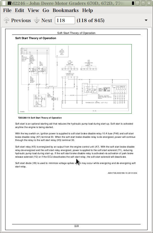
Soft Start Theory of Operation
15 - Diagnostic Information
Diagnose Observable Machine Symptoms—Level 11 Electronic Fuel System—670D and 672D Grader
Diagnose Observable Machine Symptoms—Level 9 Electronic Fuel System—770D, 772D, 870D, and 872D Grader
Engine Cooling System Component Location—6.8 L
Engine Cooling System Component Location—8.1 L
Engine Fuel System Component Location—6.8 L
Engine Fuel System Component Location—8.1 L
Engine Sampling Port Location
POWERTECH ® 4.5 L & 6.8 L (4045 & 6068) John Deere Engines
POWERTECH ® 8.1 L (6081) John Deere Engines
25 - Tests
Fan Belt Tensioner Spring Check
Intake Manifold Pressure Test—Turbocharger Boost—6.8 L
Intake Manifold Pressure Test—Turbocharger Boost—8.1 L
Turbocharger Wastegate Actuator Test—8.1 L
9015 - ELECTRICAL SYSTEM
05 - System Information
Electrical Diagram Information
Electrical Diagram Information (S.N. —165691)
10 - System Diagrams
Air Conditioning Harness (W14) Component Location
Air Conditioning Harness (W14) Wiring Diagram
Blade Impact Harness (W19) Component Location
Blade Impact Harness (W19) Wiring Diagram
Cab Interior Harness (W2) Component Location—HFWD (6WD) (S.N. —611295)
Cab Interior Harness (W2) Component Location—HFWD (6WD) (S.N. 611296— )
Cab Interior Harness (W2) Wiring Diagram—HFWD (6WD) (S.N. —611295)
Cab Interior Harness (W2) Wiring Diagram—HFWD (6WD) (S.N. 611296— )
Cab Interior Harness (W3) Component Location—Non HFWD (6WD)
Cab Interior Harness (W3) Wiring Diagram—Non HFWD (6WD) (S.N. —611295)
Cab Interior Harness (W3) Wiring Diagram—Non HFWD (6WD) (S.N. 611296— )
Cab Roof Harness (W14) Component Location
Cab Roof Harness (W14) Wiring Diagram
Cab Roof Harness (W9) Component Location
Cab Roof Harness (W9) Wiring Diagram
Canopy Roof Harness (W8) Component Location
Canopy Roof Harness (W8) Wiring Diagram
Console Harness (W16) Component Location
Console Harness (W16) Wiring Diagram
Drive _ Turn Light Harness (W22) Component Location—Right Front
Drive _ Turn Light Harness (W22) Wiring Diagram—Right Front
Drive _ Turn Light Harness (W23) Component Location—Left Front
Drive _ Turn Light Harness (W23) Wiring Diagram—Left Front
Engine Harness (W10) Component Location
Engine Harness (W10) Wiring Diagram
Engine Harness (W6) Component Location—6.8 L
Engine Harness (W6) Wiring Diagram—6.8 L
Engine Harness (W7) Component Location—8.1 L
Engine Harness (W7) Wiring Diagram—8.1 L
Front HFWD (6WD) Harness (W10) Component Location (S.N. —611295)
Front HFWD (6WD) Harness (W10) Component Location (S.N. 611296— )
Front HFWD (6WD) Harness (W10) Wiring Diagram (S.N. —611295)
Front HFWD (6WD) Harness (W10) Wiring Diagram (S.N. 611296— )
Front Platform Harness (W4) Component Location
Front Platform Harness (W4) Wiring Diagram
Fuse and Relay Specifications
Fuse and Relay Specifications
Heater and Air Conditioner Harness (W12) Component Location
Heater and Air Conditioner Harness (W12) Wiring Diagram
IGC Machine Harness (W21) and IGC Cab Harness (W22) Component Location
Integrated Grade Control (IGC) Cab Harness (W22) Wiring Diagram
Integrated Grade Control (IGC) Machine Harness (W21) Wiring Diagram
Integrated Grader Control Harness (W25) Component Location—Trimble
Integrated Grader Control Harness (W25) Wiring Diagram—Trimble
Integrated Grader Control Harness (W26) Component Location—Topcon
Integrated Grader Control Harness (W26) Wiring Diagram—Topcon
JDLink™ System Functional Schematic—MIG _ GTT
JDLink™ System Functional Schematic—MTG _ SAT
JDLink™ System Harnesses Component Location—MIG _ GTT
JDLink™ System Harnesses Component Location—MTG _ SAT
JDLink™ System Wiring Diagrams—MIG _ GTT
JDLink™ System Wiring Diagrams—MTG _ SAT
Left Wheel Speed Sensor Harness (W17) Component Location—HFWD (6WD)
Left Wheel Speed Sensor Harness (W17) Wiring Diagram—HFWD (6WD)
Monitor Harness (W15) Component Location
Monitor Harness (W15) Wiring Diagram
Operator's Station Harness (W7) Component Location
Operator's Station Harness (W7) Wiring Diagram
Radio Harness (W13) Component Location
Radio Harness (W13) Wiring Diagram
Radio Harness (W15) Component Location
Radio Harness (W15) Wiring Diagram
Rear HFWD (6WD) Harness (W11) Component Location
Rear HFWD (6WD) Harness (W11) Wiring Diagram
Rear Platform Harness (W5) Component Location
Rear Platform Harness (W5) Wiring Diagram
Right Wheel Speed Sensor Harness (W18) Component Location—HFWD (6WD)
Right Wheel Speed Sensor Harness (W18) Wiring Diagram—HFWD (6WD)
Steering Angle Sensor Harness (W24) Component Location—HFWD (6WD)
Steering Angle Sensor Harness (W24) Wiring Diagram—HFWD (6WD)
System Functional Schematic and Schematic Legend
System Functional Schematic (S.N. —611295)
System Functional Schematic (S.N. 611296— )
System Functional Schematic, Wiring Diagram, and Component Location Master Legend
Transmission Harness (W11) Component Location
Transmission Harness (W11) Wiring Diagram
Transmission Harness (W8) Component Location
Transmission Harness (W8) Wiring Diagram
Turn _ Tail _ Stop Light Harness (W20) Component Location
Turn _ Tail _ Stop Light Harness (W20) Wiring Diagram
15 - Sub-System Diagnostics
CAN Monitor Unit (CMU) Circuit Theory of Operation
CAN Monitor Unit (CMU) Circuit Theory of Operation
Controller Area Network (CAN) Theory of Operation
Controller Area Network Theory of Operation
Engine Control Unit (ECU) Circuit Theory of Operation
Engine Control Unit (ECU) Circuit Theory of Operation
Flex Load Controller (FLC) Circuit Theory of Operation
Hydrostatic Front Wheel Drive (HFWD) Control Unit Circuit Theory of Operation (S.N. —611295)
Hydrostatic Front Wheel Drive (HFWD) Control Unit Circuit Theory of Operation (S.N. 611296— )
Integrated Grade Control (IGC) Theory of Operation—If Equipped
Starting and Charging Circuit Theory of Operation
Starting and Charging Circuit Theory of Operation
Transmission Control Unit (TCU) Circuit Theory of Operation
Transmission Control Unit (TCU) Circuit Theory of Operation
20 - References
Alternator Test
Alternator Test Procedure
Articulation Sensor Adjustment (Rear Steer)
CAN Circuit Testing
CAN Monitor Unit (CMU) Diagnostic Trouble Codes
CAN Monitor Unit (CMU) Reprogramming
Controller Remove and Install
Diagnostic Trouble Code Quick Reference List
Electrical Component Checks
Electrical Component Specifications
Engine Control Unit (ECU) Diagnostic Trouble Codes
Flex Load Controller (FLC) Diagnostic Trouble Codes
Flex Load Controller (FLC) Outputs
Hydrostatic Front Wheel Drive (6WD) Controller Calibration (S.N. —611295)
Hydrostatic Front Wheel Drive (6WD) Controller Calibration (S.N. 611296— )
Hydrostatic Front Wheel Drive (HFWD) Diagnostic Trouble Codes (S.N. —611295)
Hydrostatic Front Wheel Drive (HFWD) Diagnostic Trouble Codes (S.N. 611296— )
Inching Pedal Module Test
Install CINCH ™ Contact
Install DEUTSCH ™ Contact
Install WEATHER PACK ™ Contact
JDLink™ Connection Procedure—If Equipped
JDLink™ System Identification
Lower Windshield Wiper Proximity Switch Adjustment and Installation
Park _ Not Neutral Gear Position Switch Module (S3) and Forward _ Reverse Switch Module (S5) Remove and Install
Park _ Not Neutral Gear Position Switch Module (S3) and Forward _ Reverse Switch Module (S5) Test
Relay Test
Repair 32 and 48 Way CINCH ™ Connectors
Replace CINCH ™ Connectors
Replace DEUTSCH ™ Connectors
Replace DEUTSCH ™ Rectangular or Triangular Connectors
Replace (Pull Type) Metri-Pack™ Connectors
Replace (Push Type) Metri-Pack™ Connectors
Replace WEATHER PACK ™ Connector
Sealed Switch Module (SSM) Diagnostic Trouble Codes
Transmission Control and Park Brake Lever Test
Transmission Control Unit Calibration
Transmission Control Unit (TCU) Diagnostic Trouble Codes
9016 - HYDRAULIC FRONT WHEEL DRIVE
05 - Theory of Operation
Flushing Valve and Operating Charge Pressure Regulating Valve Operation
HFWD Charge Pump Operation
HFWD Circuit Relief and Make-Up Valve Operation
HFWD Engagement Manifold Operation
HFWD Forward Operation
HFWD Motor Operation
HFWD Precision Mode Operation
HFWD Pump And Displacement Control Operation
HFWD Pump And Motor Flushing Pump Operation
HFWD Wheel Operation
Hydrostatic Front Wheel Drive (HFWD) System Operation
15 - Diagnostic Information
Diagnose Hydrostatic Front Wheel Drive Malfunctions
HFWD System Component Location
HFWD System Schematic
20 - Adjustments
HFWD Pump Control Neutral Adjustment
HFWD Start-Up Procedure
25 - Tests
Avoid High-Pressure Fluids
HFWD Charge Pump Flow Test
HFWD Engagement Solenoid Valve Test
HFWD Motor Flushing Pump Relief Valve Test
HFWD Motor Leakage Test
HFWD Neutral Charge Pressure Balance Test
HFWD Neutral Charge Pressure Regulating Valve Test
HFWD Neutral Charge Pressure Test
HFWD Oil Warm-Up Procedure
HFWD Operating Charge Pressure Regulating Valve Test
HFWD Planetary Brake Leakage Test
HFWD Pump Leakage Test
Hydraulic Oil Cooler Bypass Valve Pressure Test
Pressure Override Valve and HFWD Circuit Relief and Make-Up Valve Test
9020 - POWER TRAIN
05 - Theory of Operation
Differential Lock Operation
Funk Transmission Operation
Park Brake Valve Operation
Rear Axle and Tandem Operation
Transmission Accumulator Operation
15 - Diagnostic Information
Diagnose Differential Lock Malfunctions
Diagnose Park Brake Malfunctions
Diagnose Transmission Malfunctions
Power Train Component Location
Power Train System Schematic
25 - Tests
Differential Lock Valve Pressure Test
Differential Oil Cooler Flow Test
Differential Oil Cooler Relief Valve Pressure Test
Differential Oil Warm-Up Procedure
Park Brake Release Pressure Test
Park Brake Warm-Up Circuit Test
9025 - HYDRAULICS SYSTEM
05 - Theory of Operation
Blade Impact Absorption System Operation
Blade Lift, Ripper, and Scarifier Valve Operation
Brake Accumulator Operation
Circle Drive Gearbox Operation—Without Slip Clutch
Circle Drive Gearbox Operation—With Slip Clutch
Circle Rotate Valve Operation
Circuit Relief Valve Operation
Control Valve Operation—Left
Control Valve Operation—Right
Hydraulic Oil Filter Operation
Hydraulic Pump Operation
Hydraulic System Manifold Operation
Hydraulic System Operation
Load Sense Operation With All Functions in Neutral
Load Sense Operation With Multiple Functions Activated
Load Sense Operation With One Function Activated
Saddle Locking Pin Valve Operation
Service Brake Valve Operation
Steering System Operation
System Relief Valve Operation
Wheel Lean, Articulation, Circle Side Shift, Blade Tilt, and Blade Side Shift Valve Operation
15 - Diagnostic Informtion
Diagnose Hydraulic System Malfunctions
Diagnose Service Brakes Malfunctions
Diagnose Steering System Malfunctions
Hydraulic System Component Location
Hydraulic System Schematic
25 - Tests
Blade Impact Absorption Accumulator Charge Pressure Test
Blade Lift Relief Valve Test
Brake Accumulator Inlet Check Valve Leakage Test
Brake Accumulator Precharge Test
Brake Pressure Switch Test
Brake Valve Leakage Test
Brake Valve Pressure Test
Circuit Relief Valve Test—Midmount Scarifier
Hydraulic Cylinder Drift Test
Hydraulic Cylinder Leakage Test
Hydraulic Oil Cleanup Procedure
Hydraulic Oil Warm-Up Procedure
Hydraulic Pump Flow Test
Hydraulic Pump Leakage Test
Hydraulic Pump Standby Pressure & Load Sense Standby Pressure Test
Hydraulic Test Port Location
JT02156A Digital Pressure And Temperature Analyzer Installation
JT05800 Digital Thermometer Installation
JT07148 Digital Hydraulic Tester
Load Sense Relief Valve & Pump Relief Test
Load Sense Shuttle Valve Isolation Test
Rotary Manifold Leakage Test
Saddle Locking Cylinder Pressure Reducing Valve Test
Steering System Leakage Test
System Relief Valve Pressure Test
Vacuum Pump Installation
9031 - HEATING AND AIR CONDITIONING
05 - Theory of Operation
Air Conditioning System Cycle Of Operation
15 - Diagnostic Informtion
Air Conditioner and Heater Component Location
Diagnose Air Conditioning System Malfunctions
Diagnose Heater System Malfunctions
20 - Adjustments
Defog _ Defrost Cable Adjustment
Heater Control Cable Adjustment
25 - Tests
Air Conditioner and Heater Operational Checks
Air Conditioner Compressor Clutch Test
Air Conditioner Freeze Control Switch Test
Air Conditioner High _ Low Pressure Switch Test
Operating Pressure Diagnostic Chart
R134a Air Conditioning System Test
Refrigerant Cautions and Proper Handling
Refrigerant Leak Test
John Deere Motor Graders 670D, 672D, 770D, 772D, 870D, 872D Operation and Test Service Manual (TM2246)
![]()