
John Deere Scrapers 762B Series II Service Repair Manual (TM1674)
JComplete service repair manual for John Deere Scrapers 762B Series II, with all the workshop information to maintain, repair, and rebuild like professional mechanics.
John Deere Scrapers 762B Series II workshop service & repair manual includes:
* Numbered table of contents easy to use so that you can find the information you need fast.
* Detailed sub-steps expand on repair procedure information
* Numbered instructions guide you through every repair procedure step by step.
* Notes, cautions and warnings throughout each chapter pinpoint critical information.
* Bold figure number help you quickly match illustrations with instructions.
* Detailed illustrations, drawings and photos guide you through every procedure.
* Enlarged inset helps you identify and examine parts in detail.
TM1674 - John Deere 762B Series II Scrapers Technical Manual - Repair.PDF
TM1674 - John Deere 762B Series II Scrapers Technical Manual - Repair.epub
PRODUCT DETAILS:
Total Pages: 912 pages
File Format: PDF/EPUB/MOBI/AZW (PC/Mac/Android/Kindle/iPhone/iPad; bookmarked, ToC, Searchable, Printable)
Language: English
MAIN SECTIONS 762B-II (SN. from 818909)
Foreword
Technical Information Feedback Form
General Information
Safety
General Specifications
Torque Values
Fuels and Lubricants
Wheels
Powered Wheels and Fastenings
Axles and Suspension System
Drive Axle Housing and Support
Controls Linkage
Input Drive Shaft and U-Joints
Non-Powered Wheel Axles
Hydraulic System
Transmission
Removal and Installation
Controls Linkage
Input Drive Shafts and U-Joints
Gears, Shafts, Bearings and Power Shift Clutch
Hydraulic System
Engine
Removal and Installation
Engine Auxiliary Systems
Cold Weather Starting Aids
Cooling Systems
Speed Controls
Intake System
External Exhaust System
External Fuel Supply Systems
Torque Converter
Housing and Cover
Converter Turbine, Gears, and Shaft
Dampener Drive
Elements
Steering System
Hydraulic System
Service Brakes
Active Elements
Hydraulic System
Park Brake
Active Elements
Hydraulic System
Miscellaneous Vehicle
Central Lubrication Systems
Electrical Systems
Batteries, Supports and Cables
Alternator, Regulator and Charging System Wiring
Lighting System
Wiring Harness and Switches
System Controls
Frame, Chassis or Supporting Structure
Frame Installation
Operator’s Station
Operator Enclosure
Seat and Seat Belt
Heating and Air Conditioning
Main Hydraulic System
Main Hydraulic System
Scraper and Haulage Device
Blades or Cutting Edges
Frames
Hydraulic System
Conveyor and Elevator Device
Conveyor or Mast
Controls Linkage
Frames
Gearbox
Hydraulic System
Dealer Fabricated Tools
TABLE OF CONTENTS................1
Section 00: General Information................20
Group 0001: Safety................20
Handle Fluids Safely-Avoid Fires................23
Prevent Battery Explosions................24
Prepare for Emergencies................25
Prevent Acid Burns................26
Handle Chemical Products Safely................28
Avoid High-Pressure Fluids................29
Park Machine Safely................30
Support Machine Properly................31
Wear Protective Clothing................32
Work in Clean Area................33
Service Machines Safely................34
Work In Ventilated Area................35
Illuminate Work Area Safely................36
Replace Safety Signs................37
Use Proper Lifting Equipment................38
Remove Paint Before Welding or Heating................39
Avoid Heating Near Pressurized Fluid Lines................40
Keep ROPS Installed Properly................41
Service Tires Safely................42
Avoid Harmful Asbestos Dust................43
Practice Safe Maintenance................44
Use Proper Tools................45
Dispose of Waste Properly................46
Live With Safety................47
Group 0002: General Specifications................809
762B Series II Specifications................809
762B Series II Drain and Refill Capacities................56
Group 0003: Torque Values................20
Hardware Torque Specifications................809
Unified Inch Bolt and Cap Screw Torque Values................59
Metric Bolt and Cap Screw Torque Values................61
Additional Metric Cap Screw Torque Values................63
Check Oil Lines And Fittings................65
Service Recommendations For Flat Face O-Ring Seal Fittings................66
Service Recommendations for O-Ring Boss Fittings................68
Service Recommendations for 37° Flare and 30° Cone Seat Connectors................70
Service Recommendations For Inch Series Four Bolt Flange Fittings................72
Service Recommendations for Metric Series Four Bolt Flange Fitting................74
Group 0004: Fuels and Lubricants................21
Diesel Fuel................77
Low Sulfur Diesel Fuel Conditioner................78
Handling and Storing Diesel Fuel................79
Fuel Tank................80
Do Not Use Galvanized Containers................81
Diesel Engine Oil................82
Hydraulic, Transmission, Drive Axle, and Elevator Gearbox Oils................83
Grease................84
Oil Filters................85
Lubricant Storage................86
Alternative and Synthetic Lubricants................87
Mixing of Lubricants................88
Section 01: Wheels................89
Group 0110: Powered Wheels and Fastenings................89
Service Equipment and Tools................807
Specifications................809
Remove and Install Wheel................93
Remove and Install Tire................96
Check Tire Pressure................99
Section 02: Axles and Suspension System................101
Group 0200: Drive Axle Housing and Support................101
John Deere 1200 and 1400 Series Axles-Use CTM43................103
Specifications................809
Remove and Install Axle and Differential................105
Group 0215: Controls Linkage................101
Specifications................809
Remove And Install Differential Lock Pedal................111
Group 0225: Input Drive Shaft and U-Joints................101
Specifications................809
Remove and Install Differential Drive Shaft................115
Disassemble And Assemble Differential Drive Shaft................116
Group 0230: Non-Powered Wheel Axles................101
Service Equipment and Tools................807
Specifications................809
Disassemble and Assemble Rear Axle (S.N. -854650)................120
Disassemble and Assemble Rear Axle (S.N. 854651-)................123
Adjust Rear Axle Bearing Preload (S.N. -854650)................125
Group 0260: Hydraulic System................101
Specifications................809
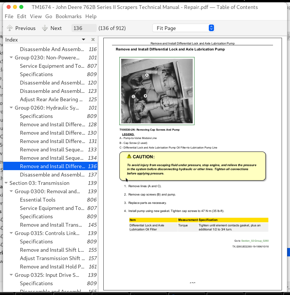
Remove and Install Differential Lock and Axle Lubrication Oil Filter................128
Remove and Install Differential Lock Solenoid Valve (S.N. -854650)................130
Remove and Install Differential Lock Solenoid Valve (S.N. 854651- )................131
Remove and Install Sequence Valve (S.N. -854650)................133
Remove and Install Sequence Valve (S.N. 854651- )................134
Remove and Install Differential Lock and Axle Lubrication Pump................136
Disassemble and Assemble Differential Lock and Axle Lubrication Pump................137
Section 03: Transmission................139
Group 0300: Removal and Installation................139
Essential Tools................806
Service Equipment and Tools................807
Specifications................809
Remove and Install Transmission................145
Group 0315: Controls Linkage................139
Specifications................809
Remove and Install Shift Lever Linkage................155
Adjust Transmission Shift Lever Linkage................157
Remove and Install Hold Pedal-Automatic Transmission................161
Group 0325: Input Drive Shafts and U-Joints................139
Specifications................809
Disassemble and Assemble Input Drive Shaft................165
Group 0350: Gears, Shafts, Bearings and Power Shift Clutch................139
Essential Tools................806
Service Equipment and Tools................807
Other Material................808
Specifications................809
Remove and Install Transmission Cover................171
Cross Section Transmission................172
Remove and Install Output Shaft................174
Install Wear Sleeve On Output Shaft................176
Remove And Install C1 Clutch Pack................177
Disassemble and Assemble C1 Clutch................178
Remove and Install Planetary Pack................183
Disassemble and Assemble Planetary Pack................185
Disassemble and Assemble C2 Clutch................197
Disassemble and Assemble Planetary Assembly................202
Remove and Install Drop Train Gears................206
Group 0360: Hydraulic System................139
Service Equipment and Tools................807
Other Material................808
Specifications................809
Disassemble and Assemble Torque Converter Clutch Modulating Control Valve................215
Remove and Install Suction Screen................217
Remove and Install Lube Relief Valve................218
Remove and Install Transmission Oil Filter................219
Disassemble and Assemble Transmission Oil Filter................221
Remove and Install Transmission Pump................222
Disassemble and Assemble Transmission Pump................224
Remove and Install Transmission Control Valve................225
Transmission Control Valve Mounting Plate and Gaskets................227
Transmission Control Valve Cross Section................228
Disassemble and Assemble Transmission Control Valve................230
Remove and Install Solenoid Valve Assembly................233
Disassemble and Assemble Solenoid Valve Assembly................234
Section 04: Engine................236
Group 0400: Removal and Installation................236
6081 John Deere Engine-Use CTM86................239
John Deere Engine Accessories-Starter Repair-Use CTM77................240
Essential Tools................806
Service Equipment and Tools................807
Other Material................808
Specifications................809
Remove and Install Engine................246
Remove and Install Rear Engine Mount Isolators................250
Remove and Install Front Engine Mount Isolators................252
Remove and Install Starter................254
Remove and Install Fan Belt Tightener................256
Remove and Install Engine Oil Pan................257
Remove Fuel Supply Pump................260
Test Fuel Supply Pump For Leaks................261
Disassemble Fuel Supply Pump................262
Inspect and Repair Fuel Supply Pump................264
Assemble Fuel Supply Pump................265
Install Fuel Supply Pump................266
Remove Fuel Injection Pump................267
Install Fuel Injection Pump................270
Remove Fuel Injection Nozzles................274
Diagnose Injection Nozzle Malfunction................277
Test Fuel Injection Nozzles................280
Perform Opening Pressure Test................281
Injection Nozzle Opening Pressure Specifications................809
Perform Nozzle Leakage Test................283
Perform Chatter and Spray Pattern Test................285
Disassemble Fuel Injection Nozzle................286
Clean and Inspect Fuel Injection Nozzle Assembly................289
Perform Nozzle Slide Test................290
Clean Spray Orifices................291
Inspect Nozzle Holder................292
Inspect Gland Nut................294
Assemble Fuel Injection Nozzle................295
Test and Adjust Injection Nozzle Opening Pressure................298
Inspect and Clean Cylinder Head Nozzle Bore................299
Inspect and Clean Nozzle Seating Surface................300
Install Fuel Injection Nozzle................301
Remove Turbocharger................306
Install Turbocharger................308
Remove, Inspect and Test Intake Manifold and Aftercooler................311
Assemble and Install Aftercooler and Intake Manifold................314
Remove and Install Exhaust Manifold................316
Section 05: Engine Auxiliary Systems................318
Group 0505: Cold Weather Starting Aids................318
Other Material................808
Specifications................809
Remove and Install Engine Coolant Heater................323
Remove and Install Starting Aid Nozzle................325
Remove and Install Starting Aid Solenoid................327
Group 0510: Cooling Systems................318
Essential Tools................806
Other Material................808
Specifications................809
Remove and Install Fan................333
Remove and Install Differential Lock and Axle Lubrication Oil Cooler................335
Remove and Install Radiator and Transmission Oil Cooler................336
Remove and Install Serpentine Belt................339
Group 0515: Speed Controls................318
Remove and Install Speed Control Linkage................342
Remove and Install Fuel Shutoff Solenoid................343
Group 0520: Intake System................318
Service Equipment and Tools................807
Other Material................808
Specifications................809
Remove and Install Air Cleaner................349
Remove and Install Pre-Cleaner................351
Test Air Intake System for Leaks................353
Remove and Install Air Filter Elements................354
Clean Dusty Primary Element................355
Clean Oily or Sooty Primary Element................356
Inspect Element................357
Group 0530: External Exhaust System................318
Remove and Install Muffler................360
Group 0560: External Fuel Supply Systems................318
Remove and Install Fuel Tank................364
Remove and Install Fuel Supply Pump................366
Remove and Install Water Separator Fuel Filter................367
Section 06: Torque Converter................368
Group 0641: Housing and Cover................368
Specifications................809
Remove and Install Torque Converter................371
Group 0651: Converter Turbine, Gears, and Shaft................368
Service Equipment and Tools................807
Other Material................808
Specifications................809
Disassemble and Assemble Torque Converter Drive................378
Install Wear Sleeve On Input Yoke................393
Disassemble and Assemble Torque Converter Housing................394
Section 07: Dampener Drive................404
Group 0752: Elements................404
Specifications................809
Remove and Install Dampener Drive................407
Section 09: Steering System................409
Group 0960: Hydraulic System................409
Service Equipment and Tools................807
Specifications................809
Remove and Install Steering Wheel................413
Remove and Install Steering Column Angle Adjustment Bracket................415
Disassemble and Assemble Steering Column................417
Remove and Install Steering Valve................420
Disassemble Steering Valve................422
Cross Section of Steering Valve................426
Assemble Steering Valve................428
Remove and Install Steering Cylinder................432
Disassemble and Assemble Steering Cylinder................434
Section 10: Service Brakes................436
Group 1011: Active Elements................436
Specifications................809
Inspect Tractor Brake Linings................439
Remove and Install Bowl Hydraulic Brakes (S.N. -854650)................441
Disassemble Bowl Hydraulic Brakes (S.N. -854650)................443
Assemble Bowl Hydraulic Brakes (S.N. -854650)................445
Bowl Brake Adjustment (S.N. -854650)................450
Burnish Bowl Brake Shoe Facings (S.N. -854650)................452
Remove and Install Bowl Hydraulic Brakes (S.N. 854651- )................453
Disassemble and Assemble Bowl Hydraulic Brakes (S.N. 854651-)................455
Burnish Bowl Brake Pad Facings (S.N. 854651-)................457
Group 1060: Hydraulic System................436
Other Material................808
Specifications................809
Bleed Brake Hydraulic System (S.N. -854650)................461
Bleed Brake Hydraulic System (S.N. 854651-)................463
Remove and Install Tractor and Bowl Brake Accumulator................465
Remove and Install Brake Valve (S.N. -854650)................467
Remove and Install Brake Valve (S.N. 854651-)................469
Remove and Install Brake Pedal (S.N. -854650)................471
Disassemble and Assemble Tractor and Bowl Brake Valve (S.N. -854650)................472
Disassemble Tractor and Bowl Brake Valve (S.N. 854651-)................474
Assemble Tractor and Bowl Brake Valve (S.N. 854651-)................477
Remove and Install Brake Priority Solenoid Valve (S.N. -854650)................480
Remove and Install Brake Priority Solenoid Valve (S.N. 854651- )................482
Remove and Install Secondary Brake Solenoid Valve (S.N. -854650)................484
Remove and Install Secondary Brake Solenoid Valve (S.N. 854651- )................485
Remove and Install Residual Check Valve (S.N. -854650)................487
Remove and Install Shuttle Valve (S.N. 854651- )................488
Section 11: Park Brake................490
Group 1111: Active Elements................490
Specifications................809
Remove and Install Park Brake Pads................493
Disassemble and Assemble Park Brake................495
Park Brake Adjustment................496
Group 1160: Hydraulic System................490
Specifications................809
Remove and Install Park Brake Release Solenoid Valve (S.N. -854650)................500
Remove and Install Park Brake Release Solenoid Valve (S.N. 854651- )................501
Section 13: Miscellaneous Vehicle................503
Group 1370: Central Lubrication Systems................503
Sliding Floor Linkage................505
Draft Frame................506
Oscillation Hitch and Steering Arm Pivots................507
Axle Outer Bearing................508
Section 16: Electrical Systems................509
Group 1671: Batteries, Supports and Cables................509
Service Equipment and Tools................807
Specifications................809
Handle Batteries Safely................514
Procedure for Testing Batteries................515
Checking Electrolyte Specific Gravity................516
Check Battery Electrolyte Level and Terminals................518
Using Booster Batteries-24 Volt System................521
Charge Battery................523
Remove and Install Batteries................524
Adding 12-Volt Accessories................526
Group 1672: Alternator, Regulator and Charging System Wiring................509
Alternators and Starting Motors-Use CTM77................528
Specifications................809
Remove and Install Alternator................530
Group 1673: Lighting System................509
Remove and Install Brake Light Switch................534
Remove and Install Turn Signal Flasher................536
Remove and Install Turn/Warning Light Switch................537
Remove and Install Work Light and Headlight Switches................538
Replacing Halogen Bulbs................539
Group 1674: Wiring Harness and Switches................509
Essential Tools................806
Remove and Install Park Brake Switch................543
Electrical Component Identification................544
Engine Harness (W2) Component Location................549
Tractor Harness (W3) Component Location................551
Side Console Harness (W5) and Relay Harness (W13) Component Location-Automatic Transmission................554
Side Console Harness (W10) Component Location-Manual Transmission................557
Automatic Transmission Harness (W6) and Solenoid Harness (W8) Component Location................558
Scraper Harness (W4) and Rear Frame Harness (W11) Component Location................559
Automatic Transmission Harness (W8) Component Location................561
Manual Transmission Harness (W7) and Solenoid Harness (W14) Component Location................562
Manual Transmission Control Harness (W9) Component Location................563
Replace DEUTSCHDEUTSCH is a trademark of the Deutsch Co. Connectors................510
Install DEUTSCHDEUTSCH is a trademark of the Deutsch Co. Contact................510
Replace WEATHER PACK WEATHER PACK is a trademark of Packard Electric. Connector................510
Install WEATHER PACK WEATHER PACK is a trademark of Packard Electric. Contact................510
Remove Connector Body from Blade Terminals................572
Group 1675: System Controls................510
Remove and Install Transmission Control Box-Automatic Transmission................574
Remove and Install Magnetic Pickup-Automatic Transmission................575
Remove and Install Transmission Control Valve Solenoids................576
Remove and Install Transmission Hold and Downshift Switches-Automatic Transmission................577
Remove and Install Transmission Controller................578
Section 17: Frame, Chassis or Supporting Structure................579
Group 1740: Frame Installation................579
Service Equipment and Tools................807
Specifications................809
Remove and Install Main Frame................583
Remove and Install Oscillation Hitch................589
Repair Oscillation Hitch................591
Welding Repair of Major Structure................592
Section 18: Operator’s Station................594
Group 1810: Operator Enclosure................594
Service Equipment and Tools................807
Specifications................809
Disassemble and Assemble Windshield Wiper................599
Adjust Windshield Wiper Park Position................601
Disassemble and Assemble Canopy With Roof and Panels................603
Remove and Install Windowpanes................605
Group 1821: Seat and Seat Belt................594
Other Material................808
Specifications................809
Disassemble and Assemble Seat................609
Disassemble Seat Pedestal................610
Assemble Seat Pedestal................612
Adjust Seat................614
Replace Seat Compressor Filter................615
Group 1830: Heating and Air Conditioning................594
Essential Tools................806
Service Equipment and Tools................807
Other Material................808
Specifications................809
Proper Refrigerant Handling................623
R134a Refrigerant Cautions................624
R134a Component Oil Charge................625
R134a Refrigerant Recovery, Recycling, and Charging Station Installation Procedure................627
Recover R134a System................629
Evacuate R134a System................631
Charge R134a System................634
Leak Testing................636
Remove and Install Compressor................637
Volumetric Efficiency Test................638
Shaft Seal Leak Test................640
Disassemble and Assemble Compressor Clutch-R134a................641
Check Clutch Hub Clearance-R134a................643
Inspect Compressor Manifold-R134a................644
Disassemble, Inspect and Assemble Compressor-R134a................645
Remove and Install Compressor Relief Valve-R134a................648
Add Refrigerant Oil to System-R134a................649
Remove and Install Temperature Control Switch................650
Adjust Temperature Control Switch................651
Expansion Valve Bench Test and Adjustment................653
Remove and Install High and Low Refrigerant Pressure Switches................655
Remove and Install Blower Motor................656
Disassemble and Assemble Heater................657
Section 21: Main Hydraulic System................659
Group 2160: Main Hydraulic System................659
Specifications................809
Remove and Install Main Hydraulic Pump................662
Main Hydraulic Pump Cross Section................664
Disassemble and Inspect Main Hydraulic Pump................666
Assemble Main Hydraulic Pump................676
Remove and Install Hydraulic Filter................685
Section 35: Scraper and Haulage Device................686
Group 3501: Blades or Cutting Edges................686
Service Equipment and Tools................807
Specifications................809
Remove and Install Cutting Edge................691
Adjust Cutting Edge Level................692
Apply Hard Surface Welding................694
Group 3540: Frames................686
Other Material................808
Specifications................809
Remove and Install Bowl................698
Repair Bowl................699
Remove and Install Draft Frame................700
Adjust Draft Frame to Bowl Pivot................701
Repair Draft Frame................702
Remove and Install Sliding Floor................703
Adjust Sliding Floor Rail Guide................707
Repair Sliding Floor................709
Remove and Install Ejector Gate................710
Ejector Gate Clearance Adjustment................715
Repair Ejector Gate................717
Group 3560: Hydraulic System................686
Other Material................808
Specifications................809
Remove and Install Bowl Control Valve................721
Disassemble Bowl Control Valve................725
Disassemble and Assemble Bowl Valve Ejector Gate and Sliding Floor Section................726
Disassemble and Assemble Bowl Valve Lift Section................729
Assemble Bowl Control Valve................732
Disassemble and Assemble Anti-Cavitation Valve................733
Remove and Install Bowl Lift Cylinders................734
Remove and Install Ejector Gate and Sliding Floor Cylinders................736
Disassemble and Assemble Ejector Gate Cylinder................738
Disassemble and Assemble Sliding Floor Cylinder................740
Section 36: Conveyor and Elevator Device................742
Group 3612: Conveyor or Mast................742
Essential Tools................806
Specifications................809
Remove and Install Elevator Chain................747
Install Seals-Sealed Elevator Chain (If Equipped)................750
Measure Chain Sag................751
Adjust Chain Sag................752
Adjust Elevator-to-Cutting Edge................754
Lubricate Non-Sealed Elevator Chain................755
Remove and Install Adjusting Idler................756
Disassemble and Assemble Adjusting Idler................757
Remove and Install Upper Idler................759
Repair Upper Idler................760
Remove and Install Lower Idler................763
Repair Lower Idler................765
Group 3615: Controls Linkage................742
Disassemble and Assemble Control Linkage................769
Group 3640: Frames................742
Specifications................809
Remove and Install Elevator Frame................773
Group 3650: Gearbox................742
Other Material................808
Specifications................809
Remove and Install Elevator Drive Case and Gearbox................778
Disassemble Elevator Drive Case................780
Clean and Inspect Parts................870
Assemble Elevator Drive Case................788
Disassemble and Assemble Elevator Gearbox Pinion Shaft................794
Disassemble and Assemble Elevator Gearbox Output Shaft................798
Group 3660: Hydraulic System................742
Essential Tools................806
Service Equipment and Tools................807
Other Material................808
Specifications................809
Remove and Install Elevator Charge Pump................810
Disassemble and Assemble Elevator Charge Pump................811
Serial Number Plate................813
Remove and Install Elevator Drive Pump................814
Remove and Install Elevator Drive Pump Shaft Seal................817
Disassemble Elevator Drive Pump................820
Assemble Drive Pump................837
Remove and Install Displacement Control Valve................856
Disassemble and Assemble Displacement Control Valve................857
Remove and Install Elevator Drive Motor................859
Disassemble Elevator Drive Motor................861
Inspect Parts................870
Lack of Lubrication................871
Abrasive Contamination................872
Cavitation................873
Excessive Oil Temperature................874
Improper Lubrication................875
Over Speeding................876
Inspect Shaft Seal................877
Inspect Thrust Plate................879
Inspection Piston Slipper................880
Inspect Piston Retainer................882
Inspect Cylinder Block................884
Inspect Bearing Block................885
Inspect Valve Plate................889
Inspect Bearing and Race................892
Inspect Servo Piston................893
Inspect Drive Shaft................894
Replace Cylinder Block Spring................895
Assemble Elevator Drive Motor................896
Section 99: Dealer Fabricated Tools................907
Group 9900: Dealer Fabricated Tools................907
DFRW20 Compressor Holding Fixture................909
John Deere Scrapers 762B Series II Service Repair Manual (TM1674)
![]()