
John Deere 35G Compact Excavator Operation and Test Service Manual (TM12891)

Complete Diagnostics, Operation and Test manual with electrical wiring diagrams for John Deere 35G Compact Excavator, with all the shop information to maintain, diagnose, and rebuild like professional mechanics.
John Deere 35G Compact Excavator workshop Operation and Test manual includes:
* Numbered table of contents easy to use so that you can find the information you need fast.
* Detailed sub-steps expand on repair procedure information
* Numbered instructions guide you through every repair procedure step by step.
* Troubleshooting and electrical service procedures are combined with detailed wiring diagrams for ease of use.
* Notes, cautions and warnings throughout each chapter pinpoint critical information.
* Bold figure number help you quickly match illustrations with instructions.
* Detailed illustrations, drawings and photos guide you through every procedure.
* Enlarged inset helps you identify and examine parts in detail.
TM12891 - John Deere 35G Compact Excavator Technical Manual - Operation and Test.pdf
TM12891 - John Deere 35G Compact Excavator Technical Manual - Operation and Test.epub
PRODUCT DETAILS:
Total Pages: 805 pages
File Format: PDF/EPUB/MOBI/AZW (PC/Mac/Android/Kindle/iPhone/iPad; bookmarked, ToC, Searchable, Printable)
Language: English
MAIN SECTIONS 35G (PIN: 1FF035GX**K270001—)
Foreword
Technical Information Feedback Form
General Information
Safety
Diagnostics
Engine Control Unit (ECU) Diagnostic Trouble Codes
Monitor Controller (DSZ) Diagnostic Trouble Codes
Operational Checkout Procedure
Operational Checkout Procedure
Engine
Theory of Operation
Diagnostic Information
Adjustments
Tests
Electrical System
System Information
System Diagrams
Sub-System Diagnostics
Monitor Operation
References
Power Train
Theory of Operation
Diagnostic Information
Hydraulic System
Theory of Operation
Diagnostic Information
Tests
Heating and Air Conditioning
Theory of Operation
Diagnostic Information
Tests
tm12891 - 35G Excavator
Table of Contents
Foreword
Technical Information Feedback Form
Section 9000: General Information
Group 01: Safety
Recognize Safety Information
Follow Safety Instructions
Operate Only If Qualified
Wear Protective Equipment
Avoid Unauthorized Machine Modifications
Control Pattern Selector—If Equipped
Add Cab Guarding for Special Uses
Inspect Machine
Stay Clear of Moving Parts
Avoid High-Pressure Fluids
Avoid High-Pressure Oils
Work In Ventilated Area
Prevent Fires
Prevent Battery Explosions
Handle Chemical Products Safely
Decommissioning — Proper Recycling and Disposal of Fluids and Components
Prepare for Emergencies
Clean Debris from Machine
Use Steps and Handholds Correctly
Start Only From Operator's Seat
Use and Maintain Seat Belt
Prevent Unintended Machine Movement
Avoid Work Site Hazards
Keep Riders Off Machine
Avoid Backover Accidents
Inspect and Maintain ROPS
Avoid Machine Tip Over
Use Special Care When Lifting Objects
Add and Operate Attachments Safely
Park and Prepare for Service Safely
Service Cooling System Safely
Remove Paint Before Welding or Heating
Make Welding Repairs Safely
Drive Metal Pins Safely
Section 9001: Diagnostics
Group 10: Engine Control Unit (ECU) Diagnostic Trouble Codes
Engine Control Unit (ECU) Diagnostic Trouble Codes
000029.08 - Spare Accelerator Sensor Error (Pulse Communication) (P1227) (0001D-08)
000091.02 - Accelerator Sensor Intermittent Failure (P0124) (0005B-02)
000091.03 - Acceleration Sensor Error (High Voltage) (P0123) (0005B-03)
000091.04 - Acceleration Sensor Error (Low Voltage) (P0122) (0005B-04)
000100.01 - Oil Pressure Descend Error (P1198) (00064-01)
000100.04 - Oil Pressure Switch Error (P1192) (00064-04)
000110.00 - Cooling Water Temperature Rise Alarm (Overheat) (P0217) (0006E-00)
000110.02 - Cooling Water Temperature Sensor Intermittent Failure (P0119) (0006E-02)
000110.03 - Cooling Water Temperature Sensor Error (High Voltage) (P0118) (0006E-03)
000110.04 - Cooling Water Temperature Sensor Error (Low Voltage) (P0117) (0006E-04)
000158.00 - Power Supply Voltage Error (High Voltage) (P0563) (0009E-00)
000158.01 - Power Supply Voltage Error (Low Voltage) (P0562) (0009E-01)
000167.01 - Charge Alarm (P1568) (000A7-01)
000167.04 - Charge Switch Error (P1562) (000A7-04)
000190.00 - Overspeed Error (P0219) (000BE-00)
000628.02 - ECU Internal Flash ROM Error (Checksum B) (P1605) (00274-02)
000628.02 - ECU Internal Flash ROM Error (Checksum C) (P1606) (00274-02)
000628.12 - ECU Internal Flash ROM Error (Checksum A) (P0605) (00274-0C)
000630.02 - ECU Internal EEPROM Error (Checksum) (P1601) (00276-02)
000630.12 - ECU Internal EEPROM Error (Read/Write Error) (P0601) (00276-0C)
000638.02 - Engine Error (P1214) (0027E-02)
000638.03 - Rack Actuator Error (High Current) (P1213) (0027E-03)
000638.04 - Rack Actuator Error (Low Current) (P1212) (0027E-04)
000638.07 - Rack Actuator Mechanical Failure (P1211) (0027E-07)
000639.12 - CAN Communication Error (U0001) (0027F-0C)
001078.04 - Speed Sensor Error (P0340) (00436-04)
001079.02 - Sensor 5 V Intermittent Failure (P1644) (00437-02)
001079.03 - Sensor 5 V Error (High Voltage) (P0643) (00437-03)
001079.04 - Sensor 5 V Error (Low Voltage) (P0642) (00437-04)
001136.01 - ECU Temperature Rise Alarm (P0634) (00470-00)
001136.02 - ECU Temperature Sensor Intermittent Failure (P1664) (00470-02)
001136.03 - ECU Temperature Sensor Error (High Voltage) (P0669) (00470-03)
001136.04 - ECU Temperature Sensor Error (Low Voltage) (P0668) (00470-04)
001210.03 - Rack Position Sensor Error (High Voltage) (P1203) (004BA-03)
001210.04 - Rack Position Sensor Error (Low Voltage) (P1202) (004BA-04)
001485.04 - Main Relay Error (P0686) (005CD-04)
522241.02 - Rack Actuator Relay Intermittent Failure (P1224) (7F801-02)
522241.03 - Rack Actuator Relay Error B (P1223) (7F801-03)
522241.04 - Rack Actuator Relay Error A (P1222) (7F801-04)
522242.02 - CSD Solenoid Valve Intermittent Failure (P1244) (7F802-02)
522242.03 - CSD Solenoid Valve Error B (P1243) (7F802-03)
522242.04 - CSD Solenoid Valve Error A (P1242) (7F802-04)
522243.02 - Start Assist Relay Intermittent Failure (P1234) (7F803-02)
522243.03 - Start Assist Relay Error B (P1233) (7F803-03)
522243.04 - Start Assist Relay Error A (P1232) (7F803-04)
522251.03 - EGR Valve Error B (Step Motor A-Phase) (P1403) (7F80B-03)
522251.04 - EGR Valve Error A (Step Motor A-Phase) (P1402) (7F80B-04)
522252.03 - EGR Valve Error B (Step Motor B-Phase) (P1413) (7F80C-03)
522252.04 - EGR Valve Error A (Step Motor B-Phase) (P1412) (7F80C-04)
522253.03 - EGR Valve Error B (Step Motor C-Phase) (P1423) (7F80D-03)
522253.04 - EGR Valve Error A (Step Motor C-Phase) (P1422) (7F80D-04)
522254.03 - EGR Valve Error B (Step Motor D-Phase) (P1433) (7F80E-03)
522254.04 - EGR Valve Error A (Step Motor D-Phase) (P1432) (7F80E-04)
522314.00 - Abnormal Water Temperature (P1217) (7F84A-00)
522323.00 - Air Cleaner Clogging Alarm (P1101) (7F853-00)
522329.00 - Oil/Water Separator Alarm (P1151) (7F859-00)
522402.04 - Spare Speed Sensor Error (P1340) (7F8A2-04)
522727.12 - ECU Internal Sub CPU Error A (P1610) (7F9E7-0C)
522727.12 - ECU Internal Sub CPU Error B (P1611) (7F9E7-0C)
522727.12 - ECU Internal Sub CPU Error C (P1612) (7F9E7-0C)
522728.12 - ECU Internal Map Format Error (P1620) (7F9E8-0C)
Group 30: Monitor Controller (DSZ) Diagnostic Trouble Codes
Monitor Controller (DSZ) Diagnostic Trouble Codes
E:1100 - Engine Trouble Alarm
W:1100 - Engine Warning
W:1102 - Exhaust Filter Regeneration Request
W:1103 - Exhaust Filter Regeneration Inhibited Alarm
W:1104 - Intermediate Gas Temperature Sensor Error
W:1105 - Exhaust Filter Differential Pressure Sensor Error
W:1106 - Inlet Port Gas Temperature Sensor Error
W:1107 - Engine Injection Pressure Sensor Error
W:1108 - Exhaust Filter Gas Inlet Air Pressure Sensor Error
W:1109 - Engine Inlet Air Piping Abnormal Temperature
W:1110 - Air Heat Relay Error
W:1111 - Exhaust Filter Manual Regeneration Inhibited Alarm
W:1206 - Air Filter Restriction Alarm
W:1207 - Coolant Temperature Sensor Error
W:1208 - Engine Speed Sensor Error
W:1209 - Atmospheric Pressure Sensor Error
W:1210 - Water Separator Alarm
W:1211 - Ambient Air Temperature Sensor Error
W:1303 - Combustion Temperature Sensor Error
W:1304 - Engine Control Dial Error (CAN Signal)
W:1310 - CAN Communication Error
W:2201 - Overheat Alarm
W:2202 - Engine Oil Pressure Alarm
W:2304 - Fuel Sensor Error
W:2306 - Boom Bottom Pressure Sensor Error
W:2307 - Engine Control Dial Error (Analog Signal)
W:2310 - EEPROM Error
Section 9005: Operational Checkout Procedure
Group 10: Operational Checkout Procedure
Operational Checkout
Section 9010: Engine
Group 05: Theory of Operation
Yanmar Engine
Engine Fuel System Component Location
Engine Cooling System Component Location
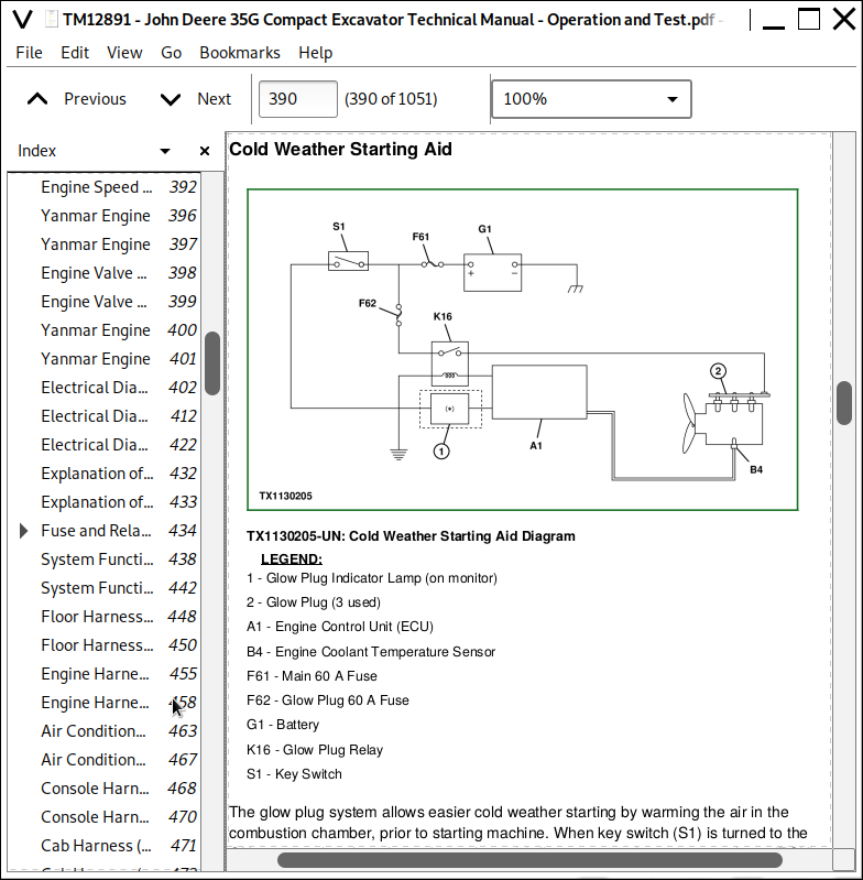
Cold Weather Starting Aid
Engine Speed Control System Operation
Group 15: Diagnostic Information
Yanmar Engine
Group 20: Adjustments
Engine Valve Lash (Clearance) Check and Adjustment
Group 25: Tests
Yanmar Engine
Section 9015: Electrical System
Group 05: System Information
Electrical Diagram Information
Group 10: System Diagrams
Explanation of Wire Markings
Fuse and Relay Specifications
System Functional Schematic, Wiring Diagrams, and Component Locations Master Legend
System Functional Schematic
Floor Harness (W1) Component Location
Floor Harness (W1) Wiring Diagram
Engine Harness (W2) Component Location
Engine Harness (W2) Wiring Diagram
Air Conditioner Harness (W3) Component Location
Air Conditioner Harness (W3) Wiring Diagram
Console Harness (W4) Component Location
Console Harness (W4) Wiring Diagram
Cab Harness (W5) Component Location
Cab Harness (W5) Wiring Diagram
Auto-Shutdown Harness (W6) Component Location
Auto-Shutdown Harness (W6) Wiring Diagram
Auxiliary Function Lever Harness (W7) Component Location
Auxiliary Function Lever Harness (W7) Wiring Diagram
Air Conditioner Compressor Harness (W8) Component Location
Air Conditioner Compressor Harness (W8) Wiring Diagram
Boom Work Light Harness (W9) Component Location
Boom Work Light Harness (W9) Wiring Diagram
Canopy Work Light Harness (W13) Component Location
Canopy Work Light Harness (W13) Wiring Diagram
Angle Blade Floor Harness (W14) Component Location
Angle Blade Floor Harness (W14) Wiring Diagram
Angle Blade Solenoid Harness (W15) Component Location
Angle Blade Solenoid Harness (W15) Wiring Diagram
Windshield Wiper Extension Harness (W16) Component Location
Windshield Wiper Extension Harness (W16) Wiring Diagram
Windshield Wiper Harness (W17) Component Location
Windshield Wiper Harness (W17) Wiring Diagram
Group 15: Sub-System Diagnostics
Controller Area Network (CAN) Theory of Operation
Starting and Charging Circuit Theory of Operation
Auto-Shutdown Circuit Theory of Operation
Engine Control Unit (ECU) Circuit Theory of Operation
Monitor Controller (DSZ) Circuit Theory of Operation
Pilot Shutoff Circuit Theory of Operation
Travel Speed Control and Alarm Circuit Theory of Operation
Windshield Wiper and Washer Circuit Theory of Operation
Lighting Circuit Theory of Operation
Heating and Air Conditioning Control Circuit Theory of Operation
Auxiliary Function Control Lever Circuit Theory of Operation
Group 16: Monitor Operation
Service Menu
Monitoring
Setting
Trouble Code Record
Group 20: References
Reading Diagnostic Trouble Codes With Monitor Display
Service ADVISOR™ Diagnostic Application
Service ADVISOR™ Connection Procedure
Reading Diagnostic Trouble Codes with Service ADVISOR™ Diagnostic Application
Fuse Test
Relay Test
Pressure Sensor Test
Solenoid Test
Temperature Sensor Test
Alternator Test
Electrical Component Checks
Battery Remove and Install
Monitor Controller (DSZ) Remove and Install
Monitor Controller (DSZ) Replacement Calibration
Engine Control Unit (ECU) Remove and Install
Engine Control Unit (ECU) Replacement Calibration
Fuel Pump Replacement Calibration
Yanmar Display Calibration Values Test
Air Conditioner Controller (ACF) Remove and Install
Key Switch Remove and Install
Engine Speed Dial Remove and Install
Travel Alarm Remove and Install
Disconnect Tab Retainer Connectors
Disconnecting Spring Wire Clip Connectors
Replace DEUTSCH™ Connectors
Replace DEUTSCH™ Rectangular or Triangular Connectors
Install DEUTSCH™ Contact
Replace WEATHER PACK™ Connector
Install WEATHER PACK™ Contact
Replace (Pull Type) Metri-Pack™ Connectors
Replace (Push Type) Metri-Pack™ Connectors
Replace CINCH™ Connectors
Install CINCH™ Contact
Repair 32 and 48 Way CINCH™ Connectors
Remove Connector Body from Blade Terminals
Section 9020: Power Train
Group 05: Theory of Operation
Track Adjuster and Recoil Spring Operation
Travel Gear Case Operation
Group 15: Diagnostic Information
Noisy or Loose Track Chain
Tight Track Chain
Frequent Track Chain Sag Adjustment Required
Excessive Oil Leakage From Front Idler, Track Rollers, or Carrier Rollers
Bent Track Shoes (Steel Track Only)
“Popping” of Track
Cracked Track Link
Chipped Link Rails
Individual Undercarriage Component Wear
Measure Swing Bearing Wear
Section 9025: Hydraulic System
Group 05: Theory of Operation
Hydraulic System Operation
Pilot System Operation
Pilot Pump and Filter Operation
Solenoid Valve Manifold Operation
Pilot Shutoff Solenoid Valve Operation
Travel Speed Solenoid Valve Operation
Pilot Pressure Regulating Valve Operation
Pilot Control Valve Operation
Control Lever Pattern Selector Operation
Travel Pilot Control Valve Operation
Pilot Operation of Control Valve Operation
Hydraulic Pump 1 and 2 Operation
Hydraulic Pump Regulator Operation
Hydraulic Pump 3 Operation
Air Conditioner Torque Control Solenoid Valve Operation—If Equipped
Control Valve Operation
Control Valve Check Valves Operation
Main Relief Valve Operation
Circuit Relief and Anticavitation Valve Operation
Swing Boom Make-Up Valve Operation
Flow Combiner Valve Operation
Auxiliary Function Control Valve Operation
Boom Reduced Leakage Valve Operation
Arm Regenerative Valve Operation
Swing Reduction Gear Case Operation
Swing Motor Operation
Swing Motor Crossover Relief Valve Operation
Swing Motor Crossover Relief Valve Cushion Valve Operation
Swing Motor Make-Up Check Valve Operation
Swing Motor Park Brake Release Circuit Operation
Center Joint Operation
Travel Motor and Park Brake Valve Operation
Travel Motor Speed Circuit Operation
Blade Circuit Operation
Angle Blade Circuit Operation—If Equipped
Angle Blade Solenoid Valve Operation—If Equipped
Auxiliary Selector Valve Operation
Hydraulic Cylinder Operation
Return Filter Operation
Group 15: Diagnostic Information
All Hydraulic Functions Slow
Hydraulic Oil Overheats
No Hydraulic Functions
Poor Combined Operation
All Functions Cannot Be Operated
Function Does Not Stop When Control Lever Released
Some Functions Cannot Be Operated, All Others Are Normal
Functions Move in Opposite Direction
Arm and Boom Functions Do Not Operate or Do Not Operate as Expected
All Dig Functions Slow or No Power
Some Dig Functions Slow (Not All)
Load Drifts Down When Control Lever is in Neutral Position
Load Falls When Control Valve is Actuated to Raise Load With Engine Running at Slow Idle
Arm In Speed Slow
Swing Speed Slow in Both Directions
Swing Speed Slow or Does Not Operate in One Direction
Upperstructure Drift With Swing Valve in Neutral
Swing Function Does Not Operate
Travel Park Brakes Do Not Apply
Track Will Not Move in One Direction
Track Will Not Move in Either Direction
Machine Mistracks at All Speeds in Both Directions
Machine Mistracks in High Speed Only, or Mistracks One Direction in High Speed and the Other Direction in Low Speed
Slow Travel Speed or Low Power
Travel Speed Does Not Change to Slow Speed
Combined Travel and Dig Functions Slow or No Power
Travel is “Jerky”
Machine Will Not Hold Back and Park Brakes Engage and Disengage When Traveling Down an Incline
Machine Will Not Turn Smoothly in One Direction or Park Brake Grabs
Swing Boom Does Not Move or Moves Slowly
Blade Does Not Move or Moves Slowly
Pump 1, Pump 2, Pump 3, and Pilot Pump Line Identification
Control Valve Line Identification
Pilot Control Lever Pattern Selector Valve Line Connection
Swing Motor Line Identification
Travel System Component Location
Travel Hydraulic System Line Connection
Blade System Component Location
Blade Hydraulic System Line Connection
Hydraulic System Schematic
Hydraulic System Component Location
Hydraulic System Pilot Line Connection
Hydraulic System Main Line Connection
Angle Blade Component Location—If Equipped
Angle Blade Hydraulic System Line Connection—If Equipped
Group 25: Tests
JT05800 Digital Thermometer Installation
JT02156A Digital Pressure and Temperature Analyzer Installation
General Hydraulic Oil Cleanup Procedure
Hydraulic Component Failure Cleanup Procedure
Hydraulic Oil Tank Pressure Release Procedure
Hydraulic System Warm-Up Procedure
Pilot Pressure Regulating Valve Test and Adjustment
Control Valve Spool Pilot Actuating Pressure Test
Hydraulic Pump 1, 2, and 3 Main Relief Valve Test and Adjustment
Circuit Relief and Anticavitation Valve Test and Adjustment
Swing Motor Crossover Relief Valve Test and Adjustment
Hydraulic Pump Flow Test
Swing Motor Leakage Test
Travel Motor Leakage Test
Air Conditioner Torque Control Solenoid Valve Test
Cylinder Drift Test—Boom, Arm, Bucket, and Blade
Section 9031: Heating and Air Conditioning
Group 05: Theory of Operation
Air Conditioning System Cycle of Operation
Group 15: Diagnostic Information
Air Conditioning System Does Not Operate
No Air Flow From Heater and Air Conditioner Vents
Air Conditioning Does Not Cool Interior of Cab
Air Conditioning Runs Constantly, Too Cold
Interior Windows Continue to Fog Using Air Conditioner
Heater System Does Not Operate
Heater Does Not Warm Interior of Cab
Interior Windows Continue to Fog Using Heater
Heater and Air Conditioner Component Location
Group 25: Tests
Refrigerant Cautions and Proper Handling
Heater and Air Conditioner Operational Checks
Refrigerant Leak Test
Air Conditioner Compressor Clutch Test
Refrigerant Hoses and Tubing Inspection
Air Conditioner Compressor Belt Check
R134a Air Conditioning System Test
Operating Pressure Diagnostic Chart
John Deere 35G Compact Excavator Operation and Test Service Manual (TM12891)
![]()