
John Deere 250D and 300D Articulated Dump Truck Service Manual - TM1160 (Operation & Test)

John Deere 250D and 300D Articulated Dump Truck Service Manual - TM1160 (Operation & Test)
TM1160 - John Deere 250D and 300D Articulated Dump Truck Technical Manual (Operation & Test).PDF
Complete official service manual (Operation & Test) with Electrical Wiring Diagrams for John Deere 250D and 300D Articulated Dump Truck, with all the shop information to maintain, diagnostic, repair, refurbishrebuild like professional mechanics.
John Deere 250D and 300D Articulated Dump Truck (ADT) workshop service & repair manual includes:
* Numbered table of contents easy to use so that you can find the information you need fast.
* Detailed sub-steps expand on repair procedure information
* Numbered instructions guide you through every repair procedure step by step.
* Troubleshooting and electrical service procedures are combined with detailed wiring diagrams for ease of use.
* Notes, cautions and warnings throughout each chapter pinpoint critical information.
* Bold figure number help you quickly match illustrations with instructions.
* Detailed illustrations, drawings and photos guide you through every procedure.
* Enlarged inset helps you identify and examine parts in detail.
Total Pages: 936 pages
File Format: PDF (bookmarked, Searchable, Printable, high quality)
Language: English
MAIN SECTIONS
Foreword
Technical Information Feedback Form
General Information
Safety
Diagnostic Trouble Codes (DTCs)
Chassis Control Unit (CCU) Diagnostic Trouble Codes
Engine Control Unit (ECU) Diagnostic Trouble Codes
Monitor Display Unit (MDU) Diagnostic Trouble Codes
Output Expansion Unit (OEU) Diagnostic Trouble Codes
Sealed Switch Module (SSM) Diagnostic Trouble Codes
Transmission Control Unit (TCU) Diagnostic Trouble Codes
Operational Checkout Procedure
Operational Checkout Procedure
Engine
Theory of Operation
Diagnostic Information
Tests
Electrical System
System Information
System Diagrams
Sub-System Diagnostics
References
Power Train
Theory of Operation
Diagnostic Information
Tests
Pneumatic System
Theory of Operation
Diagnostic Information
Tests
Hydraulic System
Theory of Operation
Diagnostic Information
Tests
Heating and Air Conditioning
Theory of Operation
Diagnostic Information
Tests
tm1160 - 250D and 300D Articulated Dump Truck (609166-626760)
Table of Contents
Foreword
Technical Information Feedback Form
Section 9000: General Information
Group 01: Safety
Recognize Safety Information
Follow Safety Instructions
Operate Only If Qualified
Wear Protective Equipment
Avoid Unauthorized Machine Modifications
Inspect Machine
Stay Clear of Moving Parts
Avoid High-Pressure Fluids
Avoid High-Pressure Oils
Beware of Exhaust Fumes
Prevent Fires
Prevent Battery Explosions
Handle Chemical Products Safely
Dispose of Waste Properly
Prepare for Emergencies
Use Steps and Handholds Correctly
Start Only From Operator's Seat
Use and Maintain Seat Belt
Prevent Unintended Machine Movement
Avoid Work Site Hazards
Keep Riders Off Machine
Avoid Backover Accidents
Avoid Machine Tip Over
Operating on Slopes
Operating or Traveling on Public Roads
Inspect and Maintain ROPS
Add and Operate Attachments Safely
Prevent Unintended Detonation of Explosive Devices
Park and Prepare for Service Safely
Service Tires Safely
Service Cooling System Safely
Remove Paint Before Welding or Heating
Make Welding Repairs Safely
Drive Metal Pins Safely
Section 9001: Diagnostic Trouble Codes (DTCs)
Group 10: Chassis Control Unit (CCU) Diagnostic Trouble Codes
Diagnostic Trouble Code (DTC) Quick Reference List—Chassis Control Unit (CCU)
008000.05 - Headlight Dip Open Circuit
008000.06 - Headlight Dip Short Circuit
008000.18 - Headlight Dip Less Than Normal Current
008001.05 - Headlight Bright Open Circuit
008001.06 - Headlight Bright Short Circuit
008001.18 - Headlight Bright Less Than Normal Current
008002.00 - System Air Pressure Voltage Too High
008002.01 - System Air Pressure Voltage Too Low
000046.03 - Pneumatic Pressure Sensor Voltage High
008003.00 - Start Signal Voltage Too High
008004.05 - Reverse Open Circuit
008004.06 - Reverse Short Circuit
008004.18 - Reverse Less Than Normal Current
008005.00 - Rear Two Speed Switch Voltage Too High
008006.00 - Middle Two Speed Switch
008007.05 - Rear Wiper LO Speed Open Circuit
008007.06 - Rear Wiper LO Speed Short Circuit
008007.18 - Rear Wiper Lo Speed Less Than Normal Current
008008.00 - Scraper Dash Switch Voltage Too High
008009.01 - Pressure Two Speed Switch Voltage Too High
008010.05 - Front Wiper LO Speed Open Circuit
008010.06 - Front Wiper LO Speed Short Circuit
008010.18 - Front Wiper Lo Speed Less Than Normal Current
008011.00 - Battery Voltage Too High
008011.01 - Battery Voltage Too Low
008012.00 - Horn Switch Voltage Too High
008013.05 - Park Lights Open Circuit
008013.06 - Park Lights Short Circuit
008013.18 - Park Lights Less Than Normal Current
008014.01 - Ignition Supply via Fuse 25 Voltage Too Low
008015.05 - Work Lights Open Circuit
008015.06 - Work Lights Short Circuit
008015.18 - Work Light Less Than Normal Current
008016.01 - Ignition Supply via Fuse 26 Voltage Too Low
008017.01 - Brake Light Switch Voltage Too Low
008018.03 - IDL Solenoid or Bin Pressure Reduction Solenoid Voltage Too High
008018.05 - IDL Solenoid or Bin Pressure Reduction Solenoid Open Circuit or Short Circuit
008019.00 - Bonnet Fan Temp Switch Voltage Too High
008021.00 - Left Height Position Sensor Voltage Too High
008021.01 - Left Height Position Sensor Voltage Too Low
008022.01 - Hazard Dash Switch Voltage Too Low
008023.00 - Right Height Position Sensor Voltage Too High
008023.01 - Right Height Position Sensor Voltage Low
008024.03 - Bin Lever Latch or Pneumatic Blow Off Solenoid Voltage Too High
008024.05 - Bin Lever Latch or Pneumatic Blow Off Solenoid Voltage Too Low
008025.00 - Artic Angle Position Sensor Voltage Too High
008025.01 - Artic Angle Position Sensor Voltage Too Low
008026.00 - Bin Position Sensor Voltage Too High
008026.01 - Bin Position Sensor Voltage Too Low
008027.03 - Rear Wiper High Speed Voltage Too High
008027.05 - Rear Wiper High Speed Open Circuit or Short Circuit
008028.00 - Bin Lever Position Sensor Voltage Too High
008028.01 - Bin Lever Position Sensor Voltage Too Low
008030.01 - Park Brake Dash Switch Voltage Too Low
008031.00 - Front Two Speed Switch Voltage Too High
008032.03 - Flashing Beacon Light or Horn Voltage Too High
008032.05 - Flashing Beacon Light or Horn Open Circuit or Short Circuit
008033.00 - Aircon Evaporator Temperature Voltage Too High
008033.01 - Aircon Evaporator Temperature Voltage Too Low
008034.00 - Wet Disk Brake Temperature Voltage Too High
008034.01 - Wet Disk Brake Temperature Voltage Too Low
008035.00 - Cab Temperature Voltage Too High
008035.01 - Cab Temperature Voltage Too Low
008036.00 - 5-Volt Supply to Bin and Articulation Position Sensors Too High
008036.01 - 5-Volt Supply to Bin and Articulation Position Sensors Too High
008037.00 - 5-Volt Supply to Bin Sensors Too High
008037.01 - 5-Volt Supply to Bin Sensors Too Low
008038.01 - Ignition Power via Fuse 27 Voltage Too Low
008039.01 - Ignition Power via Fuse 28 Voltage Too Low
008040.00 - Alternator Voltage via Fuse 29 Too High
008040.01 - Alternator Voltage via Fuse 29 Too Low
008041.03 - Artic Reverse Light or Rear Washer Pump Voltage Too High
008041.05 - Artic Reverse Light or Rear Washer Pump Open Circuit or Short Circuit
008042.03 - Recirculation Flap or Aircon Clutch Solenoid Voltage Too High
008042.05 - Recirculation Flap or Aircon Clutch Solenoid Open Circuit or Short Circuit
008043.05 - Bin Up Solenoid Open Circuit
008043.06 - Bin Up Solenoid Short Circuit
008044.03 - Engine Running or Brake Light Output Voltage Too High
008044.05 - Engine Running or Brake Light Open Circuit or Short Circuit
008045.03 - Left Indicator Light or Right Indicator Light Voltage Too High
008045.05 - Left Indicator Light or Right Indicator Light Open Circuit or Short Circuit
008046.03 - Front Wiper Hi Speed or Front Washer Pump Voltage Too High
008046.05 - Front Wiper Hi Speed or Front Washer Pump Open Circuit or Short Circuit
008047.03 - Mirror Heating or Hydraulic Cut Solenoid Voltage Too High
008047.05 - Mirror Heating or Hydraulic Cut Solenoid Open Circuit
008048.03 - Bin Down Solenoid Open Circuit
008048.05 - Bin Down Solenoid Short Circuit
008048.06 - Bin Down Solenoid Short to Ground
008049.03 - Park Brake Solenoid Voltage Too High
008049.05 - Park Brake Solenoid Open Circuit or Short Circuit
008050.00 - Hydraulic Temperature Sensor Voltage Too High
008050.01 - Hydraulic Temperature Sensor Voltage Too Low
008051.01 - Ignition Power Voltage via Fuse 30 Too Low
008052.01 - Ignition Power Voltage via Fuse 31 Too Low
008100.31 - Boost Pressure Protection is Activated
008101.31 - Free Wheeling Event Detected
008102.31 - Engine is Idling for More than 20 Minutes
008103.31 - Engine RPM Exceeded Allowable Limit
008104.31 - Output Shaft Speed Exceeded Allowable Limit
008106.31 - Harsh Braking Detected
008107.31 - Engine Coolant Temperature Too High
008108.31 - Engine Oil Pressure Too Low
008109.31 - Transmission Sump Temperature Too High
008110.31 - TCU Calibration Mismatch
008111.31 - Park Brake Burnout Event Detected
008113.31 - Hydraulic Temperature Too High
008114.31 - Wet Disk Brake Temperature Too High
008116.31 - Tire Speed Limitation Exceeded
008119.31 - Unexpected Bin (Dump Body) Direction
Group 20: Engine Control Unit (ECU) Diagnostic Trouble Codes
Diagnostic Trouble Code (DTC) Quick Reference List—Engine Control Unit (ECU)
000091.08 - Throttle Signal Abnormal Frequency
000523.09 - Current Gear Message Not Received or Timeout
Group 30: Monitor Display Unit (MDU) Diagnostic Trouble Codes
Diagnostic Trouble Code (DTC) Quick Reference List—Monitor Display Unit (MDU)
000237.13 - VIN Mismatch between MDU and CCU
000628.13 - MDU Controller is in Bootmode
000630.13 - EOL Not Programmed Correctly
000639.19 - Loss of All CAN Messages
000830.00 - Fuel Sensor Above Normal
000830.01 - Fuel Sensor Below Normal
002000.19 - Loss of ECU CAN Messages
002003.19 - Loss of TCU CAN Messages
002033.19 - Loss of CCU CAN Messages
002049.19 - Loss of OEU CAN Messages
002064.19 - Loss of OBW Can Messages
002140.19 - Loss of SSM CAN Messages
002251.19 - Loss of MMU CAN Messages
Group 40: Output Expansion Unit (OEU) Diagnostic Trouble Codes
Diagnostic Trouble Code (DTC) Quick Reference List—Output Expansion Unit (OEU)
009001.05 - Blower Speed 3 Open Circuit
009001.06 - Blower Speed 3 Short Circuit
009001.18 - Blower High Speed Less Than Normal Current
009002.05 - Blower Speed 2 Open Circuit
009002.06 - Blower Speed 2 Short Circuit
009002.18 - Blower Medium Speed Less Than Normal Current
009004.05 - Blower Speed 1 Open Circuit
009004.06 - Blower Speed 1 Short Circuit
009004.18 - Blower Speed 1 Less Than Normal Current
009005.05 - Bonnet Fan 2 Open Circuit
009005.06 - Bonnet Fan 2 Short Circuit
009005.18 - Bonnet Fan 2 Less Than Normal Current
009006.01 - Ignition Supply Voltage via Fuse 18 Too Low
009007.05 - JD Starter Open Circuit
009007.06 - JD Starter Short Circuit
009007.18 - JD Starter Less Than Normal Current
009008.01 - Ignition Supply Voltage via Fuse 19 Too Low
009009.03 - Gear Hold Voltage Too High
009009.05 - Gear Hold Open Circuit or Short Circuit
009010.03 - Green or Yellow Load Light Short to Power
009010.05 - Green or Yellow Load Light Open Circuit
009011.03 - Automatic Neutral or Pre-Select 2nd Gear Voltage Too High
009011.05 - Automatic Neutral or Pre-Select 2nd Gear Open Circuit or Short Circuit
009012.05 - Load Light Red or Laden-Unladen Open Circuit or Short Circuit
009013.01 - Ignition Power Voltage via Fuse 20 Too Low
009014.01 - Ignition Power Voltage via Fuse 21 Too Low
009015.00 - Alternator Voltage Via Fuse 22 Too High
009015.01 - Alternator Voltage Via Fuse 22 Too Low
009017.03 - Heater Valve Voltage Too High
009017.05 - Heater Valve Open Circuit or Short Circuit
009018.05 - Engine Cooling Fan Open Circuit
009018.06 - Engine Cooling Fan Short to Ground
009019.03 - Fan Cut Solenoid Voltage Too High
009019.05 - Fan Cut Solenoid Open Circuit or Short Circuit
009021.03 - Left Strut Up/Down Solenoid Short to Power
009021.05 - Left Strut Up/Down Solenoid Open Circuit
009022.03 - Middle-Demist Actuator or Feet Actuator Voltage Too High
009022.05 - Middle-Demist Actuator or Feet Actuator Open Circuit or Short Circuit
009024.03 - Right Strut Up/Down Solenoid Voltage High
009024.05 - Right Strut Up/Down Solenoid Current Low
009025.01 - Ignition Power Voltage via Fuse 23 Too Low
009026.01 - Ignition Power Voltage via Fuse 24 Too Low
Group 50: Sealed Switch Module (SSM) Diagnostic Trouble Codes
Diagnostic Trouble Code (DTC) Quick Reference List—Sealed Switch Module (SSM)
000629.12 - Sealed Switch Module Watchdog Timeout
000639.09 - Sealed Switch Module No CAN Message
000639.12 - Sealed Switch Module CAN Lost Message
000639.13 - Sealed Switch Module CAN Warning Limit Exceeded
000639.19 - Sealed Switch Module CAN Bus Off
002033.09 - CCU CAN Communication Fault
523523.10 - Front Wiper Switch Stuck
523524.10 - Retarder Increase Switch Stuck
523525.10 - Retarder Decrease Switch Stuck
523526.10 - Headlights Switch Stuck
523527.10 - Beacon Light Switch Stuck
523528.10 - Bin Limits Switch Stuck
523529.10 - Temperature Control Down Switch Stuck
523530.10 - Temperature Control Up Switch Stuck
523531.10 - Air Flow Control Switch Stuck
523532.10 - Two-Speed Switch Stuck
523533.10 - Range Hold Switch Stuck
523534.10 - Inter-Axle Lock Switch Stuck
523535.10 - Differential Lock Switch Stuck
523536.10 - Blower Speed Switch Stuck
523537.10 - Recirculating Air Switch Stuck
523538.10 - Air Conditioning Switch Stuck
523607.10 - Bin Function Switch Stuck
523608.10 - Side Mirror Heater Switch Stuck
523609.10 - Work Lights Switch Stuck
523610.10 - Rear Wiper Switch Stuck
Group 60: Transmission Control Unit (TCU) Diagnostic Trouble Codes
Diagnostic Trouble Code (DTC) Quick Reference List—Transmission Control Unit (TCU)
005017.03 - Retarder Temperature Sensor Open Circuit
005017.04 - Retarder Temperature Sensor Short to Ground
005018.03 - Sump Temperature Sensor Open Circuit
005018.04 - Sump Temperature Sensor Short to Ground
005021.03 - A Clutch Solenoid Short to Power
005021.04 - A Clutch Solenoid Short to Ground
005021.05 - A Clutch Solenoid Open Circuit
005022.03 - B Clutch Solenoid Short to Power
005022.04 - B Clutch Solenoid Short to Ground
005022.05 - B Clutch Solenoid Open Circuit
005023.03 - C Clutch Solenoid Short to Power
005023.04 - C Clutch Solenoid Short to Ground
005023.05 - C Clutch Solenoid Open Circuit
005024.03 - D Clutch Solenoid Short to Power
005024.04 - D Clutch Solenoid Short to Ground
005024.05 - D Clutch Solenoid Open Circuit
005025.03 - E Clutch Solenoid Short to Power
005025.04 - E Clutch Solenoid Short to Ground
005025.05 - E Clutch Solenoid Open Circuit
005026.03 - F Clutch Solenoid Short to Power
005026.04 - F Clutch Solenoid Short to Ground
005026.05 - F Clutch Solenoid Open Circuit
005027.03 - G Clutch Solenoid Short to Power
005027.04 - G Clutch Solenoid Short to Ground
005027.05 - G Clutch Solenoid Open Circuit
005028.03 - WK Clutch Solenoid Short to Power
005028.04 - WK Clutch Solenoid Short to Ground
005028.05 - WK Clutch Solenoid Open Circuit
005039.03 - Shifter Lock Solenoid Short to Power
005039.04 - Shifter Lock Solenoid Short to Ground
005039.05 - Shifter Lock Solenoid Open Circuit
005044.02 - D1 Clutch Solenoid Resistance
005044.03 - D1 Clutch Solenoid Short to Power
005044.04 - D1 Clutch Solenoid Short to Ground
005044.05 - D1 Clutch Solenoid Open Circuit
005045.03 - Retarder Proportional Solenoid Short to Power
005045.04 - Retarder Proportional Solenoid Short to Ground
005045.05 - Retarder Proportional Solenoid Open Circuit
005046.02 - Transmission Shift Control Signal Malfunction
005049.02 - Hour Counter Malfunction
005051.02 - TCU Memory Malfunction
005052.11 - TCU System Malfunction
005055.02 - CAN Data Link Malfunction
005056.04 - Retarder On Solenoid Short to Ground
005056.05 - Retarder On Solenoid Open Circuit
005058.02 - Output Speed Sensor Signal Malfunction
005058.11 - Output Speed Sensor Signal Overflow
005059.02 - Turbine Speed Sensor Signal Malfunction
005059.11 - Turbine Speed Sensor Signal Overflow
005061.11 - Checksum Malfunction
005062.03 - Retarder Resistor Open Circuit
005062.04 - Retarder Resistor Short to Ground
005063.14 - Transmission ID Code
005064.00 - Transmission Slip Monitoring—Limit Value Exceeded
005065.00 - Retarder Oil Temperature Over Limit
005065.14 - Retarder Oil Over Temperature
005066.00 - Transmission Sump Temperature Over Limit
005066.14 - Transmission Sump Over Temperature
005067.03 - Unused Output Short to Power
005068.12 - Central Cut-Off Malfunction
005076.00 - Slip Time Under Load During Upshift
005078.00 - Transducer Clutch Slip Very high
005078.00 - Transducer Clutch Slip Very High
005079.03 - Operating Voltage Above Limits
005079.04 - Operating Voltage Below Limits
005084.02 - EEPROM Correction Parameter Checksum
Section 9005: Operational Checkout Procedure
Group 10: Operational Checkout Procedure
Operational Checkout
Section 9010: Engine
Group 05: Theory of Operation
POWERTECH 9.0L (6090) John Deere Engines
Group 15: Diagnostic Information
Diagnose Engine Malfunctions
Engine Cooling System Component Location
Engine Fuel System Component Location
Engine Intake and Exhaust Component Location
Group 25: Tests
Display Monitor Tachometer
POWERTECH 9.0L (6090) John Deere Engines
Section 9015: Electrical System
Group 05: System Information
Electrical Diagram Information
Explanation of Wire Markings
Component Identification Table
Fuse (Blade-Type) Color Codes
Group 10: System Diagrams
Fuse Specifications
System Functional Schematic, Wiring Diagrams, and Component Locations Master Legend
System Functional Schematic and Section Legend
JDLink™ System Functional Schematic—MIG/GTT
JDLink™ System Functional Schematic—MTG/SAT
Main Power Harness (W6) Component Location
Main Power Harness (W6) Wiring Diagram
Front Frame/Engine Harness (W7) Component Location
Front Frame/Engine Harness (W7) Wiring Diagram
Engine Control Unit Interface Harness (W8) Component Location
Engine Control Unit Interface Harness (W8) Wiring Diagram
Cab Main Harness (W10) Component Location
Cab Main Harness (W10) Wiring Diagram
Transmission Control Module Harness (W11) Component Location
Transmission Control Module Harness (W11) Wiring Diagram
Transmission Control Harness (W12) Component Location
Transmission Control Harness (W12) Wiring Diagram
Transmission Harness (W13) Component Location
Transmission Harness (W13) Wiring Diagram
Hydraulic Harness (W14) Component Location
Hydraulic Harness (W14) Wiring Diagram
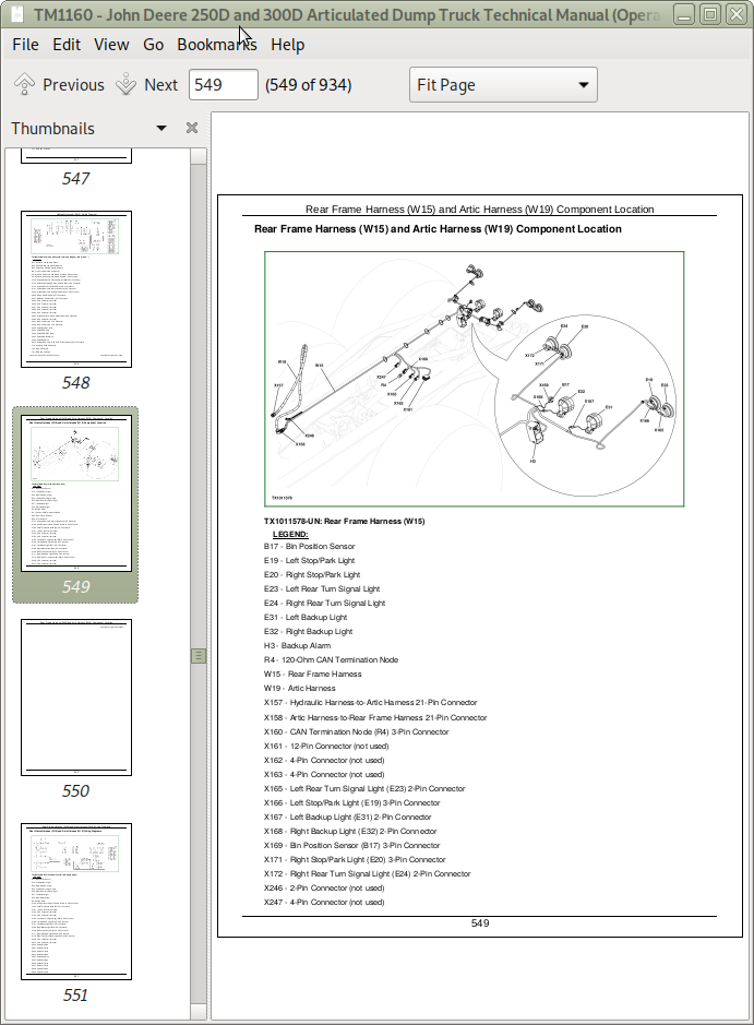
Rear Frame Harness (W15) and Artic Harness (W19) Component Location
Rear Frame Harness (W15) and Artic Harness (W19) Wiring Diagrams
Work Light Harness (W16) Component Location
Work Light Harness (W16) Wiring Diagram
Air Conditioner Actuator Harness (W18) Component Location
Air Conditioning Actuator Harness (W18) Wiring Diagram
AM/FM Radio Harness (W20) Component Location
AM/FM Radio Harness (W20) Wiring Diagram
JDLink™ System Harnesses Component Location—MIG/GTT
JDLink™ System Harnesses Component Location—MTG/SAT
JDLink™ System Wiring Diagram—MIG/GTT
JDLink™ Power Harness (W26) Wiring Diagram (S.N. 617193— )
JDLink™ System Wiring Diagrams—MTG/SAT
Seat Heater Harness (W33) Component Location—If Equipped
Seat Heater Harness (W33) Wiring Diagram—If Equipped
Group 15: Sub-System Diagnostics
Starting and Charging Circuit Theory of Operation
Engine Control Unit and Electronic Fuel Injection Control Circuit Theory of Operation
Transmission Control Unit and Retarder Circuit Theory of Operation
Chassis Control Unit Circuit Theory of Operation
Output Expansion Unit Circuit Theory of Operation
Bin Control and Range Hold Circuit Theory of Operation
Park Brake Circuit Theory of Operation
Monitor Display Unit Circuit Theory of Operation
Turn Lights and 4-Way Flasher Circuit Theory of Operation
Service Brake Light Circuit Theory of Operation
Backup Alarm and Backup Light Circuit Theory of Operation
Wiper/Washer Circuit Theory of Operation
Battery Balancer and 12-Volt Accessory Circuit Theory of Operation (S.N. 609166—617192)
Voltage Converter Theory of Operation (S.N. 617193— )
Air Conditioning Circuit Theory of Operation
Electric Mirror Circuit Theory of Operation
Unloader Valve Heater Circuit Theory of Operation
Group 20: References
Electrical Component Specifications
Sealed Switch Module (SSM) Test
Monitor Display Unit (MDU)—Service Mode
Diagnostic Trouble Codes—After Machine Repair
Diagnostic Trouble Codes—How Codes Are Displayed On Monitor Display Unit
Diagnostic Trouble Codes Quick Reference List
Service ADVISOR Diagnostic Application
Service ADVISOR™ Connection Procedure
Reading Diagnostic Trouble Codes with Service ADVISOR Diagnostic Application
Intermittent Diagnostic Trouble Code (DTC) Diagnostics
JDLink™ System Identification
JDLink™ Connection Procedure—If Equipped
Key Switch Test
Relay Test
Diode Test
CAN Circuit Testing
Pneumatic System Solenoids, Pressure Switches, and Sensor Tests
Hydraulic Pressure Switches Test
Hydraulic Temperature Sensors Test
Bin Position Sensor Test
Bin Sensor Calibration
Steering Column Switch Test
Transmission Solenoids, Speed Sensors, Sump Temperature Sensor, and Retarder Resistor Tests
Retarder Proportional Solenoid Test
Retarder Temperature Sensor Test
Transmission Shift Control Test
Engine Control Unit Remove and Install
Chassis Control Unit Remove and Install
Output Expansion Unit Remove and Install
Transmission Control Unit Remove and Install
Battery Balancer Remove and Install
Program Monitor Display Unit (MDU)
Monitor Display Unit Remove and Install
Replace DEUTSCH DEUTSCH is a trademark of Deutsch Co. Rectangular or Triangular Connectors
Replace DEUTSCH DEUTSCH is a trademark of the Deutsch Co. Connectors
Install DEUTSCH DEUTSCH is a trademark of the Deutsch Co. Contact
Replace WEATHER PACK WEATHER PACK is a trademark of Packard Electric. Connector
Install WEATHER PACK WEATHER PACK is a trademark of Packard Electric. Contact
Replace (Pull Type) Metri-Pack™ Connectors
Connector Terminal Test
Replace (Push Type) Metri-Pack™ Connectors
Remove Connector Body from Blade Terminals
Section 9020: Power Train
Group 05: Theory of Operation
Transmission External Components
Transmission Control System
Transmission Cross Sectional Diagram
Torque Converter Operation
Transmission Clutch Engagement
Transmission Retarder Operation
Transfer Case and Inter-Axle Differential Lock (IDL) Operation
Group 15: Diagnostic Information
Diagnostic Procedure
Diagnose Power Train System Malfunctions
Power Train Component Location Diagram
Group 25: Tests
Transmission Warm-Up Procedure
Transmission Pressure Test
Torque Converter Stall Test
Torque Converter Stator Tests
Transmission Oil-to-Air Cooler Restriction Test
Front Suspension Strut Leakage Check
Front Axle Suspension Strut Height Check
Park Brake Test
Park Brake Pad Thickness Check
Park Brake Adjustment
Wheel Hub Bearing Preload Adjustment (Wheel Installed)
Section 9022: Pneumatic System
Group 05: Theory of Operation
Pneumatic System Operation
Pneumatic System Operation With Pneumatic Control Valve—If Equipped
Air Pressure Supply Circuit Operation
Air Dryer and Unloader Valve
Pneumatic Manifold Component Location
Pneumatic System Schematic
Pneumatic System Schematic With Pneumatic Control Valve—If Equipped
Group 15: Diagnostic Information
Diagnostic Procedure
Diagnose Pneumatic System Malfunctions
Pneumatic System Component Location Diagram
Pneumatic System Component Location With Pneumatic Control Valve—If Equipped
Group 25: Tests
Pneumatic System Main Pressure Test and Adjustment
Park Brake Pressure Test
Section 9025: Hydraulic System
Group 05: Theory of Operation
Articulated Dump Truck Hydraulic System Operation
Main Hydraulic Pump Operation
Main Hydraulic Pump Load Sense Operation
Service Brake System Operation
Steering and Secondary Steering System Operation
Steering Valve Operation
Secondary Steering Pump Operation
Hydraulic System Manifold Operation
Bin Control Valve Operation
Hydraulic System Circuit Symbols
Hydraulic System Schematic
Group 15: Diagnostic Information
Diagnostic Procedure
Diagnose Hydraulic System Malfunctions
Diagnose Service Brake System Malfunctions
Diagnose Steering System Malfunctions
Hydraulic System Component Location
Group 25: Tests
JT02156A Digital Pressure/Temperature Analyzer Installation
Hydraulic Oil Cleanup Procedure
Hydraulic System Warm-Up Procedure
Cycle Time Test
Main Hydraulic Pump Residual and Compensator Valves Test and Adjustment
System Relief Valve and Bin Raise Circuit Relief Valve Test
Priority Valve Test
Accumulator Pressure Reducing Valve Test and Adjustment
Brake Accumulator Charge Valve Test and Adjustment
Brake Low Pressure Switch Test
Front and Rear Brake Apply Accumulators Pressure Test and Charge Procedure
Service Brake Valve Test
Steering Relief Valve Pressure Test and Adjustment
Steering Cylinder Leakage Test
Secondary Steering Pump Residual and Compensator Valves Test and Adjustment
Bin Lower Circuit Relief Valve Test
Section 9031: Heating and Air Conditioning
Group 05: Theory of Operation
Air Conditioning System Cycle of Operation
Heater Core Operation
Group 15: Diagnostic Information
Diagnose Air Conditioning System Malfunctions
Diagnose Heater System Malfunctions
Heating/Air Conditioning Component Location
Group 25: Tests
Air Conditioning Operational Checks
R134a Air Conditioning System Test
Operating Pressure Diagnostic Chart
A/C Freeze Control Switch Test
A/C Compressor Clutch Test
A/C High/Low Pressure Switch Test
A/C Expansion Valve Test
Expansion Valve Bench Test
Blower Motor Resistor/Thermofuse Test
Refrigerant Leak Test
![]()