
John Deere 650DLC Excavators Operation and Test Service Manual (TM10008)
John Deere 650DLC Excavators Operation and Test Service Manual (TM10008)
TM10008 - John Deere 650DLC Excavators Technical Manual - Operation and Test.PDF
Complete Diagnostic, Operation and Test manual with Electrical Wiring Diagrams for John Deere 650DLC Excavators, with all the shop information to maintain, diagnostic, repair, refurbish/rebuild like professional mechanics.
John Deere 650DLC Excavators workshop Operation and Test manual includes:
* Numbered table of contents easy to use so that you can find the information you need fast.
* Detailed sub-steps expand on repair procedure information
* Numbered instructions guide you through every repair procedure step by step.
* Troubleshooting and electrical service procedures are combined with detailed wiring diagrams for ease of use.
* Notes, cautions and warnings throughout each chapter pinpoint critical information.
* Bold figure number help you quickly match illustrations with instructions.
* Detailed illustrations, drawings and photos guide you through every procedure.
* Enlarged inset helps you identify and examine parts in detail.
Total Pages: 1,372 pages
File Format: PDF (bookmarked, ToC, Searchable, Printable, high quality)
Language: English
MAIN SECTIONS
Foreword
Technical Information Feedback Form
General Information
Safety
Diagnostics
Main Controller (MCF) Diagnostic Trouble Codes
Engine Control Module (ECM) Diagnostic Trouble Codes
Information Controller (ICF) Diagnostic Trouble Codes
Air Conditioner Controller (ACF) Diagnostic Trouble Codes
Monitor Controller (MON) Diagnostic Trouble Codes
Operational Checkout Procedure
Operational Checkout Procedure
Engine
Theory of Operation
Diagnostic Information
Tests
Electrical System
System Information
System Diagrams
Sub-System Diagnostics
Monitor Operation
References
Power Train
Theory of Operation
Diagnostic Information
Hydraulic System
Theory of Operation
Diagnostic Information
Tests
Heating and Air Conditioning System
Theory Of Operation
Diagnostic Information
Tests
Reference Material
Terminology Cross Reference Chart
tm10008 - 650DLC Excavator
Table of Contents
Foreword
Technical Information Feedback Form
Section 9000: General Information
Group 01: Safety
Recognize Safety Information
Follow Safety Instructions
Operate Only If Qualified
Wear Protective Equipment
Avoid Unauthorized Machine Modifications
Add Cab Guarding for Special Uses
Inspect Machine
Stay Clear of Moving Parts
Avoid High-Pressure Oils
Beware of Exhaust Fumes
Prevent Fires
Prevent Battery Explosions
Handle Chemical Products Safely
Dispose of Waste Properly
Prepare for Emergencies
Use Steps and Handholds Correctly
Start Only From Operator's Seat
Use and Maintain Seat Belt
Prevent Unintended Machine Movement
Avoid Work Site Hazards
Keep Riders Off Machine
Avoid Backover Accidents
Avoid Machine Tip Over
Use Special Care When Lifting Objects
Add and Operate Attachments Safely
Prevent Unintended Detonation of Explosive Devices
Park and Prepare for Service Safely
Service Cooling System Safely
Remove Paint Before Welding or Heating
Make Welding Repairs Safely
Drive Metal Pins Safely
Section 9001: Diagnostics
Group 10: Main Controller (MCF) Diagnostic Trouble Codes
Main Controller (MCF) Diagnostic Trouble Codes
11000.02 - Abnormal EEPROM
11001.02 - Abnormal RAM
11002.02 - Abnormal A/D Conversion
11003.03 - Abnormal Sensor Voltage
11004.02 - CAN Communication Error
11101.03 - Engine Speed Dial sensor Circuit Voltage High Input
11101.04 - Engine Speed Dial Sensor Circuit Voltage Low Input
11200.03 - Pump 1 Delivery Pressure Sensor Circuit Voltage High
11200.04 - Pump 1 Delivery Pressure Sensor Voltage Low
11202.03 - Pump 2 Delivery Pressure Sensor Circuit Voltage High
11202.04 - Pump 2 Delivery Pressure Sensor Voltage Low
11301.03 - Swing Pilot Pressure Sensor Circuit Voltage High
11301.04 - Swing Pilot Pressure Sensor Circuit Voltage Low
11302.03 - Boom Raise Pilot Pressure Sensor Circuit Voltage High
11302.04 - Boom Raise Pilot Pressure Sensor Circuit Voltage Low
11303.03 - Arm Roll-in Pilot Pressure Sensor Circuit Voltage High
11303.04 - Arm Roll-in Pilot Pressure Sensor Circuit Voltage Low
11400.03 - Pump 2 (5-Spool) Control Solenoid Valve Feedback Current High
11400.04 - Pump 2 (5-Spool) Control Solenoid Valve Feedback Current Low
11402.03 - Boom Flow Rate Solenoid (SF) Valve Feedback Current High
11402.04 - Boom Flow Rate Solenoid (SF) Valve Feedback Current Low
11404.03 - Power Dig Solenoid (SG) Valve Feedback Current High
11404.04 - Power Dig Solenoid (SG) Valve Feedback Current Low
11405.03 - Travel Speed Solenoid (SI) Valve Current Feedback High
11405.04 - Travel Speed Solenoid (SI) Valve Current Feedback Low
11410.03 - Pump 1 (4-Spool) Control Solenoid Valve Feedback Current High
11410.04 - Pump 1 (4-Spool) Control Solenoid Valve Feedback Current Low
11412.03 - Hydraulic Fan Pump Control Solenoid Valve Feedback Current High
11412.04 - Hydraulic Fan Pump Solenoid Valve Feedback Current Low
11802.03 - Boom Pressure Sensor Circuit Voltage High
11802.04 - Boom Pressure Sensor Circuit Voltage Low
11901.03 - Hydraulic Oil Temperature Sensor Circuit Voltage High
11901.04 - Hydraulic Oil Temperature Sensor Circuit Voltage Low
11910.02 - Actual Engine Speed Message Error
11911.02 - Security Signal Message Error
11914.02 - Radiator Coolant Temperature Message Error
11918.02 - Work Mode Message Error
11920.02 - Fuel Flow Rate Message Error
11976.03 - Auxiliary Valve 2 Feedback Current High
11976.04 - Auxiliary Valve 2 Feedback Current Low
11977.03 - Auxiliary Valve 1 Feedback Current High
11977.04 - Auxiliary Valve 1 Feedback Current Low
11980.03 - ATT Relief Change Valve Feedback Current High
11980.04 - ATT Relief Change Valve Feedback Current Low
11981.03 - Fan Reversing Solenoid Valve 2 Feedback Current High
11981.04 - Fan Reversing Solenoid Valve 2 Feedback Current Low
11982.03 - Fan Reversing Solenoid Valve 1 Feedback Current High
11982.04 - Fan Reversing Solenoid Valve 1 Feedback Current Low
11983.02 - Intake Air Temperature Message Error
11984.02 - Boost Temperature Message Error
11989.03 - Boom Mode Solenoid (SC) Valve Feedback Current High
11989.04 - Boom Mode Solenoid (SC) Valve Feedback Current Low
11991.03 - Travel Right Pilot Pressure Sensor Circuit Voltage High
11991.04 - Travel Right Pilot Pressure Sensor Circuit Voltage Low
11992.03 - Pump 2 (5-Spool) Control Pressure Sensor Circuit Voltage High
11992.04 - Pump 2 (5-Spool) Control Pressure Sensor Circuit Voltage Low
11993.03 - Travel Left Pilot Pressure Sensor Circuit Voltage High
11993.04 - Left Travel Pilot Pressure Sensor Circuit Low Input
11994.03 - Pump 1 (4-Spool) Control Pressure Sensor Circuit Voltage High
11994.04 - Pump 1 (4-Spool) Control Pressure Sensor Circuit Voltage Low
11995.03 - Arm Roll-Out Pilot Pressure Sensor Circuit Voltage High
11995.04 - Arm Roll-Out Pilot Pressure Sensor Circuit Low Input
11997.03 - Bucket Dump Pilot Pressure Sensor Circuit Voltage High
11997.04 - Bucket Dump Pilot Pressure Sensor Circuit Voltage Low
11998.03 - Boom Down Pilot Pressure Sensor Circuit Voltage High
11998.04 - Boom Down Pilot Pressure Sensor Circuit Voltage Low
11999.03 - Bucket Curl Pilot Pressure Sensor Circuit Voltage High
11999.04 - Bucket Curl Pilot Pressure Sensor Circuit Voltage Low
Group 20: Engine Control Module (ECM) Diagnostic Trouble Codes
Engine Control Module (ECM) Diagnostic Trouble Codes
91.02 - Accelerator Sensor 1-2 Comparison (P1271)
100.03 - Engine Oil Pressure Sensor Voltage Low (P0522)
100.04 - Engine Oil Pressure Sensor Voltage High (P0523)
102.03 - Boost Pressure Sensor Voltage Low (P0237)
102.04 - Boost Pressure Sensor Voltage High (P0238)
105.03 - Boost Temperature Sensor Voltage High (P1113)
105.04 - Boost Temperature Sensor Voltage Low (P1112)
108.03 - Barometric Pressure Sensor Voltage Low (P0107)
108.04 - Barometric Pressure Sensor Voltage High (P0108)
110.03 - Engine Coolant Temperature Sensor Voltage High (P0118)
110.04 - Engine Coolant Temperature Sensor Voltage Low (P0117)
157.00 - Common Rail Pressure—First Stage (P088)
157.00 - Common Rail Pressure—Second Stage (P088)
157.02 - Common Rail Pressure High (P0089)
157.03 - Common Rail Pressure Sensor Voltage High (P0193)
157.04 - Common Rail Pressure Sensor Voltage Low (P0192)
172.03 - Intake Air Temperature Sensor Voltage High (P0113)
172.04 - Intake Air Temperature Sensor Voltage Low (P0112)
174.03 - Fuel Temperature Sensor Voltage High (P0183)
174.04 - Fuel Temperature Sensor Voltage Low (P0182)
190.00 - Engine Overspeed (P0219)
628.02 - ROM Malfunction (P0601)
633.07 - Pressure Limiter Open (P1095)
636.02 - Camshaft Position Sensor (G-Sensor) Signal Missing (P0340)
636.02 - Camshaft Position Sensor (G-Sensor) Signal Mismatch (P0341)
636.07 - Camshaft Position Sensor (G-Sensor) out of Phase (P1345)
639.02 - CAN Communication Error (U2104)
639.03 - CAN Timeout (U2106)
651.03 - Open Circuit in Injection Nozzle #1 (P0201)
652.03 - Open Circuit in Injection Nozzle #2 (P0202)
653.03 - Open Circuit in Injection Nozzle #3 (P0203)
654.03 - Open Circuit in Injection Nozzle #4 (P0204)
655.03 - Open Circuit in Injection Nozzle #5 (P0205)
656.03 - Open Circuit in Injection Nozzle #6 (P0206)
723.02 - Crankshaft Position Sensor Signal Missing (P0335)
723.02 - Crankshaft Sensor Mismatch (P0336)
987.03 - Check Engine Lamp Malfunction (P0650)
1077.02 - CPU Fault Malfunction (P0606)
1079.02 - 5 Volt Power Supply #1 Malfunction (P1631)
1080.02 - 5 Volt Power Supply #2 Malfunction (P1632)
1239.01 - No Pump Pressure—First Stage (P1094)
1240.01 - No Pump Pressure Feed—Second Stage (P1093)
1347.00 - PCV #1 Open Circuit or Short to Ground (P0092)
1347.04 - PCV #1 Short to Power (P0091)
1348.00 - PCV # 2 Open Circuit or Short to Ground (P1291)
1348.04 - PCV #2 Short to Power (P1292)
1381.03 - Fuel Filter Pressure Sensor Voltage High (P1294)
1381.04 - Fuel Filter Pressure Sensor Voltage Low (P1293)
1485.02 - Engine Control Module Relay Malfunction (P1625)
10001.03 - EGR Position Sensor Malfunction (P0487)
10002.02 - EGR Valve Control Malfunction (P0488)
10003.02 - Injection Nozzle Common #1 Malfunction (P1261)
10004.02 - Injection Nozzle Common #2 Malfunction (P1262)
10005.01 - Charge Circuit Malfunction—Bank 1 (P0611)
10006.01 - Charge Circuit Malfunction—Bank 2 (P0612)
10007.02 - CPU Monitoring IC Malfunction (P0606)
10008.02 - A/D Conversion Malfunction (P1630)
10009.02 - 5 Volt Power Supply #3 Malfunction (P1633)
10010.02 - 5 Volt Power Supply #4 Malfunction (P1634)
10011.02 - 5 Volt Power Supply #5 Malfunction (P1635)
10013.02 - EEPROM Malfunction (P0603)
20100.02 - Engine Coolant Temperature High
20101.02 - Engine Warning
20110.02 - Fuel Filter Restricted (Level 1)
20110.02 - Fuel Filter Restricted (Level 2)
Group 30: Information Controller (ICF) Diagnostic Trouble Codes
Information Controller (ICF) Diagnostic Trouble Codes
14000.02 - Abnormal CAN Communication
14001.02 - ICF: Flash Memory: Read/Write Error
14002.02 - ICF: External RAM: Read/Write Error
14003.02 - ICF: EEPROM: Sum Check Error
14006.02 - ICF: Satellite Communication Terminal: Communication Error
14008.02 - ICF: Abnormal Internal RAM
14100.02 - Satellite Communication Terminal: Abnormal EEPROM
14101.02 - Satellite Communication Terminal: Abnormal IB/OB Queue
14102.02 - Satellite Communication Terminal: Abnormal Local Loop Back
14103.02 - Satellite Communication Terminal: The satellite is not found.
14104.02 - Satellite Communication Terminal: Fail 1 of Remote Loop Back
14105.02 - Satellite Communication Terminal: Fail 2 of Remote Loop Back
14106.02 - Satellite Communication Terminal: Sending and receiving data are mismatched
Group 40: Air Conditioner Controller (ACF) Diagnostic Trouble Codes
Air Conditioner Controller (ACF) Diagnostic Trouble Codes
E11 - Cab Air Temperature Sensor Open Circuit
E12 - Cab Air Temperature Sensor Short Circuit
E13 - Ambient Air Temperature Sensor Open Circuit
E14 - Ambient Air Temperature Sensor Short Circuit
E15 - Coolant Temperature Sensor Open Circuit
E16 - Coolant Temperature Sensor Short Circuit
E18 - Solar Sensor Abnormal
E21 - Freeze Control Switch Open Circuit
E22 - Freeze Control Switch Short Circuit
E43 - Abnormal Damper
E44 - Abnormal Damper
E45 - Abnormal Damper
E51 - Abnormal High/Low Pressure Switch
Group 50: Monitor Controller (MON) Diagnostic Trouble Codes
Monitor Controller (MON) Diagnostic Trouble Codes
13303.02 - Abnormal Thermister Temperature
13304.02 - Abnormal REG Input H Level
13306.02 - Abnormal EEPROM
13308.02 - Abnormal CAN Communication
13310.02 - Shorted circuit in Coolant Temperature Sensor
13311.03 - Shorted circuit in Fuel Level Sensor
13311.04 - Open circuit in Fuel Level Sensor
Section 9005: Operational Checkout Procedure
Group 10: Operational Checkout Procedure
Operational Checkout
Section 9010: Engine
Group 05: Theory of Operation
Engine Component Location
Engine Fuel System Operation
Engine Cooling System Operation
Engine Lubrication System Operation
Engine Intake and Exhaust System Operation
Engine Turbocharger Operation
Exhaust Gas Recirculation (EGR) Operation
Quick On Start (QOS) System Operation
Engine Speed Control System Operation
Group 15: Diagnostic Information
Isuzu AH-6WG1XYSA-02
Diagnose Engine Malfunctions
Engine Cranks But Will Not Start
Engine Misfires Or Runs Irregularly
Engine Does Not Develop Full Power
Engine Overheats
Auto-Idle Does Not Work
Coolant Temperature Too Low
Coolant in Oil or Oil in Coolant
Low Engine Oil Pressure
High Engine Oil Pressure
Engine Uses Too Much Oil
Engine Uses Too Much Fuel
Engine Emits Excessive White Exhaust Smoke
Engine Emits Excessive Black or Gray Exhaust Smoke
Turbocharger Excessively Noisy or Vibrates
Oil Dripping From Turbocharger Adapter
Excessive Drag in Turbocharger Rotating Members
Fuel In Oil
Group 25: Tests
Serpentine Belt Tension Check
Check and Adjust Injection Pump Timing
Engine Valve Lash (Clearance) Check and Adjust
Engine Compression Pressure Test
Air Filter Restriction Indicator Switch Test
Air Intake System Leakage Test
Engine Power Test Using Turbocharger Boost Pressure
Engine Oil Pressure Test
Section 9015: Electrical System
Group 05: System Information
Electrical Diagram Information
Group 10: System Diagrams
Explanation of Wire Markings
Fuse and Relay Specifications
System Functional Schematic, Wiring Diagram, and Component Location Master Legend
System Functional Schematic
Cab Harness (W1) Component Location
Cab Harness (W1) Wiring Diagram
Machine Harness (W2) Component Location
Machine Harness (W2) Wiring Diagram
Monitor Harness (W3) Component Location
Monitor Harness (W3) Wiring Diagram
Engine Harness (W4) Component Location
Engine Harness (W4) Wiring Diagram
Engine Interface Harness (W5) Component Location
Engine Interface Harness (W5) Wiring Diagram
Air Conditioner Harness (W6) Component Location
Air Conditioner Harness (W6) Wiring Diagram
Control Valve Harness (W7) Component Location
Control Valve Harness (W7) Wiring Diagram
Pump Harness (W8) Component Location
Pump Harness (W8) Wiring Diagram
Auxiliary Fuse Box Harness (W9) Component Location
Auxiliary Fuse Box Harness (W9) Wiring Diagram
Cab Switch Harness (W10) Component Location
Cab Switch Harness (W10) Wiring Diagram
Pilot Shutoff Switch Harness (W11) Component Location
Pilot Shutoff Switch Harness (W11) Wiring Diagram
Heated Air Seat Harness (W12) Component Location
Heated Air Seat Harness (W12) Wiring Diagram
Seat Heater Switch Harness (W13) Component Location
Seat Heater Switch Harness (W13) Wiring Diagram
Multi-Function Pilot Control Lever Harness (W14) Component Location
Multi-Function Pilot Control Lever Harness (W14) Wiring Diagram
Travel Alarm Cancel Switch Harness (W15) Component Location
Travel Alarm Cancel Switch Harness (W15) Wiring Diagram
Reversing Fan Switch Harness (W16) Component Location
Reversing Fan Switch Harness (W16) Wiring Diagram
Pilot Shutoff Valve Harness (W17) Component Location
Pilot Shutoff Valve Harness (W17) Wiring Diagram
Radiator Harness (W19) Component Location
Radiator Harness (W19) Wiring Diagram
Service Advisor Connector Harness (W22) Component Location
Service Advisor Connector Harness (W22) Wiring Diagram
JDLink™ System Harnesses Component Location—MIG/GTT
JDLink™ System Harnesses Component Location—MTG/SAT
JDLink™ System Wiring Diagrams—MIG/GTT
JDLink™ System Wiring Diagrams—MTG/SAT
Group 15: Sub-System Diagnostics
Controller Area Network (CAN) Theory of Operation
Starting and Charging Circuit Theory of Operation
Quick On System (QOS) Preheat Circuit Theory of Operation
Monitor Circuit Theory of Operation
Engine Control Module (ECM) Circuit Theory of Operation
Main Controller (MCF) Circuit Theory of Operation
Information Controller (ICF) Theory of Operation
Travel Alarm Circuit Theory of Operation
Windshield Wiper and Washer Circuit Theory of Operation
Pilot Shutoff Circuit Theory of Operation
JDLink™ Circuit Theory of Operation—If Equipped
Group 16: Monitor Operation
Monitor Menu Operation
Monitor Service Menu Operation
Group 20: References
Monitor Data Items
Monitor Data Items Using the Monitor Display
Reading Diagnostic Trouble Codes With Monitor Display
JDLink™ System Identification
JDLink™ Connection Procedure
Service ADVISOR™ Diagnostic Application
Service ADVISOR™ Connection Procedure
Reading Diagnostic Trouble Codes With Service ADVISOR™ Diagnostic Application
MPDr Application
MPDr Connection Procedure
Service ADVISOR™ Interactive Tests
Information Controller (ICF) Recorded Data
Pump Learning Procedure
Fuse Test
Relay Test
Pressure Sensor Test
Solenoid Test
Proportional Solenoid Test
Alternator Test
Electrical Component Checks
Battery Remove and Install
Rear Cover Remove and Install
Main Controller (MCF) Remove and Install
Engine Control Module (ECM) Remove and Install
Information Controller (ICF) Remove and Install
Monitor Controller Remove and Install
Key Switch Remove and Install
Switch Panel Remove and Install
Travel Alarm Remove and Install
Left Console Switch Remove and Install
Disconnect Tab Retainer Connectors
Disconnecting Spring Wire Clip Connectors
Replace DEUTSCH DEUTSCH is a trademark of the Deutsch Co. Connectors
Replace DEUTSCH DEUTSCH is a trademark of Deutsch Co. Rectangular or Triangular Connectors
Install DEUTSCH DEUTSCH is a trademark of the Deutsch Co. Contact
Replace WEATHER PACK WEATHER PACK is a trademark of Packard Electric. Connector
Install WEATHER PACK WEATHER PACK is a trademark of Packard Electric. Contact
Replace (Pull Type) Metri-Pack™ Connectors
Replace (Push Type) Metri-Pack™ Connectors
Replace CINCH CINCH is a trademark of the Cinch Co. Connectors
Install CINCH CINCH is a trademark of the Cinch Co. Contact
Repair 32 and 48 Way CINCH CINCH is a trademark of the Cinch Co. Connectors
Remove Connector Body from Blade Terminals
Section 9020: Power Train
Group 05: Theory of Operation
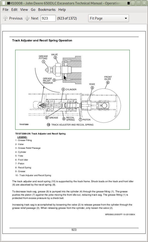
Track Adjuster and Recoil Spring Operation
Travel Gearbox Operation
Group 15: Diagnostic Information
Diagnose Undercarriage Components Malfunctions
Measure Swing Bearing Wear
Section 9025: Hydraulic System
Group 05: Theory of Operation
Hydraulic System Diagram and Operation
Fan Drive System Diagram and Operation
Pilot System Diagram and Operation
Pilot Pump, Pressure Regulating Valve, and Filter Operation
Pilot Check Valve Manifold and Accumulator Operation
Boom Lowering With Engine Stopped Circuit Operation
Pilot Shutoff Solenoid Valve Operation
Pilot Control Valve Operation
Travel Pilot Control Valve Operation
Boom Up Shockless Valve Operation
Pilot Signal Manifold Operation
Pilot Operation of Control Valve Operation
Pump 1 and 2, Fan Drive Pump, and Gearbox Operation
Pump 1 and 2 Regulator Operation
Fan Drive Pump Regulator Operation
Control Valve Operation
Control Valve Check Valves Identification and Operation
Main Relief and Power Digging Valve Circuit Operation
Circuit Relief and Anticavitation Valve Operation
Arm Make-Up Check Valve Operation
Travel Flow Combiner Valve Circuit Operation
Boom Regenerative Valve Circuit Operation
Arm Regenerative Valve Circuit Operation
Bucket Regenerative Valve Circuit Operation
Boom and Arm Reduced Leakage Valves Operation
Boom Flow Rate Circuit Operation
Arm 2 Flow Rate Circuit Operation
Boom Mode Circuit Operation
Counterweight Removal Circuit Operation
Swing Gearbox Operation
Swing Motor and Park Brake Circuit Operation
Swing Motor Park Brake Release Circuit Operation
Center Joint Operation
Travel Motor and Park Brake Circuit Operation
Travel Motor Speed Circuit Operation
Boom, Arm, and Bucket Cylinder Operation
Counterweight Removal Cylinder Operation
Return Filter Operation
Group 15: Diagnostic Information
Diagnose No Hydraulics Malfunctions
Diagnose All Hydraulics Slow Malfunctions
Diagnose All Hydraulic Functions Too Fast Malfunctions
Diagnose Hydraulic Overheating Malfunctions
Diagnose Fan Drive Hydraulic System Malfunctions
Diagnose Pilot Circuit Malfunctions
Diagnose Dig Circuit Malfunctions
Diagnose Swing Circuit Malfunctions
Diagnose Travel Circuit Malfunctions
Diagnose Counterweight Removal System Malfunctions
Diagnose Auto Lubrication System Malfunctions
Pump 1, Pump 2, Fan Drive Pump, and Pilot Pump Line Connections
Control Valve Line Identification
Swing Motor Line Identification
Control Lever Pattern Conversion
Pilot Control Valve-to-Pilot Signal Manifold Component Location—Excavator Pattern
Pilot Control Valve-to-Pilot Signal Manifold Component Location—Backhoe Pattern
Pilot Signal Manifold-to-Control Valve Line Connections
Travel Hydraulic System Component Location
Travel Hydraulic System Line Connection
Fan Drive System Component Location
Fan Drive System Line Connections
Hydraulic System Component Location
Hydraulic System Line Connections
Counterweight Removal Hydraulic System Component Location
Counterweight Removal Hydraulic System Line Connections
Hydraulic System Schematic
Group 25: Tests
Hydraulic Test Port Location
JT05800 Digital Thermometer Installation
JT02156A Digital Pressure/Temperature Analyzer Installation
Hydraulic Oil Cleanup Procedure Using Portable Filter Caddy
Hydraulic Oil Warm-Up Procedure
Pilot Pressure Regulating Valve Test and Adjustment
Control Valve Spool Actuating Pilot Pressure Test
Power Dig Solenoid Valve (port SG) Test and Adjustment
Travel Speed Solenoid Valve (port SI) Test and Adjustment
Boom Mode Solenoid Valve (port SC) Test and Adjustment
Boom Flow Rate Solenoid Valve (port SF) Test and Adjustment
Main Relief and Power Digging Valve Test and Adjustment
Circuit Relief Valve Test and Adjustment
Boom Mode Relief Valve Test and Adjustment
Pump Servo Piston Minimum Flow Test and Adjustment
Pump Servo Piston Maximum Flow Test and Adjustment
Pump Flow Rate (Displacement) Test and Adjustment
Swing Motor Crossover Relief Valve Test and Adjustment
Travel Motor Crossover Relief Valve Test and Adjustment
Swing Motor Leakage Test
Travel Motor Leakage Test
Cylinder Drift Test—Arm, Boom, and Bucket
Pump Flow Test
Fan Speed Tests
Fan Motor Case Drain Test
Fan Drive Pump Flow Test
Fan Drive System Relief Valve Test and Adjustment
Fan Drive Pump Servo Piston Minimum Flow Test and Adjustment
Fan Drive Pump Servo Piston Maximum Flow Test and Adjustment
Fan Drive Pump Flow Rate Test and Adjustment
Fan Drive Pump Torque Control Test and Adjustment
Section 9031: Heating and Air Conditioning System
Group 05: Theory Of Operation
Air Conditioning System Cycle of Operation
Group 15: Diagnostic Information
Diagnose Air Conditioning System Malfunctions
Diagnose Heating System Malfunctions
Air Conditioner and Heater Diagnostic Trouble Code Check
Heater and Air Conditioner Component Location
Group 25: Tests
Refrigerant Cautions and Proper Handling
Heating and Air Conditioning Operational Checks
R134a Air Conditioning System Test
Air Conditioner Compressor Clutch Test
Refrigerant Leak Test
Refrigerant Hoses and Tubing Inspection
Air Conditioner Compressor Belt Check and Adjustment
Operating Pressure Diagnostic Chart
Section 9050: Reference Material
Group 05: Terminology Cross Reference Chart
Terminology Cross Reference Chart
![]()