
John Deere 750 Excavator Service Repair Manual (TM1810)
Complete service repair manual for John Deere 750 Excavators, with workshop information to maintain, repair, and rebuild like professional mechanics.
John Deere 750 Excavators workshop service & repair manual includes:
* Numbered table of contents easy to use so that you can find the information you need fast.
* Detailed sub-steps expand on repair procedure information
* Numbered instructions guide you through every repair procedure step by step.
* Notes, cautions and warnings throughout each chapter pinpoint critical information.
* Bold figure number help you quickly match illustrations with instructions.
* Detailed illustrations, drawings and photos guide you through every procedure.
* Enlarged inset helps you identify and examine parts in detail.
TM1810 - John Deere 750 Excavator Technical Manual - Repair.PDF
TM1810 - John Deere 750 Excavator Technical Manual - Repair.EPUB
PRODUCT DETAILS:
Total Pages: 889 pages
File Format: PDF/EPUB/MOBI/AZW (PC/Mac/Android/Kindle/iPhone/iPad; bookmarked, ToC, Searchable, Printable)
Language: English
TABLE OF CONTENTS
Foreword
Technical Information Feedback Form
General Information
Safety
General Specifications
Torque Values
Fuels and Lubricants
Predelivery Assembly Instructions
Tracks
Track System
Axles and Suspension Systems (Propel)
Axle Shaft, Bearings and Reduction Gears
Hydraulic System
Engine
Removal and Installation
Engine Auxiliary System
Cold Weather Starting Aids
Cooling System
Speed Controls
Intake System
External Fuel Supply Systems
Connector Drive
Elements
Transfer or Splitter Drive
Removal and Installation
Gears, Shafts and Bearings
Electrical System
Batteries, Support and Cables
Alternator, Regulator and Charging System Wiring
Wiring Harness and Switches
System Controls
Instruments and Indicators
Frame or Supporting Structure
Frame Installation
Chassis Weights
Operator`s Station
Removal and Installation
Operator Enclosure
Seat and Seat Belt
Heating and Air Conditioning
Safety and Convenience
Horn and Warning Devices
Excavator
Buckets
Frames
Hydraulic System
Swing or Pivoting System
Mechanical Drive Elements
Hydraulic System
Dealer Fabricated Tools
Dealer Fabricated Tools
tm1810 - 750 Excavator
Table of Contents
Foreword
Technical Information Feedback Form
Section 00: General Information
Group 0001: Safety
Follow Safe Procedures
Prepare for Emergencies
Handle Fluids Safely-Avoid Fires
Prevent Battery Explosions
Handle Chemical Products Safely
Prevent Acid Burns
Avoid High-Pressure Fluids
Warn Others of Service Work
Park Machine Safely
Support Machine Properly
Operate Only from Operator's Seat
Stay Clear of Moving Parts
Avoid Power Lines
Use Handholds and Steps
Keep Riders Off Machine
Move and Operate Machine Safely
Wear Protective Clothing
Protect Against Flying Debris
Protect Against Noise
Illuminate Work Area Safely
Service Machines Safely
Remove Paint Before Welding or Heating
Avoid Heating Near Pressurized Fluid Lines
Beware of Exhaust Fumes
Use Proper Lifting Equipment
Service Cooling System Safely
Dispose of Waste Properly
Work in a Clean Area
Use Tools Properly
Replace Safety Signs
Live With Safety
Group 0002: General Specifications
750 Excavator Overview
750 Excavator
Working Ranges
Engine Specifications
Drain and Refill Capacities
Lift Capacity-KG (LB)
Group 0003: Torque Values
Hardware Torque Specifications
Unified Inch Bolt and Screw Torque Values
Metric Bolt and Screw Torque Values
Additional Metric Cap Screw Torque Values
Check Oil Lines And Fittings
Service Recommendations for O-Ring Boss Fittings
Service Recommendations For Flat Face O-Ring Seal Fittings
Service Recommendations for 37° Flare and 30° Cone Seat Connectors
Service Recommendations For Flared Connections-Straight or Tapered Threads
Service Recommendations For Inch Series Four Bolt Flange Fittings
Service Recommendations for Metric Series Four Bolt Flange Fitting
Group 0004: Fuels and Lubricants
Diesel Fuel
Lubricity of Diesel Fuels
Low Sulfur Diesel Fuel Conditioner
Diesel Fuel Storage
Fuel Tank
Do Not Use Galvanized Containers
Grease
Diesel Engine Oil
Hydraulic Oil
Swing Gearbox, Propel Gearbox and Pump Gearbox Oils
Track Roller, Front Idler, and Carrier Roller Oil
Track Adjuster, Working Tool Pivot, Swing Bearing, and Swing Bearing Gear Grease
Oil Filters
Lubricant Storage
Alternative and Synthetic Lubricants
Mixing of Lubricants
Group 0006: Predelivery Assembly Instructions
Specifications
Precautions for Assembling
Precautions for Lifting Work
Precautions for Operating Machine
Avoid High-Pressure Fluids
Installing Boom Cylinder
Installing Boom
Connecting Hoses Between Boom and Machine
Connecting Boom Cylinder Rod
Installing Arm
Connecting Arm Cylinder Rod
Connecting Bucket Cylinder Hoses
Installing Bucket
Adjusting Bucket Linkage
Attach Windshield Wiper
Retracting the Side Frame
Extending the Side Frame
Check Hydraulic Oil Level
Lubricate Working Tool Pivots
Installing Counterweight (Without Hydraulic Removal Option)
Counterweight Installation (With Hydraulic Removal Option)
Section 01: Tracks
Group 0130: Track System
Essential Tools
Service Equipment and Tools
Other Material
Specifications
Measure Lower Track Roller Wear
Remove and Install Lower Track Roller
Disassemble and Assemble Lower Track Roller
Inspect Metal Face Seals
Measure Track Carrier Roller Wear
Remove and Install Track Carrier Roller
Disassemble and Assemble Track Carrier Roller
Measure Track Shoe Grouser Wear
Remove and Install Track Shoe
Measure Track Chain Link Wear
Measure Track Chain Bushing Wear
Measure Track Chain Pitch
Remove Track Chain
Install Track Chain
Disassemble and Assemble Track Chain
Track Sag Adjustment
Remove and Install Sprocket
Measure Front Idler Wear
Remove and Install Front Idler
Disassemble Front Idler
Assemble Front Idler
Remove and Install Track Adjuster Cylinder and Recoil Spring
Disassemble and Assemble Track Adjuster Cylinder
Disassemble Track Adjuster Recoil Spring
Assemble Track Adjuster Recoil Spring
Section 02: Axles and Suspension Systems (Propel)
Group 0250: Axle Shaft, Bearings and Reduction Gears
Service Equipment and Tools
Other Material
Specifications
Remove and Install Propel Gearbox
Disassemble Propel Gearbox
Inspect Metal Face Seals
Assemble Propel Gearbox
Group 0260: Hydraulic System
Service Equipment and Tools
Other Material
Specifications
Remove and Install Propel Motor and Brake
Propel Motor Start-Up Procedure
Disassemble and Assemble Propel Motor and Brake
Remove and Install Propel Motor Crossover Relief Valves
Remove and Install Speed Selector Valve
Remove and Install Counterbalance Valve
Disassemble and Assemble Counterbalance Valve
Remove and Install Rotary Manifold
Disassemble and Assemble Rotary Manifold
Rotary Manifold Air Test
Remove and Install Propel Speed Change Solenoid Valve
Remove and Install Propel Flow Regulator
Disassemble and Assemble Propel Flow Regulator
Section 04: Engine
Group 0400: Removal and Installation
Essential Tools
Specifications
14L (875 cu. in.) N14 Series Cummins Engine
Remove and Install Engine
Inspect Crankcase Ventilation Tube
Measure and Adjust Injector and Engine Valve Clearances
Remove and Install Starting Motor
Section 05: Engine Auxiliary System
Group 0505: Cold Weather Starting Aids
Other Material
Remove and Install Starting Aid Solenoid and Nozzle
Group 0510: Cooling System
Service Equipment and Tools
Specifications
Remove and Install Fan, Shroud, and Guard
Remove and Install Fan Belt
Remove and Install Water Pump Belt
Remove and Install Alternator Belts
Inspect Belts and Check Tension
Remove and Install Radiator
Group 0515: Speed Controls
Service Equipment and Tools
Other Material
Specifications
Remove and Install Speed Control Linkage
Engine Speed Control Linkage Adjustment
Remove and Install Engine Controller (EC) Motor and Sensor
Engine Speed Programming Procedure After Battery Disconnection
Disassemble and Assemble Engine Controller (EC) Motor and Sensor
Group 0520: Intake System
Specifications
Remove and Install Air Cleaner
Air Intake Leakage Check
Group 0560: External Fuel Supply Systems
Specifications
Remove and Install Fuel Tank
Section 07: Connector Drive
Group 0752: Elements
Remove and Install Connector Drive Coupling
Section 08: Transfer or Splitter Drive
Group 0800: Removal and Installation
Specifications
Remove and Install Pump Drive Gearbox
Group 0851: Gears, Shafts and Bearings
Specifications
Disassemble and Assemble Pump Drive Gearbox
Section 16: Electrical System
Group 1671: Batteries, Support and Cables
Service Equipment and Tools
Specifications
Handle Batteries Safely
Engine Speed Programming Procedure After Battery Disconnection
Procedure for Testing Batteries
Check Battery Electrolyte Level and Terminals
Using Booster Batteries-24 Volt System
Charging Battery
Remove and Install Batteries
Adding 12 or 24 Volt Accessories
Group 1672: Alternator, Regulator and Charging System Wiring
Alternators and Starting Motors-Use CTM77
Service Equipment and Tools
Specifications
Remove and Install Alternator
Alternator Belt Tension Adjustment
Group 1674: Wiring Harness and Switches
Essential Tools
Engine and Frame Harness (W1) Component Location Diagram
Cab Harness (W2) Component Location Diagram
Monitor and Relay Harness (W3) Component Location Diagram
Connecting Engine Controller (EC) and Pump and Valve Controller (PVC) Harness Connector
Disconnect Tab Retainer Connectors
Disconnecting Spring Wire Clip Connectors
Replacing Fuses
Fuse (Blade-Type) Color Codes
Remove and Install Key Switch
Replace DEUTSCHDEUTSCH is a trademark of the Deutsch Co. Connectors
Install DEUTSCHDEUTSCH is a trademark of the Deutsch Co. Contact
Replace WEATHER PACK WEATHER PACK is a trademark of Packard Electric. Connector
Install WEATHER PACK WEATHER PACK is a trademark of Packard Electric. Contact
Remove Connector Body from Blade Terminals
Group 1675: System Controls
Welding On Machine
Remove and Install Engine Controller (EC) and Pump and Valve Controller (PVC)
Remove and Install Monitor Controller
Group 1676: Instruments and Indicators
Remove and Install Right Console Controller
Section 17: Frame or Supporting Structure
Group 1740: Frame Installation
Specifications
Welding On Machine
Welding Repair of Major Structure
Group 1749: Chassis Weights
Specifications
Remove and Install Counterweight (Without Hydraulic Removal Option)
Hydraulic Counterweight Removal Option Component Location
Remove Counterweight (With Hydraulic Removal Option)
Counterweight Installation (With Hydraulic Removal Option)
Section 18: Operator's Station
Group 1800: Removal and Installation
Specifications
Remove and Install Cab
Group 1810: Operator Enclosure
Service Equipment and Tools
Other Material
Remove and Install Windowpane and Two Piece Molding
Remove and Install Windowpane and One Piece Molding
Remove and Install Sliding Windows
Group 1821: Seat and Seat Belt
Specifications
Check Seat Adjustments
Remove and Install Seat
Remove and Install Seat Belt
Inspect Seat Belt
Group 1830: Heating and Air Conditioning
Essential Tools
Service Equipment and Tools
Other Material
Specifications
Proper Refrigerant Handling
R134a Refrigerant Cautions
R134a Compressor Oil Charge Check
R134a Compressor Oil Removal
R134a Component Oil Charge
R134a Refrigerant Recovery, Recycling, and Charging Station Installation Procedure
Recover R134a System
Evacuate R134a System
Charge R134a System
Check and Adjust Compressor Belt Tension
Heater and Air Conditioner Component Location
Remove and Install Air Conditioning Compressor
Disassemble and Assemble Air Conditioning Compressor
Remove and Install Receiver Dryer
Remove and Install Heater Core and Evaporator
Remove and Install Condenser
Remove and Install Heater Hoses
Air Conditioner Self-Diagnostic Procedure
Section 20: Safety and Convenience
Group 2004: Horn and Warning Devices
Remove and Install Travel Alarm
Changing Travel Alarm Volume
Section 33: Excavator
Group 3302: Buckets
Specifications
Replacing Bucket Teeth
Replacing Bucket Tooth Tip (Heavy Duty Bucket)
Welding On Machine
Remove and Install Tooth Shank
Replace Welded Bucket Cutting Edges
Repair Cracked Cutting Edge
Installing Bucket
Adjusting Bucket Linkage
Group 3340: Frames
Service Equipment and Tools
Other Material
Specifications
Remove and Install Arm
Remove and Install Boom
Inspect Arm and Boom Pins and Bushings
Remove and Install Bushings and Seals
Group 3360: Hydraulic System
Service Equipment and Tools
Other Material
Specifications
Control Lever Pattern Conversion
Electronic Control Bypass Procedure
Lower Boom With Engine Stopped
Hydraulic Oil Cleanup Procedure Using Portable Filter Caddy
Remove and Install Hydraulic Pump
Hydraulic Pump Start-Up Procedure
Disassemble Hydraulic Pump
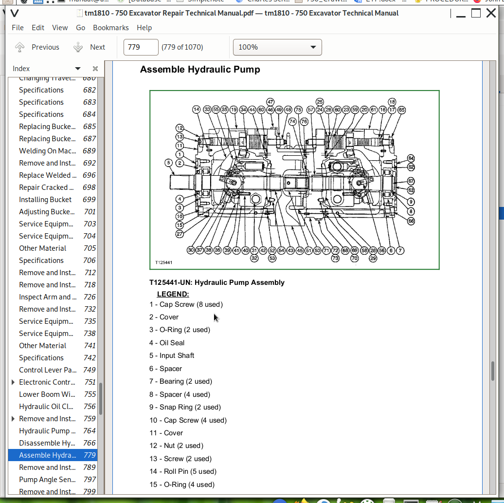
Assemble Hydraulic Pump
Remove and Install Hydraulic Pump Angle Sensor (A Sensor)
Pump Angle Sensor Adjustment
Remove and Install Hydraulic Pump Pressure Sensor
Remove and Install Hydraulic Pump Displacement Solenoid Valve
Remove and Install Hydraulic Pump Regulator
Disassemble and Assemble Hydraulic Pump Regulator
Remove and Install Pilot Pump
Disassemble and Assemble Pilot Pump
Remove and Install Pilot Filter
Hydraulic Oil Filter Inspection Procedure
Remove and Install Case Drain Filter
Remove and Install Solenoid Valve Manifold and Pilot Pressure Regulating Valve
Disassemble and Assemble Solenoid Valve Manifold and Pilot Pressure Regulating Valve
Remove and Install Pilot Shut-Off Valve
Disassemble And Assemble Pilot Shut-Off Valve
Pilot Shut-Off Valve Linkage Adjustment
Remove and Install Pilot Check Valve Block
Disassemble and Assemble Pilot Check Valve Block
Remove and Install Dig Flow Regulator Valve
Disassemble and Assemble Dig Flow Regulator Valve
Remove and Install Swing Priority Solenoid Valve
Disassemble and Assemble Swing Priority Solenoid Valve
Remove and Install Dig and Swing Function Pilot Shuttle Check Valve
Disassemble and Assemble Dig and Swing Function Pilot Shuttle Check Valve
Remove and Install Pilot Controller
Disassemble and Assemble Dig Function Pilot Controller
Remove and Install Propel Function Pilot Check Valve
Disassemble and Assemble Propel Function Pilot Check Valve
Remove and Install Propel Pilot Controller
Disassemble and Assemble Propel Pilot Controller
Remove and Install Counterweight Pilot Controller
Disassemble and Assemble Counterweight Pilot Controller
Remove and Install Main Control Valve
Disassemble and Assemble Main Control Valve
Disassemble and Assemble System Relief Valve
Disassemble and Assemble Circuit Relief and Anti-Cavitation Valve
Remove and Install Pressure Differential (DP) Sensor
Remove and Install Boom Cylinder
Remove and Install Arm Cylinder
Remove and Install Bucket Cylinder
Remove and Install Counterweight Lift Cylinder
Disassemble Boom, Arm, Bucket, or Counterweight Cylinder
Assemble Boom, Arm, Bucket or Counterweight Cylinder
Hydraulic Cylinder Bleeding Procedure
Remove and Install Hydraulic Oil Cooler
Remove and Install Hydraulic Oil Cooler Bypass Valve
Remove and Install Restriction Valve
Remove and Install Hydraulic Oil Tank
Section 43: Swing or Pivoting System
Group 4350: Mechanical Drive Elements
Service Equipment and Tools
Other Material
Specifications
Remove and Install Swing Gearbox
Swing Gearbox Start-Up Procedure
Disassemble Swing Gearbox
Assemble Swing Gearbox
Remove Upperstructure
Install Upperstructure
Remove and Install Swing Bearing
Disassemble And Assemble Swing Bearing
Install Swing Bearing Upper Seal
Install Swing Bearing Lower Seal
Group 4360: Hydraulic System
Service Equipment and Tools
Other Material
Specifications
Remove and Install Swing Motor and Brake
Swing Motor Start-Up Procedure
Disassemble Swing Motor and Brake
Assemble Swing Motor and Brake
Remove And Install Swing Brake Release Valve
Remove And Install Crossover Relief Valves And Make-Up Valves
Section 99: Dealer Fabricated Tools
Group 9900: Dealer Fabricated Tools
Rotary Manifold Lifting Tool
DFT1077 Spool Holding Fixture
DFT1177 Propel Gearbox Nut Wrench
John Deere 750 Excavator Service Repair Manual (TM1810)
![]()