
John Deere 690E LC Excavator Operation and Test Service Manual (TM1508)
Complete Diagnostics, Operation & Test Service manual with Electrical Wiring Diagrams for John Deere 690E LC Excavator, with all the workshop information to maintain, diagnose, and service like professional mechanics.
John Deere 690E LC Excavator workshop Diagnosis and Test manual includes:
* Numbered table of contents easy to use so that you can find the information you need fast.
* Detailed sub-steps expand on repair procedure information
* Numbered instructions guide you through every repair procedure step by step.
* Troubleshooting and electrical service procedures are combined with detailed wiring diagrams for ease of use.
* Notes, cautions and warnings throughout each chapter pinpoint critical information.
* Bold figure number help you quickly match illustrations with instructions.
* Detailed illustrations, drawings and photos guide you through every procedure.
* Enlarged inset helps you identify and examine parts in detail.
TM1508 - John Deere 690E LC Excavator Technical Manual - Operation and Test.pdf
TM1508 - John Deere 690E LC Excavator Technical Manual - Operation and Test.epub
Total Pages: 1,004 pages
File Format: PDF/EPUB/MOBI/AZW (PC/Mac/Android/Kindle/iPhone/iPad; bookmarked, ToC, Searchable, Printable)
Language: English
MAIN SECTIONS
Foreword
Technical Information Feedback Form
General Information
Safety
General Specifications
Torque Values
Fuels And Lubricants
Operational Checkout Procedure
Operational Checkout Procedure
Engine
Theory Of Operation
System Operational Checks
Diagnostic Information
Adjustments
Tests
Electrical System
System Information
System Diagrams
Sub-System Diagnostics
References
Power Train
Theory Of Operation
System Operational Checks
Diagnostic Information
Adjustments
Tests
Hydraulic System
Theory Of Operation
System Operational Checks
Diagnostic Information
Adjustments
Tests
Air Conditioning System
Theory Of Operation
CONTENTS - Expanded View
9000 - General Information
01 - Safety
Avoid Heating Near Pressurized Fluid Lines
Avoid High-Pressure Fluids
Avoid Power Lines
Beware of Exhaust Fumes
Dispose of Waste Properly
Follow Safe Procedures
Handle Chemical Products Safely
Handle Fluids Safely—Avoid Fires
Illuminate Work Area Safely
Keep Riders Off Machine
Live With Safety
Move and Operate Machine Safely
Operate Only from Operator's Seat
Park Machine Safely
Prepare for Emergencies
Prevent Acid Burns
Protect Against Flying Debris
Protect Against Noise
Remove Paint Before Welding or Heating
Replace Safety Signs
Service Cooling System Safely
Service Machines Safely
Stay Clear of Moving Parts
Support Machine Properly
Use Handholds and Steps
Use Proper Lifting Equipment
Use Tools Properly
Warn Others of Service Work
Wear Protective Clothing
Work in a Clean Area
02 - General Specifications
690E LC And 690E LC Long Front Drain And Refill Capacities
690E LC Long Front Specifications
690E LC
03 - Torque Values
Additional Metric Cap Screw Torque Values
Metric Bolt and Screw Torque Values
Service Recommendations for 37° Flare and 30° Cone Seat Connectors
Service Recommendations For Flared Connections—Straight or Tapered Threads
Service Recommendations For Flat Face O-Ring Seal Fittings
Service Recommendations For Inch Series Four Bolt Flange Fittings
Service Recommendations for Metric Series Four Bolt Flange Fitting
Service Recommendations for O-Ring Boss Fittings
Unified Inch Bolt and Screw Torque Values
04 - Fuels and Lubricants
Alternative and Synthetic Lubricants
Diesel Engine Oil
Diesel Fuel
Hydraulic Oil
Low Sulfur Diesel Fuel Conditioner
Lubricant Storage
Mixing of Lubricants
Oil Filters
Propel Gearbox Oil
Track Adjuster, Working Tool Pivot, Swing Bearing, And Swing Bearing Gear Grease
Track Roller, Front Idler, And Carrier Roller Oil
9001 - Diagnostic Trouble Codes (DTC)
100 - Tire Pressure Monitoring (TPM) System Diagnostic Trouble Codes
10 - Engine Control Unit (ECU) Diagnostic Trouble Codes
10 - Main Controller (MCF) Diagnostic Trouble Codes
20 - Engine Control Module (ECM) Diagnostic Trouble Codes
20 - Transmission Control Unit (TCU) Diagnostic Trouble Codes
30 - Flex Load Controller (FLU) Diagnostic Trouble Codes
30 - Information Controller (ICF) Diagnostic Trouble Codes
40 - Air Conditioner Controller (ACF) Diagnostic Trouble Codes
40 - Sealed Switch Module (SSM) Diagnostic Trouble Codes
50 - Advanced Display Unit (ADU) Diagnostic Trouble Codes
50 - Monitor Controller (MON) Diagnostic Trouble Codes
60 - Radar Object Detection (RDD) Diagnostic Trouble Codes
70 - Ground Speed Radar (RDR) Diagnostic Trouble Codes
80 - Joystick Steering Valve (JSV) Diagnostic Trouble Codes
90 - Joystick Steering Controller (JSC) Diagnostic Trouble Codes
9005 - Operational Checkout Procedure
10 - System Operational Checks
Operational Checkout
Operational Checkout Record Sheet—690E LC
9010 - Engine
05 - Theory of Operation
6068 John Deere Engine (Serial No. —559602)—Use CTM8
6068 John Deere Engine (Serial No. 559603—)—Use CTM104
Engine Power Mode And Work Mode Operation
Engine—Sectional View
Engine Speed Control System Operation
Fan Drive Operation (Serial No. —559602)
Fan Drive Operation (Serial No. 559603—)
General Engine Description
10 - System Operation Checks
6068 John Deere Engine (Serial No. —559602)—Use CTM8
6068 John Deere Engine (Serial No. 559603—)—Use CTM104
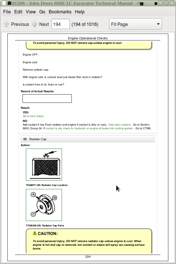
Engine Operational Checks
15 - Diagnostic Information
6068 John Deere Engine (Serial No. —559602)—Use CTM8
6068 John Deere Engine (Serial No. 559603—)—Use CTM104
Diagnose Engine Malfunctions
20 - Adjustments
6068 John Deere Engine (Serial No. —559602)—Use CTM8
6068 John Deere Engine (Serial No. 559603—)—Use CTM104
Engine Speed Check
Engine Speed Control Linkage Adjustment
Engine Speed Sensor Adjustment
JT05801 Clamp-On Electronic Tachometer Installation
25 - Tests
6068 John Deere Engine (Serial No. —559602)—Use CTM8
6068 John Deere Engine (Serial No. 559603—)—Use CTM104
Air Filter Restriction Indicator Switch Test
Air Intake System Leakage Test
Engine Power Test Using Turbocharger Boost Pressure
Fuel Line Leakage Test
Radiator Air Flow Test
9015 - Electrical System
05 - System Information
Electrical Circuit Malfunctions
Electrical Schematic Symbols
Grounded Circuit
High Resistance Circuit
Multimeter
Open Circuit
Reading A Wiring Diagram
Seven Step Electrical Test Procedure—Continued
Seven Step Electrical Test Procedure
Shorted Circuit
Visually Inspect Electrical System
Wiring Diagram And Schematic Information
10 - System Diagrams
Cab Harness Wiring Diagram
Component Identification Table
Component Location Diagram
Engine Harness Wiring Diagram
Fuse (Blade-Type) Color Codes
Fuse Specifications
System Functional Schematic
Vehicle Harness Wiring Diagram
Wiring And Schematic Diagram
15 - Sub-System Diagnostics
Alternator Operation—40 Amp Delco Remy
Alternator Operation—45 Amp Bosch
Auto Idle Circuit Operational Information
Auto Idle Circuit Schematic
Auto Idle Circuit Theory Of Operation
Charging Circuit Operational Information
Charging Circuit Schematic
Charging Circuit Theory Of Operation
Horn, Dome Light, Cigar Lighter And Heater Circuits Operational Information
Horn, Dome Light, Cigar Lighter And Heater Circuits Schematic
Horn, Dome Light, Cigar Lighter And Heater Circuits Theory Of Operation
Light Circuit Operational Information
Light Circuit Schematic
Light Circuit Theory Of Operation
Monitor, Monitor Controller And Switch Panel 1 Circuit Operational Information
Monitor, Monitor Controller And Switch Panel 1 Circuit Schematic
Monitor, Monitor Controller And Switch Panel 1 Circuit Specifications
Monitor, Monitor Controller And Switch Panel 1 Circuit Theory Of Operation
Power Circuit Operational Information
Power Circuit Schematic
Power Circuit Theory Of Operation
Start Aid And Propel Alarm Circuit Operational Information
Start Aid And Propel Alarm Circuit Schematic
Start Aid And Propel Alarm Circuit Theory Of Operation
Starter Operation
Starting Circuit Operational Information
Starting Circuit Schematic
Starting Circuit Theory Of Operation
Switch Panel 1 Circuit Operational Information
Switch Panel 1 Circuit Schematic
Switch Panel 1 Circuit Theory Of Operation
Switch Panel 2 Circuit Operational Information
Switch Panel 2 Circuit Schematic
Switch Panel 2 Circuit Theory Of Operation
System Controller Circuit Operational Information
System Controller Circuit Schematic
System Controller Circuit Specifications
System Controller Circuit Theory Of Operation
Windshield Wiper And Washer Circuit Operational Information
Windshield Wiper And Washer Circuit Schematic
Windshield Wiper And Washer Circuit Theory Of Operation
20 - References
Adding 12-Volt Accessories
Alternator Voltage Output Test—Bosch
Alternator Voltage Output Test—Delco
Battery Operation
Battery Specifications
Changing Travel Alarm Volume
Check Battery Electrolyte Level And Terminals
Connecting Systems Controller Harness Connector
Diagnose Battery Malfunctions
Disconnecting Tab Retainer Connectors
Engine Speed Sensor Adjustment
Harness Side Of Connectors With Pin Locations
Monitor Panel And Switch Panels
Monitor Panel
Procedure For Testing Batteries
Replacing Batteries
Switch Panel 2
Using Booster Batteries—24 Volt System
Welding On Machine
9020 - Power Train
05 - Theory of Operation
Carrier Roller Operation
Combined Function Shuttle Valve Operation—(Serial No. —556935)
Combined Function Shuttle Valve Operation—(Serial No. 556936—)
Counterbalance Valve Operation—Braking
Counterbalance Valve Operation—Neutral
Counterbalance Valve Operation—Propel
Front Idler Operation
Power Train Components—(Serial No. —556935)
Power Train Components—(Serial No. 556936—)
Propel Brake And Pressure Reducing Valve Operation
Propel Circuit Operation
Propel Control Valve Operation
Propel Crossover Relief Valve And Shuttle Valve Operation
Propel Gearbox Operation
Propel Motor Cover Operation
Propel Motor Operation
Propel Pilot Check Valve Block Operation—Forward
Propel Pilot Circuit Operation—(Serial No. —556935)
Propel Pilot Circuit Operation—(Serial No. 556936—)
Propel Pilot Controller Operation—Neutral
Propel Speed Change Solenoid Valve Operation
Propel Speed Change Valve Operation
Rotary Manifold Operation
Supply Shuttle Valve Operation
Swing Bearing Operation
Track Adjuster Operation
Track Roller Operation
10 - System Operational Checks
Power Train Operational Checks
15 - Diagnostic Information
Diagnose Malfunctions Of The Propel System
Measure Front Idler Wear
Measure Lower Track Roller Wear
Measure Track Chain Bushing Wear
Measure Track Chain Link Wear
Measure Track Chain Pitch
Measure Track Shoe Grouser Wear
Measure Upper Track Roller Wear
Propel Component Location
20 - Adjustments
Measure And Adjust Track Sag
Propel Control Valve Spool Stop Screw Adjustment
25 - Tests
Hydraulic System Warm-Up Procedure
JT02156A Digital Pressure And Temperature Analyzer Installation
JT05800 Digital Thermometer Installation
JT05801 Clamp-On Electronic Tachometer Installation
Propel Brake Release Pressure Reducing Valve Test And Adjustment
Propel Motor Case Drain Leakage Test
Propel Motor Crossover Relief Valve Test And Adjustment
Propel Motor Start-Up Procedure
Propel Speed Change Solenoid Valve Test
Propel Speed Cycle Time
9025 - Hydraulic System
05 - Theory of Operation
Anti-Drift Valves For Arm And Boom Operation
Arm Cylinder Restrictor Operation
Arm, Regenerative And Anti-Drift Valves Schematic
Arm Regenerative Valve Operation—(Serial No. 546277—556935)
Arm Regenerative Valve Operation—(Serial No. 556936—)
Boom, Arm And Bucket Control Valve Operation—Combined
Boom, Arm And Bucket Control Valve Operation—Full Actuation
Boom, Arm And Bucket Control Valve Operation—Neutral
Boom, Arm And Bucket Control Valve Operation—Starting To Move
Boom Cylinder Restrictor Operation—(Serial No. 556936—)
Boom, Regenerative And Anti-Drift Valves Schematic
Boom Regenerative Valve Operation—(Serial No. 545157—556935)
Boom, Swing, And Arm Control Valve Operation—(Serial No. 556936—)
Boom, Swing, And Arm Control Valve Schematic—(Serial No. 556936—)
Circuit Relief And Anticavitation Valve Operation
Control System Operation
Control Valve And Manifold Operation—(Serial No. —556935)
Control Valve And Manifold Schematic (Serial No. —556935)
Control Valve Manifold Operation—(Serial No. —556935)
Control Valve Manifold Operation (Serial No. 556936—)
Control Valve Manifold Operation—(Serial No. 556936—)
Control Valve Sections Operation
Cylinder Operation
Dig Pilot Check Valve Operation
Drain Circuit Operation
Dual Solenoid Block Operation
Engine Speed Control Actuator Operation—Fast Idle
Engine Speed Control Actuator Operation—Manual Override
Engine Speed Control Actuator Operation—Slow Idle
Hydraulic Reservoir
Hydraulic System Components—(Serial No. —556935)
Hydraulic System Components—(Serial No. 556936—)
Hydraulic System Operation—(Serial No. —556935)
Hydraulic System Operation—(Serial No. 556936—)
Load Sense System Relief Valve Operation
Main Pump Operation (Serial No. —559602)
Main Pump Operation (Serial No. 559603—)
Make-Up Valve Operation
Pilot Circuit Operation
Pilot Controller Operation—Full Stroke
Pilot Controller Operation—Metering
Pilot Controller Operation—Neutral
Pilot Filter Operation
Pilot Pressure Regulating Valve Operation—(Serial No. —556935)
Pilot Pressure Regulating Valve Operation—(Serial No. 556936—)
Pilot Pump Operation
Pilot Shut-Off Valve Operation
Power Boost Solenoid Operation—Actuated (Serial No. —556935)
Power Boost Solenoid Operation (Serial No. 556936—)
Pressure Control Manifold Operation (Serial No. —556935)
Pump Displacement Solenoid Operation—(Serial No. —559602)
Pump Displacement Solenoid Operation—(Serial No. 559603—)
Pump High Pressure Control Operation
Pump Low Pressure Control Operation
Pump Neutral Control Operation
Pump Regulator—Fixed And Maximum Displacement (Serial No. —559602)
Pump Regulator—Fixed And Maximum Displacement (Serial No. 559603—)
Pump Regulator—Minimum Displacement Operation (Serial No. —559602)
Pump Regulator—Minimum Displacement Operation (Serial No. 559603—)
Return Circuit Operation
Return Manifold Operation (Serial No. 556936—)
Safety Relief Valve Operation
Swing And Swing Torque Control Valves Schematic
Swing Brake Release Solenoid Operation
Swing Control Valve Operation
Swing Crossover Relief Valve Operation
Swing Crossover Relief Valve Operation—Relief
Swing Gearbox Operation
Swing Motor Operation
Swing Stop Cushion Valve Operation (Serial No. 546277—)
Swing Torque Control Valve OperationFor Long Front Machines—(Serial No. —546276)
Swing Torque Control Valve OperationFor Long Front Machines—(Serial No. 546277—)
Switch Panel 2 Operation
System Controller Operation
10 - System Opertional Checks
Hydraulic Operational Checks
15 - Diagnostic Informtion
Diagnose Hydraulic System Malfunctions
Hydraulic Circuit Symbols
Main Hydraulic Circuit Component Location (Serial No. —556935)
Main Hydraulic Circuit Component Location (Serial No. 556936—)
Main Hydraulic Schematic (Serial No. —556935)
Main Hydraulic Schematic (Serial No. 556936—)
Pilot Circuit Component Location (Serial No. —556935)
Pilot Circuit Component Location (Serial No. 556936—)
Pilot Controller Lines—John Deere Pattern
Pilot Controller Lines—Standard Pattern (SAE)
Pilot Control Lever Pattern Information
20 - Adjustments
Arm Cylinder Restrictor (Rod End) Adjustment
Boom Cylinder Restrictor (Head End) Adjustment (Serial No. 556936—)
Control Valve Spool Stop Screw Adjustment For Long Front Machine
Control Valve Spool Stop Screw Adjustment
Hydraulic System Warm-Up Procedure
JT05800 Digital Thermometer Installation
Lower Boom With Engine Stopped
Pilot Shut-Off Valve Linkage Adjustment
Raise Boom With Engine Stopped
Swing Upperstructure With Engine Stopped
25 - Tests
Auxiliary Function Circuit Relief Valve Test And Adjustment
Cycle Times For Long Front
Cycle Times
Cylinder Drift Test For Boom, Arm And Bucket
Dig Function Circuit Relief Valve Test And Adjustment (Serial No. —556935)
Dig Function Circuit Relief Valve Test And Adjustment (Serial No. 556936—)
Hydraulic Control Valve Return Anticavitation Check Valve Test
Hydraulic Oil Cleanup Procedure Using Clean-Up Filter
Hydraulic Oil Cleanup Procedure Using Portable Filter Caddy
Hydraulic Oil Filter Inspection Procedure
Hydraulic Pump Case Drain Flow Test
Hydraulic Pump Displacement Solenoid Valve Test And Adjustment
Hydraulic Pump Start-Up Procedure
Hydraulic Pump Test Using Cycle Time Method
Hydraulic Pump Test Using Flow Meter Method
Hydraulic System Warm-Up Procedure
JT02156A Digital Pressure And Temperature Analyzer Installation
JT05800 Digital Thermometer Installation
JT05801 Clamp-On Electronic Tachometer Installation
Load Sense Valve Differential Pressure Test And Adjustment
Manual Bypass Pressure Reducing Valve Test And Adjustment
Oil Cooler Pressure Drop Test
Pilot Pressure Regulating Valve Test And Adjustment
Pilot Pump Flow Test
Power Boost Solenoid Valve Test
Reservoir Pressure Test
Swing Brake And Gearbox Lubrication And Cooling Flow Test
Swing Brake And Gearbox Start-Up Procedure
Swing Motor Case Drain Flow Test
Swing Motor Crossover Relief Valve Test And Adjustment
Swing Motor Start-Up Procedure
Swing Torque Control Valve Test And Adjustment For Long Front Machines (Serial No. —546276)
Swing Torque Control Valve Test And Adjustment (Serial No. 546277—)
System Relief Valve Test And Adjustment
TM Worksheet 1 Of 7—690E LC Excavator
TM Worksheet 2 Of 7—690E LC Excavator
TM Worksheet 3 Of 7—690E LC Excavator
TM Worksheet 4 Of 7—690E LC Excavator
TM Worksheet 5 Of 7—690E LC Excavator
TM Worksheet 6 Of 7—690E LC Excavator Art (Serial No. —556935)
TM Worksheet 7 Of 7—690E LC Excavator Art (Serial No. 556936—)
9031 - Heating and Air Conditioning
05 - Theory of Operation
Air Conditioning Circuit Operation
Air Conditioning Fan Operation
Air Conditioning System Operation
Compressor Relief Valve Operation
Expansion Valve Operation
Heater Operation
Receiver _ Dryer Operation
10 - System
Air Conditioning Operational Checks
Air Conditioning System (Serial No. —541550)
15 - Diagnostic Informtion
Air Conditioning Component Location (Serial No. —541550)
Diagnose Air Conditioning Electrical Malfunctions (Serial No. —541550)
20 - Adjustments
Add Refrigerant To The System
Air Conditioning Gauge Set Installation Procedure
Air Conditioning System (Serial No. —541550)
Charge The System
Check And Add Compressor Oil
Check And Adjust Compressor Belt Tension
Evacuate The System
Refrigerant (R-12) Cautions
Refrigerant Recovery
25 - Tests
Air Conditioning System (Serial No. —541550)
Air Conditioning System Test
Expansion Valve Bench Test And Adjustment
Expansion Valve Operating Test
High Refrigerant Pressure Switch Test
Leak Testing
Low Refrigerant Pressure Switch Test
Operating Pressure Diagnostic Chart
Refrigerant Hoses And Tubing Inspection
Refrigerant (R-12) Cautions
John Deere 690E LC Excavator Operation and Test Service Manual (TM1508)
![]()