
John Deere 690E LC Excavator Service Repair Manual (TM1509)
Complete service repair manual for John Deere 690E LC Excavator, with all the technical information to maintain, repair, and rebuild like professional mechanics.
John Deere 690E LC Excavator workshop service & repair manual includes:
* Numbered table of contents easy to use so that you can find the information you need fast.
* Detailed sub-steps expand on repair procedure information
* Numbered instructions guide you through every repair procedure step by step.
* Bold figure number help you quickly match illustrations with instructions.
* Detailed illustrations, drawings and photos guide you through every procedure.
* Enlarged inset helps you identify and examine parts in detail.
TM1509 - John Deere 690E LC Excavator Technical Manual - Repair.pdf
TM1509 - John Deere 690E LC Excavator Technical Manual - Repair.epub
Total Pages: 824 pages
File Format: PDF/EPUB/MOBI/AZW (PC/Mac/Android/Kindle/iPhone/iPad; bookmarked, ToC, Searchable, Printable)
Language: English
TABLE OF CONTENTS
Foreword
General Information
Safety
General Specifications
Torque Values
Fuels And Lubricants
Tracks
Track System
Axles And Suspension Systems
Axle Shaft, Bearings, And Reduction Gears
Hydraulic System
Engine
Removal And Installation
Engine Auxiliary System
Cold Weather Starting Aids
Cooling System
Speed Controls
Intake System
External Exhaust Systems
External Fuel Supply Systems
Dampener Drive (Flex Coupling)
Elements
Electrical System
Batteries, Support, And Cables
Alternator, Regulator, And Charging Wiring
Lighting System
Wiring Harness And Switches
System Controls
Instruments And Indicators
Frame Or Supporting Structure
Frame Installation
Chassis Weights
Operator’s Station
Removal And Installation
Operator Enclosure
Seat
Heating And Air Conditioning
Safety And Convenience
Horn And Warning Devices
Excavator
Bucket
Frames
Hydraulic System
Swing Or Pivoting System
Brakes
Mechanical Drive Elements
Hydraulic System
Dealer Fabricated Tools
Total Pages: 1,233 pages
File Format: PDF (bookmarked, ToC, Searchable, Printable, high quality)
Language: English
CONTENTS - Expanded View
00 - General Information
01 - Safety
Avoid Heating Near Pressurized Fluid Lines
Avoid High-Pressure Fluids
Avoid Power Lines
Beware of Exhaust Fumes
Dispose of Waste Properly
Follow Safe Procedures
Handle Chemical Products Safely
Handle Fluids Safely-Avoid Fires
Illuminate Work Area Safely
Keep Riders Off Machine
Live With Safety
Move and Operate Machine Safely
Operate Only from Operator's Seat
Park Machine Safely
Prepare for Emergencies
Prevent Acid Burns
Protect Against Flying Debris
Protect Against Noise
Remove Paint Before Welding or Heating
Replace Safety Signs
Service Cooling System Safely
Service Machines Safely
Stay Clear of Moving Parts
Support Machine Properly
Use Handholds and Steps
Use Proper Lifting Equipment
Use Tools Properly
Warn Others of Service Work
Wear Protective Clothing
Work in a Clean Area
02 - General Specifications
690E LC And 690E LC Long Front Drain And Refill Capacities
690E LC Long Front Specifications
690E LC
03 - Torque Values
Additional Metric Cap Screw Torque Values
Metric Bolt and Cap Screw Torque Values
Service Recommendations for 37° Flare and 30° Cone Seat Connectors
Service Recommendations For Flared Connections-Straight or Tapered Threads
Service Recommendations for Flat Face O-Ring Seal Fittings
Service Recommendations For Inch Series Four Bolt Flange Fittings
Service Recommendations for Metric Series Four Bolt Flange Fitting
Service Recommendations for O-Ring Boss Fittings
Unified Inch Bolt and Cap Screw Torque Values
04 - Fuels & Lubricants
Alternative and Synthetic Lubricants
Diesel Engine Oil
Diesel Fuel
Do Not Use Galvanized Containers
Fuel Tank
Hydraulic Oil
Low Sulfur Diesel Fuel Conditioner
Lubricant Storage
Mixing of Lubricants
Oil Filters
Propel Gearbox Oil
Storing Fuel
Track Adjuster, Working Tool Pivot, Swing Bearing, And Swing Bearing Gear Grease
Track Roller, Front Idler, And Carrier Roller Oil
01 - Wheels or Tracks
Assemble Front Idler
Disassemble And Assemble Lower Track Roller
Disassemble And Assemble Recoil Spring
Disassemble And Assemble Track Adjuster Cylinder
Disassemble And Assemble Track Chain
Disassemble And Assemble Track Chain To Replace Broken Part
Disassemble And Assemble Upper Track Roller
Disassemble Front Idler
Inspect Metal Face Seals
Install Track Chain
Measure And Adjust Track Sag
Measure Front Idler Wear
Measure Lower Track Roller Wear
Measure Track Chain Bushing Wear
Measure Track Chain Link Wear
Measure Track Chain Pitch
Measure Track Shoe Grouser Wear
Measure Upper Track Roller Wear
Other Material
Remove And Install Front Idler
Remove And Install Lower Track Roller
Remove And Install Sprocket
Remove And Install Track Adjuster Cylinder And Recoil Spring
Remove And Install Track Guide
Remove And Install Track Shoes
Remove And Install Upper Track Roller
Remove Track Chain
Service Equipment And Tools
Specifications
Test Front Idler For Oil Leakage
Test Lower Track Roller For Oil Leakage
02 - Axles and Suspension Systems
50 - Axle Shaft, Bearings, and Reduction Gears
Assemble Propel Gearbox
Assemble Replacement Housing And Bearing Assembly
Disassemble Propel Gearbox
Inspect Metal Face Seals
Other Material
Remove And Install Propel Gearbox And Brake
Replace Propel Gearbox Brake Elements
Service Equipment And Tools
Special Or Essential Tools
Specifications
Towing Machine
60 - Hydraulic System
Assemble Propel Motor
Disassemble And Assemble Counterbalance Valve
Disassemble And Assemble Propel Speed Change Solenoid Valve
Disassemble And Assemble Rotary Manifold
Disassemble Propel Motor
Disassemble Valve Housing And Cover
Other Material
Propel Motor Start-Up Procedure
Remove And Install Brake Release Pressure Reducing Valve
Remove And Install Counterbalance Valve
Remove And Install Crossover Relief Valve
Remove And Install Low Speed Selector Valve
Remove And Install Propel Hydraulic Lines
Remove And Install Propel Motor
Remove And Install Propel Speed Change Solenoid Valve
Remove And Install Rotary Manifold
Remove And Install Shuttle Valve
Remove And Install Supply Shuttle Valve
Rotary Manifold Air Test
Service Equipment And Tools
Specifications
04 - Engine
6068 John Deere Engine-Use CTM104
6068 John Deere Engine-Use CTM8
Bleed Fuel System (Serial No. -559602)
Bleed Fuel System (Serial No. 559603-)
Change Final Fuel Filter (Serial No. 559603-)
Change Fuel Filter (Serial No. -559602)
Change Primary Fuel Filter _ Water Separator (Serial No. 559603-)
Check And Adjust Engine Valve Lash (Clearance) (Serial No. -559602)
Check And Adjust Engine Valve Lash (Clearance) (Serial No. 559603-)
Clean Injection Nozzle Bores
Installing DB4 Fuel Injection Pump (Serial No. -559602)
JT07158 TIME TRAC ® Installation
Other Material
Remove And Install DB4 Fuel Injection Pump (Serial No. 559603-)
Remove And Install Engine (Serial No. -559602)
Remove And Install Engine (Serial No. 559603-)
Remove And Install Exhaust Manifold (Serial No. -559602)
Remove And Install Exhaust Manifold (Serial No. 559603-)
Remove And Install Fuel Injection Nozzles
Remove And Install Fuel Transfer Pump (Serial No. -559602)
Remove And Install Fuel Transfer Pump (Serial No. 559603-)
Remove And Install Intake Manifold Tube (Serial No. -559602)
Remove And Install Intake Manifold Tube (Serial No. 559603-)
Remove And Install Oil Cooler (Serial No. -559602)
Remove And Install Oil Cooler (Serial No. 559603-)
Remove And Install Oil Pan
Remove And Install Starter (Serial No. -559602)
Remove And Install Starter (Serial No. 559603-)
Remove And Install Thermostat (Serial No. -559602)
Remove And Install Thermostat (Serial No. 559603-)
Remove And Install Turbocharger (Serial No. -559602)
Remove And Install Turbocharger (Serial No. 559603-)
Remove And Install Water Pump (Serial No. -559602)
Remove And Install Water Pump (Serial No. 559603-)
Removing DB4 Fuel Injection Pump (Serial No. -559602)
Service Equipment And Tools
Special Or Essential Tools
Specifications
05 - Engine Auxiliary Systems
05 - Cold Weather Starting Aids
Other Material
Remove And Install Engine Coolant Heater
Remove And Install Starting Aid Solenoid And Nozzle
Specifications
10 - Cooling System
Inspect Serpentine Belt (Serial No. 559603-)
Inspect Serpentine Belt (Serial No.
Remove And Install Fan, Guards, And Shroud (Serial No. -559602)
Remove And Install Fan, Guards, And Shroud (Serial No. 559603-)
Remove And Install Radiator
Specifications
15 - Speed Controls
Adjust Engine Speed Control Linkage
Remove And Install Speed Control Linkage
Specifications
20 - Intake System
Air Intake System Leakage Test
Remove And Install Air Cleaner
Service Equipment And Tools
Special Or Essential Tools
Specifications
30 - External Exhaust System
Remove And Install Muffler
60 - External Fuel Supply Systems
Disassemble And Assemble Primary Fuel Filter (Water Separator) (Serial No. 559603-)
Other Material
Remove And Install Fuel Tank
Remove And Install Primary Fuel Filter (Water Separator) (Serial No. 559603-)
Remove And Install Water Separator (Serial No. -559602)
Replace Water Separator Filter Element (Serial No. -559602)
Specifications
07 - Dampener Drive (Flex Coupling)
Remove And Install Dampener Drive (Flex Coupler) (Serial No. -559602)
Remove And Install Dampener Drive (Flex Coupler) (Serial No. 559603-)
Specifications
16 - Electrical System
71 - Batteries, Support, and Cables
Adding 12-Volt Battery Accessories
Charge Battery
Check Battery Electrolyte Level And Terminals
Checking Electrolyte Specific Gravity
Handle Batteries Safely
Procedure For Testing Batteries
Remove And Install Batteries
Service Equipment And Tools
Specifications
Using Booster Batteries-24-Volt System
72 - Alternator, Regulator, and Charging System Wiring
Alternators And Starting Motors-Use CTM77
Remove And Install Alternator (Serial No. -541822)
Remove And Install Alternator (Serial No. 541823-559602)
Remove And Install Alternator (Serial No. 559603-)
Specifications
73 - Lighting System
Fuse (Blade-Type) Color Codes
Fuse Specifications
Replacing Fuses
Replacing Halogen Bulbs
Work Light Adjustment
74 - Wiring Harness and Switches
Cab Electrical Component Identification
Engine Electrical Component Identification
Install DEUTSCH ™ Contact
Install WEATHER PACK ™ Contact
Remove And Install Monitor Buzzer And Air Conditioner Switch
Remove And Install Radio, Propel Alarm Cancel Switch, And Start Aid Switch
Remove And Install Starter Switch
Remove Connector Body From Blade Terminals
Replace DEUTSCH ™ Connectors
Replace WEATHER PACK ™ Connector
Special Or Essential Tools
Vehicle Electrical Component Identification
75 - System Controls
Remove And Install Monitor Controller
Remove And Install System Controller
Welding On Machine
76 - Instruments and Indicators
Remove And Install Hour Meter, Coolant Temperature And Fuel Level Gauges
Remove And Install Monitor Panel
Remove And Install Switch Panel 1
Remove And Install Switch Panel 2
Replace Monitor Panel Bulbs
Replace Switch Panel 2 Bulb
17 - Frames, Chassis, or Supporting Structure
40 - Frame Installation
Specifications
Welding Repair Of Major Structure
49 - Chassis Weight
Other Material
Remove And Install Counterweight
Service Equipment And Tools
Specifications
18 - Operator's Station
00 - Removal & Installation
Remove And Install Cab
Specifications
10 - Operator Enclosure
Other Material
Remove And Install Sliding Windows
Remove And Install Windowpane And One Piece Molding
Remove And Install Windowpane And Two Piece Molding
Service Equipment And Tools
Windowpane Dimensions
21 - Seat & Seat Belt
Disassemble And Assemble Seat (Serial No. 537781-538404)
Disassemble And Assemble Seat (Serial No. 538405-549976)
Disassemble And Assemble Seat (Serial No. 549977-)
Disassemble And Assemble Seat Stand (Serial No. -547853)
Disassemble And Assemble Seat Stand (Serial No. 547854-)
Remove And Install Seat (Serial No. -538404)
Remove And Install Seat (Serial No. 538405-)
30 - Heating & Air Conditioning System
Add Refrigerant To The System (Serial No. -541550)
Air Conditioning Gauge Set Installation Procedure
Assemble Compressor (Serial No. -541550)
Charge The System (Serial No. -541550)
Check And Add Compressor Oil (Serial No. -541550)
Clutch Pulley, Bearing And Hub Inspection
Disassemble And Inspect Compressor (Serial No. -541550)
Evacuate The System (Serial No. -541550)
Expansion Valve Bench Test And Adjustment (Serial No. -541550)
Inspect Vee Belt, Check And Adjust Tension-Air Conditioned Machines Only (Serial No. -541550)
Leak Testing (Serial No. -541550)
Make Shaft Seal Leak Test (Serial No. -541550)
Other Material
Refrigerant Hoses And Tubing Inspection (Serial No. -541550)
Refrigerant (R-12) Cautions (Serial No. -541550)
Refrigerant Recovery (Serial No. -541550)
Remove And Install Air Conditioning Switch (Serial No. -541550)
Remove And Install Blower Motor
Remove And Install Compressor (Serial No. -541550)
Remove And Install Condenser (Serial No. -541550)
Remove And Install Evaporator (Serial No. -541550)
Remove And Install Expansion Valve (Serial No. -541550)
Remove And Install Heater Control
Remove And Install Heater Core And Blower Motor Relay
Remove And Install Low And High Pressure Switches (Serial No. -541550)
Remove And Install Receiver _ Dryer (Serial No. -541550)
Remove And Install Thermostat Switch, Air Conditioner Relay, And Compressor Relay
Replace Shaft Seal Seat
Replacing Clutch Pulley Bearing
Service Equipment And Tools
Special Or Essential Tools
Specifications
Volumetric Efficiency Test-R12 (Serial No. -541550)
20 - Safety & Convenience
Changing Travel Alarm Volume
Remove And Install Propel Alarm
33 - Excavator
02 - Buckets
Adjust Bucket Linkage
Remove And Install Bucket And Linkage (Serial No. -538759)
Remove And Install Bucket And Linkage (Serial No. 538760-)
Remove And Install Tooth Shank
Repair Cracked Cutting Edge
Replace Welded Bucket Cutting Edges
Replacing Bucket Tooth Tip-Heavy-Duty Bucket
Specifications
40 - Frames
Other Material
Remove And Install Arm
Remove And Install Boom
Remove And Install Bushings And Seals
Specifications
60 - Hydraulic System
Assemble Bucket, Arm And Boom Cylinders
Assemble Hydraulic Pump (Serial No. -559602)
Change Hydraulic Return Filter
Disassemble And Assemble Arm Regenerative Valve (Serial No. 546277-556935)
Disassemble And Assemble Arm Regenerative Valve (Serial No. 556936-)
Disassemble And Assemble Auxiliary Valve Section (Serial No. -556935)
Disassemble And Assemble Boom And Arm Anti-Drift Valve
Disassemble And Assemble Boom, Arm, And Bucket Valve Section (Serial No. -556935)
Disassemble And Assemble Boom, Arm, And Swing Control Valve (Serial No. 556936-)
Disassemble And Assemble Boom Regenerative Valve (Serial No. 545157-556935)
Disassemble And Assemble Combined Function Shuttle Valve (Serial No. 556936-)
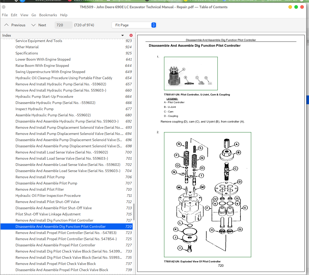
Disassemble And Assemble Dig Function Pilot Controller
Disassemble And Assemble Dual Solenoid Valve Block (Serial No. 538539-)
Disassemble And Assemble Engine Speed Control Actuator
Disassemble And Assemble Hydraulic Pump (Serial No. 559603-)
Disassemble And Assemble Load Sense System Relief Valve (Serial No. -556935)
Disassemble And Assemble Load Sense System Relief Valve (Serial No. 556936-)
Disassemble And Assemble Load Sense Valve (Serial No. -559602)
Disassemble And Assemble Load Sense Valve (Serial No. 559603-)
Disassemble And Assemble Monoblock Control Valve Manifold (Serial No. 556936-)
Disassemble And Assemble Pilot Pressure Regulating Valve (Serial No. -556935)
Disassemble And Assemble Pilot Pressure Regulating Valve (Serial No. 556936-)
Disassemble And Assemble Pilot Pump
Disassemble And Assemble Pilot Shut-Off Valve
Disassemble And Assemble Propel Pilot Check Valve Block
Disassemble And Assemble Propel Pilot Controller
Disassemble And Assemble Propel Valve Section (Serial No. -556935)
Disassemble And Assemble Pump Displacement Solenoid Valve (Serial No. -559602)
Disassemble And Assemble Pump Displacement Solenoid Valve (Serial No. 559603-)
Disassemble And Assemble Reservoir
Disassemble And Assemble Safety Relief Valve (Serial No. 556936-)
Disassemble And Assemble Safety Valve (Serial No. -556935)
Disassemble And Assemble Swing Stop Cushion Valve (Serial No. 546277-)
Disassemble And Assemble Swing Torque Control Valve (Serial No. -546276)
Disassemble And Assemble Swing Torque Control Valve (Serial No. 546277-)
Disassemble And Assemble Swing Valve Section
Disassemble Bucket, Arm, And Boom Cylinders
Disassemble Hydraulic Pump (Serial No. -559602)
Hydraulic Cylinder Bleed Procedure
Hydraulic Oil Cleanup Procedure Using Portable Filter Caddy
Hydraulic Oil Filter Inspection Procedure
Hydraulic Pump Start-Up Procedure
Inspect Hydraulic Pump
Lower Boom With Engine Stopped
Other Material
Pilot Shut-Off Valve Linkage Adjustment
Raise Boom With Engine Stopped
Remove And Install Anti-Cavitation Back Pressure Check Valve (Serial No. -556935)
Remove And Install Anti-Cavitation Back Pressure Check Valve (Serial No. 556936-)
Remove And Install Arm And Boom Cylinder Restrictors (Serial No. 556936-)
Remove And Install Arm Cylinder
Remove And Install Arm Cylinder Restrictor (Serial No. 546276-556935)
Remove And Install Arm Regenerative Poppet Valve (Serial No. 556936-)
Remove And Install Arm Regenerative Valve (Serial No. 546277-556935)
Remove And Install Boom And Arm Anti-Drift Valve (Serial No. -556935)
Remove And Install Boom And Arm Anti-Drift Valve (Serial No. 556936-)
Remove And Install Boom, Arm, And Swing Control Valve Manifold (Serial No. 556936-)
Remove And Install Boom Cylinder
Remove And Install Boom Regenerative Valve (Serial No. 545157-556935)
Remove And Install Bucket Circuit Relief And Anti-Cavitation Valves (Serial No. 556936-)
Remove And Install Bucket Cylinder
Remove And Install Circuit Relief And Anti-Cavitation Valves (Serial No. -556935)
Remove And Install Combined Function Shuttle Valve (Serial No. -556935)
Remove And Install Combined Function Shuttle Valve (Serial No. 556936-)
Remove And Install Dig Function Pilot Controller
Remove And Install Dig Pilot Check Valve Block (Serial No. 543990-559935)
Remove And Install Dig Pilot Check Valve Block (Serial No. 559936-)
Remove And Install Dual Solenoid Block (Serial No. -538538)
Remove And Install Dual Solenoid Block (Serial No. 538539-)
Remove And Install Engine Speed Control Actuator
Remove And Install Hydraulic Control Valve (Serial No. -556935)
Remove And Install Hydraulic Oil Cooler
Remove And Install Hydraulic Pump (Serial No. -559602)
Remove And Install Hydraulic Pump (Serial No. 559603-)
Remove And Install Load Sense System Relief Valve (Serial No. 556936-)
Remove And Install Load Sense Valve (Serial No. -559602)
Remove And Install Load Sense Valve (Serial No. 559603-)
Remove And Install Make-Up Valve (Serial No. -556935)
Remove And Install Monoblock Control Valve (Serial No. 556936-)
Remove And Install Oil Cooler Bypass Valve (Serial No. 556936-)
Remove And Install Pilot Filter
Remove And Install Pilot Pressure Regulating Valve (Serial No. 556936-)
Remove And Install Pilot Pump
Remove And Install Pilot Shut-Off Valve
Remove And Install Power Boost Solenoid Valve (Serial No. -556935)
Remove And Install Power Boost Solenoid Valve (Serial No. 556936-)
Remove And Install Pressure Control Manifold (Serial No. -556935)
Remove And Install Propel Circuit Make-Up Valve (Serial No. 556936-)
Remove And Install Propel Pilot Check Valve Block
Remove And Install Propel Pilot Controller (Serial No. -547853)
Remove And Install Propel Pilot Controller (Serial No. 547854-)
Remove And Install Pump Displacement Solenoid Valve (Serial No. -559602)
Remove And Install Pump Displacement Solenoid Valve (Serial No. 559603-)
Remove And Install Reservoir
Remove And Install Return Manifold (Serial No. 556936-)
Remove And Install Safety Relief Valve (Serial No. 556936-)
Remove And Install Swing Stop Cushion Valve
Remove And Install Swing Torque Control Valve (Serial No. -556935)
Remove And Install Swing Torque Control Valve (Serial No. 556936-)
Service Equipment And Tools
Special Or Essential Tools
Specifications
Swing Upperstructure With Engine Stopped
43 - Swing or Pivoting System
11 - Brakes
Disassemble And Assemble Swing Brake
Remove And Install Swing Brake
Service Equipment Tools
Specifications
50 - Mechanical Drive Elements
Disassemble And Assemble Swing Gearbox
Install Swing Bearing Lower Seal
Install Swing Bearing Upper Seal
Install Upperstructure
Other Material
Remove And Install Swing Bearing
Remove And Install Swing Gearbox
Remove Upperstructure
Service Equipment And Tools
Specifications
Swing Brake And Gearbox Start-Up Procedure
60 - Hydraulic System
Disassemble And Assemble Swing Motor
Other Material
Remove And Install Crossover Relief Valve
Remove And Install Swing Motor Seal
Remove And Install Swing Motor (Serial No. -556935)
Remove And Install Swing Motor (Serial No. 556936-)
Service Equipment And Tools
Specifications
Swing Motor Start-Up Procedure
99 - Dealer Fabricated Tools
DF1039 Pump Workbench Support
DF1040 Pump Rotate Group Workbench Support
DF1052 Disk Holder Tool
DF1054 Swing Gearbox Nut Spanner Wrench
DFT1074 Swing Gearbox Pinion Holder Fixture
DFT1077 Spool Holding Fixture
DFT1087 Track Recoil Spring Disassembly And Assembly Guard Tool
DFT1089 Barrel Support
DFT1094 Bearing Pilot Tool
DFT1095 Planetary Gear Assembly Tool
DFT1096 Planetary Gear Shaft Removal Tool
DFT1108 Spool Holding Fixture
DFT1110 Spacer
DFT1111 Spacer
JT38009 Guide Pin
Rotary Manifold Lifting Tool
ST4920 Track Recoil Spring Disassembly And Assembly Tool
John Deere 690E LC Excavator Service Repair Manual (TM1509)
![]()