
John Deere Excavators 490D, 590D Service Repair Manual (TM1390)
Complete service repair manual for John Deere Excavators 490D, 590D, with service information to maintain, repair, and rebuild like professional mechanics.
John Deere Excavators 490D, 590D workshop service repair manual includes:
* Numbered table of contents easy to use so that you can find the information you need fast.
* Detailed sub-steps expand on repair procedure information
* Numbered instructions guide you through every repair procedure step by step.
* Notes, cautions and warnings throughout each chapter pinpoint critical information.
* Bold figure number help you quickly match illustrations with instructions.
* Detailed illustrations, drawings and photos guide you through every procedure.
* Enlarged inset helps you identify and examine parts in detail.
TM1390 - John Deere 490D and 590D Excavator Technical Manual - Repair.PDF
TM1390 - John Deere 490D and 590D Excavator Technical Manual - Repair.EPUB
Total Pages: 723 pages
File Format: PDF/EPUB/MOBI/AZW (PC/Mac/Android/Kindle/iPhone/iPad; bookmarked, ToC, Searchable, Printable)
Language: English
MAIN SECTIONS
Foreword
General Information
Safety
General Specifications
Torque Values
Fuels And Lubricants
Tracks
Track System
Axles And Suspension Systems (Propel)
Axle Shaft, Bearings, And Reduction Gears
Hydraulic System
Engine
Removal And Installation
Engine Auxiliary Systems
Cold Weather Starting Aids
Cooling System
Speed Controls
Intake System
External Fuel Supply Systems
Dampener Drive (Flex Coupling)
Elements
Electrical System
Batteries, Support, And Cables
Alternator, Regulator And Charging System Wiring
Wiring Harness And Switches
Motors And Actuators
Frame Or Supporting Structure
Frame Installation
Chassis Weights
Operator’s Station
Removal And Installation
Operator Enclosure
Seat And Seat Belt
Heating And Air Conditioning
Sheet Metal And Styling
Hood Or Engine Enclosure
Excavator
Buckets
Frames
Hydraulic Systems
Swing Or Pivoting System
Mechanical Drive Elements
Hydraulic System
Dealer Fabricated Tools
tm1390 - 490D and 590D Excavator
Table of Contents
Foreword
Section I: General Information
Group I: Safety
Follow Safe Procedures
Prepare for Emergencies
Prevent Acid Burns
Handle Chemical Products Safely
Handle Fluids Safely-Avoid Fires
Avoid High-Pressure Fluids
Warn Others of Service Work
Support Machine Properly
Operate Only from Operator's Seat
Park Machine Safely
Stay Clear of Moving Parts
Avoid Power Lines
Use Handholds and Steps
Keep Riders Off Machine
Move and Operate Machine Safely
Wear Protective Clothing
Protect Against Flying Debris
Protect Against Noise
Illuminate Work Area Safely
Service Machines Safely
Remove Paint Before Welding or Heating
Avoid Heating Near Pressurized Fluid Lines
Beware of Exhaust Fumes
Use Proper Lifting Equipment
Service Cooling System Safely
Dispose of Waste Properly
Work in a Clean Area
Use Tools Properly
Replace Safety Signs
Live With Safety
Group II: General Specifications
490D Specifications
490D Working Ranges
490D Drain And Refill Capacities
490D
490D Bucket Selection Chart-2.5 M (98 In.) Arm
490D Bucket Selection Chart-3.0 M (118 In.) Arm
490D Bucket Specifications
490D with 2.5 m (8 ft 2 in.) Arm Lift Capacity-Kg (Lb)
490D with 3.0 m (9 ft 10 in.) Arm Lift Capacity-Kg (Lb)
590D Specifications
590D Working Ranges
590D Operating Specifications
590D Drain And Refill Capacities
590D Engine and Hydraulic Specifications
590D Bucket Selection Chart-2.6 M (8 Ft 6 In.) Arm
590D Bucket Selection Chart-3.1 M (10 Ft. 2 In.) Arm
590D Bucket Specifications
590D Lift Capacity-Kg (Lb)
590D Lift Capacity-Kg (Lb)-Continued
Group III: Torque Values
Hardware Torque Specifications
Check Track Shoe Torque
Inch Cap Screw Torque Values
Metric Cap Screw Torque Values
Additional Metric Cap Screw Torque Values
Service Recommendations for O-Ring Boss Fittings
Service Recommendations For Flat Face O-Ring Seal Fittings
Service Recommendations For Flared Connections-Straight or Tapered Threads
SAE Four Bolt Flange Fitting Service Recommendations
Group IV: Fuels And Lubricants
Fuel Specifications
Fuel Storage
Engine Oil
Hydraulic Oil
Swing Gearbox, Propel Gearbox And Pump Gearbox Oils
Track Rollers And Idlers Oil
Swing Gear Grease
Grease
Lubricant Storage
Alternative Lubricants
Section 01: Tracks
Group 0130: Track System
Service Equipment And Tools
Other Material
Specifications
Measure Lower Track Roller Wear
Remove And Install Lower Track Roller
Disassemble And Assemble Lower Track Roller
Inspect Metal Face Seals
Measure Upper Track Roller Wear
Remove And Install Upper Track Roller
Assemble Upper Track Roller
Measure Track Shoe Grouser Wear
Remove And Install Track Shoe
Measure Track Link Wear
Measure Track Bushing Wear
Measure Track Pitch
Remove Track Chain
Install Track Chain
Disassemble And Assemble Track Chain
Adjust Track Sag
Measure Sprocket Wear
Remove And Install Sprocket
Measure Front Idler Wear
Remove And Install Front Idler
Disassemble Front Idler
Assemble Front Idler
Remove And Install Track Adjuster
Disassemble Track Adjuster
Assemble Track Adjuster
Section 02: Axles And Suspension Systems (Propel)
Group 0250: Axle Shaft, Bearings, And Reduction Gears
Service Equipment And Tools
Other Material
Specifications
Towing The Excavator-490D
Towing The Excavator-590D
Remove And Install Propel Gearbox-490D
Disassemble Propel Gearbox-490D
Assemble Propel Gearbox-490D
Remove And Install Propel Gearbox-590D
Disassemble Propel Gearbox-590D
Assemble Propel Gearbox-590D
Inspect Metal Face Seals
Group 0260: Hydraulic System
Essential Tools
Service Equipment And Tools
Other Material
Specifications
Remove And Install Propel Motor-490D
Disassemble Propel Motor-490D
Inspect Propel Motor-490D
Assemble Propel Motor-490D
Remove And Install Propel Motor-590D
Disassemble Propel Motor-590D
Assemble Propel Motor-590D
Remove And Install Propel Hydraulic Lines
Remove And Install Rotary Manifold
Disassemble And Assemble Rotary Manifold
Rotary Manifold Air Test
Section 04: Engine
Group 0400: Removal And Installation
4276 John Deere Engine Repair-Use CTM-4
Essential Tools
Other Material
Specifications
Remove And Install Engine-490D
Remove And Install Engine-590D
Remove And Install Oil Pan
Remove Fuel Injection Pump
Install Fuel Injection Pump
Remove And Install Fuel Injection Nozzles
Bleed Fuel System
Remove And Install Water Pump
Remove And Install Turbocharger-590D
Section 05: Engine Auxiliary Systems
Group 0505: Cold Weather Starting Aids
Other Material
Specifications
Remove And Install Starting Aid Solenoid And Nozzle
Remove And Install Engine Coolant Heater
Group 0510: Cooling System
Service Equipment And Tools
Specifications
Remove And Install Fan
Remove And Install Fan Belt
Fan Belt Tension Adjustment
Remove And Install Radiator
Group 0515: Speed Controls
Other Material
Specifications
Remove And Install Speed Control Assembly
Engine Speed Adjustment
Speed Control Linkage Adjustment
Speed Control Lever Tension Adjustment
Group 0520: Intake System
Service Equipment And Tools
Specifications
Remove And Install Air Cleaner-490D
Remove And Install Air Cleaner-590D
Air Intake System Leakage Test
Group 0560: External Fuel Supply Systems
Specifications
Remove And Install Fuel Tank
Remove And Install Fuel Filter
Section 07: Dampener Drive (Flex Coupling)
Group 0752: Elements
Other Material
Specifications
Disassemble And Assemble Flex Coupling-490D
Disassemble And Assemble Flex Coupling-590D
Section 16: Electrical System
Group 1671: Batteries, Support, And Cables
Specifications
Handle Batteries Safely
Test Batteries Using Coolant And Battery Tester
Test Batteries Using High Rate Discharge Test
Prevent Fire Hazards When Using Booster Batteries
Charge Battery
Remove And Install Batteries
Group 1672: Alternator, Regulator And Charging System Wiring
John Deere Engine Accessories-Alternator Repair-Use CTM-11
Service Equipment And Tools
Specifications
Remove And Install
Group 1674: Wiring Harness And Switches
Remove And Install Dome Light Switch
Remove And Install Control Panel Switches
Remove And Install Relay Starter Solenoid
Remove And Install Engine Hourmeter Switch
Remove And Install Engine Overheat Alarm Switch
Remove And Install Air Cleaner Restriction Indicator
Remove And Install Battery Relay
Remove And Install Battery Relay
Remove And Install Buzzer Stop Switch
Remove And Install Travel Alarm-590D
Changing Travel Alarm Volume
Group 1677: Motors And Actuators
John Deere Starting Motor Repair Use CTM-11
Service Equipment And Tools
Specifications
Remove And Install Starting Motor
Section 17: Frame Or Supporting Structure
Group 1740: Frame Installation
Welding Repair Of Major Structure
Group 1749: Chassis Weights
Essential Tools
Specifications
Remove And Install Counterweight
Section 18: Operator’s Station
Group 1800: Removal And Installation
Other Material
Specifications
Remove And Install Cab And Cab Floor
Remove And Install Cab (Without Floor)
Group 1810: Operator Enclosure
Service Equipment And Tools
Other Material
Remove And Install Windowpane And Two Piece Molding
Remove And Install Windowpane And One Piece Molding
Remove And Install Sliding Windows
Windowpane Dimensions
Remove And Install Cab Door
Remove And Install Door Latch
Remove And Install Inside Assist Handle
Remove, Disassemble, Assemble, And Install Windshield Wiper
Remove And Install Defroster Fan
Disassemble And Assemble Defroster Fan
Group 1821: Seat And Seat Belt
Disassemble And Assemble Seat
Group 1830: Heating And Air Conditioning
Disassemble And Assemble Blower Motor
Remove And Install 13,500 BTU Heater
Remove And Install 13,500 BTU Cab Heater Lines And Controls
Remove And Install 19,000 BTU Heater
Remove And Install 19,000 BTU Cab Heater Lines And Controls
Remove And Install 40,000 BTU Heater
Remove And Install 40,000 BTU Cab Heater Lines And Controls
Section 19: Sheet Metal And Styling
Group 1910: Hood Or Engine Enclosure
Specifications
Remove And Install Hood
Adjust Hood Latch Catch
Remove And Install Service Doors
Remove And Install Top Cover
Section 33: Excavator
Group 3302: Buckets
Service Equipment And Tools
Specifications
Remove And Install Bucket And Linkage
Remove And Install Bushings
Inspect Bucket Linkage Pins And Bushings
Adjust Bucket Pivot End Play
Disassemble And Assemble Bucket
Remove And Install Tooth Tip
Remove Tooth Shank
Install Tooth Shank
Group 3340: Frames
Service Equipment And Tools
Other Material
Specifications
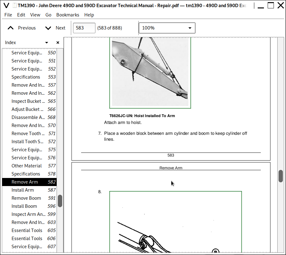
Remove Arm
Install Arm
Remove Boom
Install Boom
Inspect Arm And Boom Pins And Bushings
Remove And Install Bushings
Group 3360: Hydraulic Systems
Essential Tools
Service Equipment And Tools
Other Material
Specifications
Hydraulic Cylinder Bleed Procedure
Release Pressure In Hydraulic System
Remove And Install Hydraulic Pump
Hydraulic Pump Start-Up Procedure
Disassemble Hydraulic Pump
Assemble Hydraulic Pump
Remove And Install Hydraulic Pump Regulator
Disassemble Pump Regulator
Assemble Pump Regulator
Remove And Install Pilot Pump
Disassemble And Assemble Pilot Pump
Remove And Install Solenoid Valve And Pilot Pressure Regulating Valve
Disassemble And Assemble Solenoid Valve And Pilot Pressure Regulating Valve
Remove And Install Engine Speed Mode Selection Cylinders
Disassemble And Assemble Engine Speed Mode Selection Cylinders
Remove And Install Hydraulic Control Valve
Disassemble Hydraulic Control Valve
Assemble Hydraulic Control Valve
Remove And Install Reservoir
Remove And Install Return Filter And Suction Filter
Remove And Install Oil Cooler Restriction Valve
Disassemble And Assemble Oil Cooler Restriction Valve
Remove And Install Oil Cooler Bypass Valve
Disassemble And Assemble Oil Cooler Bypass Valve
Remove And Install Oil Cooler
Remove And Install Bucket Cylinder
Remove And Install Arm Cylinder
Remove And Install Boom Cylinder
Hydraulic Cylinder Bleed Procedure
Disassemble Bucket, Arm And Boom Cylinders
Inspection Of Cylinder Rod
Assemble Bucket, Arm, And Boom Cylinders
Inspection Of Cylinder Pins And Bushings
Remove And Install Auxiliary Shut-Off Valve
Disassemble And Assemble Auxiliary Shut-Off Valve
Remove And Install Propel Function Ler Valve
Disassemble Propel Function Pilot Controller Valve
Assemble Propel Function Pilot Controller Valve
Remove And Install Dig Function Pilot Controller Valve
Disassemble Dig Function Pilot Controller Valve
Assemble Dig Function Pilot Controller Valve
Remove And Install Pilot Shut-Off Valve
Pilot Shut-Off Valve Linkage Adjustment
Disassemble And Assemble Pilot Shut-Off Valve
Disassemble And Assemble Pilot Filter
Inspect Pilot Filter Relief Valve
Remove And Install Flow Control Valve
Disassemble And Assemble Flow Control Valve
Remove And Install Check Valve Block
Disassemble And Assemble Check Valve Block
Section 43: Swing Or Pivoting System
Group 4350: Mechanical Drive Elements
Service Equipment And Tools
Other Material
Specifications
Remove And Install Swing Gearbox
Disassemble And Assemble Swing Gearbox
Remove And Install Swing Bearing
Disassemble And Assemble Swing Bearing
Install Swing Bearing Seals
Group 4360: Hydraulic System
Service Equipment And Tools
Other Material
Specifications
Remove And Install Swing Motor
Disassemble Swing Motor
Assemble Swing Motor
Disassemble And Assemble Crossover Relief Valves
Remove And Install Make-Up Valves
Disassemble And Assemble Swing Brake Release Valve
Section 99: Dealer Fabricated Tools
Group 9900: Dealer Fabricated Tools
DF1036 Propel Gearbox Nut Wrench-490D
DFT1070 Propel Gearbox Nut Wrench-590D
DF1038 Torque Adapter
Rotary Manifold Lifting Tool
ST4920 Track Recoil Spring Disassembly And Assembly Tool
DFT1087 Track Recoil Spring Disassembly And Assembly Guard Tool
John Deere Excavators 490D, 590D Service Repair Manual (TM1390)
![]()