
John Deere 490E Excavator Operation and Test Service Manual (TM1504)

Complete Diagnostics, Operation and Test manual with electrical wiring diagrams for John Deere 490E Excavator, with all the service information to maintain, diagnose, and rebuild like professional mechanics.
John Deere 490E Excavator workshop Operation and Test manual includes:
* Numbered table of contents easy to use so that you can find the information you need fast.
* Detailed sub-steps expand on repair procedure information
* Numbered instructions guide you through every repair procedure step by step.
* Troubleshooting and electrical service procedures are combined with detailed wiring diagrams for ease of use.
* Notes, cautions and warnings throughout each chapter pinpoint critical information.
* Bold figure number help you quickly match illustrations with instructions.
* Detailed illustrations, drawings and photos guide you through every procedure.
* Enlarged inset helps you identify and examine parts in detail.
TM1504 - John Deere 490E Excavator Technical Manual - Operation and Test.PDF
TM1504 - John Deere 490E Excavator Technical Manual - Operation and Test.EPUB
PRODUCT DETAILS:
Total Pages: 860 pages
File Format: PDF (bookmarked, ToC, Searchable, Printable, high quality) & EPUB/MOBI/AZW for Kindle/iPad/iPhone/Android.
Language: English
MAIN SECTIONS
Foreword
General Information
Safety
General Specifications
Torque Values
Fuels And Lubricants
Operational Checkout
Operational Checkout Procedure
Engine
Theory Of Operation
System Operational Checks
Diagnostic Information
Adjustments
Tests
Electrical System
System Information
System Diagrams
References
Power Train
Theory Of Operation
System Operational Checks
Diagnostic Information
Adjustments
Tests
Hydraulic System
Theory Of Operation
System Operational Checks
Diagnostic Information
Adjustments
Tests
tm1504 - 490E Excavator Operation and Tests
Table of Contents
Foreword
Section 9000: General Information
Group 01: Safety
Follow Safe Procedures
Prepare for Emergencies
Prevent Acid Burns
Handle Chemical Products Safely
Handle Fluids Safely-Avoid Fires
Avoid High-Pressure Fluids
Warn Others of Service Work
Support Machine Properly
Operate Only from Operator's Seat
Park Machine Safely
Stay Clear of Moving Parts
Avoid Power Lines
Use Handholds and Steps
Keep Riders Off Machine
Move and Operate Machine Safely
Wear Protective Clothing
Protect Against Flying Debris
Protect Against Noise
Illuminate Work Area Safely
Service Machines Safely
Remove Paint Before Welding or Heating
Avoid Heating Near Pressurized Fluid Lines
Beware of Exhaust Fumes
Use Proper Lifting Equipment
Service Cooling System Safely
Dispose of Waste Properly
Work in a Clean Area
Use Tools Properly
Replace Safety Signs
Live With Safety
Group 02: General Specifications
490E
490E Drain And Refill Capacities
Group 03: Torque Values
Unified Inch Bolt and Cap Screw Torque Values
Metric Bolt and Cap Screw Torque Values
Additional Metric Cap Screw Torque Values
Service Recommendations for O-Ring Boss Fittings
Service Recommendations for Flat Face O-Ring Seal Fittings
Service Recommendations for 37° Flare and 30° Cone Seat Connectors
Service Recommendations For Flared Connections-Straight or Tapered Threads
Service Recommendations For Inch Series Four Bolt Flange Fittings
Service Recommendations for Metric Series Four Bolt Flange Fitting
Group 04: Fuels And Lubricants
Fuel Specifications
Engine Oil
Hydraulic Oil
Swing Gearbox, Propel Gearbox and Pump Gearbox Oils
Track Roller, Front Idler, And Carrier Roller Oil
Track Adjuster, Working Tool Pivot, Swing Bearing, And Swing Bearing Gear Grease
Section 9005: Operational Checkout
Group 10: Operational Checkout Procedure
Operational Checkout Record Sheet-490E
Operational Checkout
Section 9010: Engine
Group 05: Theory Of Operation
4045 John Deere Engine-Use CTM8
General Engine Description
Engine-Sectional View
Fan Drive Operation
Engine Speed Control System Operation
Group 10: System Operational Checks
4045 John Deere Engine-Use CTM8
Engine Operational Checks
Group 15: Diagnostic Information
4045 John Deere Engine-Use CTM8
Diagnose Engine Malfunctions
Group 20: Adjustments
4045 John Deere Engine-Use CTM8
JT05801 Clamp-On Electronic Tachometer Installation
Engine Speed And Control Linkage Adjustment
Group 25: Tests
4045 John Deere Engine-Use CTM8
Fuel Line Leakage Test
Air Filter Restriction Indicator Switch Test
Air Intake System Leakage Test
Radiator Air Flow Test
JT05529 Air Flow Meter Test Record
Section 9015: Electrical System
Group 05: System Information
Visually Inspect Electrical System
Electrical Circuit Malfunctions
High Resistance Circuit
Open Circuit
Grounded Circuit
Shorted Circuit
Multimeter
Seven Step Electrical Test Procedure
Wiring Diagram And Schematic Information
Reading A System Functional Schematic
Reading A Wiring Diagram
Electrical Schematic Symbols
Group 10: System Diagrams
Replacing Fuses
Fuse (Blade-Type) Color Codes
Fuse Specifications
Switch Specifications
Component Identification Table
Wiring And Schematic Diagrams Legend
Component Location Diagram
System Functional Schematic
Engine Harness (W5) Wiring Diagram
Cab Harness (W6) Wiring Diagram
Power Circuit Operational Information
Power Circuit Theory Of Operation
Power Circuit Schematic
Charging Circuit Operational Information
Charging Circuit Theory Of Operation
Charging Circuit Schematic
Windshield Wiper And Washer Circuit Operational Information
Windshield Wiper And Washer Circuit Theory Of Operation
Windshield Wiper And Washer Circuit Schematic
Switch Panel 1 Circuit Operational Information
Switch Panel 1 Theory Of Operation
Switch Panel 1 Circuit Schematic
Switch Panel 2 Circuit Operational Information
Switch Panel 2 Theory Of Operation
Switch Panel 2 Circuit Schematic
Light Circuit Operational Information
Light Circuit Theory Of Operation
Light Circuit Schematic
Horn, Dome Light, Cigar Lighter And Heater Circuits Operational Information
Horn, Dome Light, Cigar Lighter And Heater Circuits Theory Of Operation
Horn, Dome Light, Cigarette Lighter And Heater Circuits Schematic
Monitor Circuit Specifications
Monitor Circuit Operational Information
Monitor Circuit Theory Of Operation
Monitor Circuit Schematic
Auto Idle Circuit Operational Information
Auto Idle Circuit Theory Of Operation
Auto Idle Circuit Schematic
Warm-Up Circuit Operational Information
Warm-Up Circuit Theory Of Operation
Hydraulic Warm-Up Circuit Schematic
Pump And Valve Controller Circuit Operational Information
Pump And Valve Controller Circuit Theory Of Operation
Pump And Valve Controller Circuit Schematic
Engine Controller Circuit Operational Information
Engine Controller Circuit Theory Of Operation
Engine Controller Circuit Schematic
Start Aid And Travel Alarm Circuit Operational Information
Start Aid And Propel Alarm Circuit Theory Of Operation
Start Aid And Propel Alarm Circuit Schematic
Group 20: References
Monitor And Switch Panels
Monitor Panel
Switch Panel 1
Switch Panel 2
Resetting Engine Controller (EC)
Electrical Component Identification
Alternator Voltage Output Test-Delco
Alternator Operation-40 Amp Delco Remy
Replacing Batteries
Battery Operation
Diagnose Battery Malfunctions
Check Battery Electrolyte Level And Terminals
Procedure For Testing Batteries
Using Booster Batteries-24 Volt System
Engine Speed And Control Linkage Adjustment
Electronic Control Bypass Procedure
Hydraulic Pump Angle Sensor (A Sensor) Mechanical Check Diagnostic Procedure
Hydraulic Pump Angle Sensor (A Sensor) Adjustment
Troubleshooting Pump And Valve Controller (PVC)
Troubleshooting Engine Controller (EC)
Engine Control Sensor (EC Sensor) Harness Test
Connecting Engine Controller (EC) And Pump And Valve Controller (PVC) Harness Connector
Disconnect Tab Retainer Connectors
Disconnecting Spring Wire Retainer Connectors
Connector Pin Location And Numbers
Section 9020: Power Train
Group 05: Theory Of Operation
Power Train Components
Propel System Operation
Propel Pilot Circuit Operation
Propel Pilot Controller Operation-Neutral
Propel Pilot Check Valve Block Operation-Forward
Propel Control Valve Operation
Variable Pressure Compensator Valve Operation
Propel Proportional Solenoid Valve Operation
Propel Speed Control System Operation
Propel Speed Change Solenoid Valve Operation
Rotary Manifold Operation
Propel Brake Valve Operation
Propel Brake Pressure Reducing Valve Operation
Counterbalance Valve Operation-Neutral
Counterbalance Valve Operation-Propel
Counterbalance Valve Operation-Braking
Propel Motor Crossover Relief Valve Operation
Propel Motor Operation
Propel Speed Operation-Super Low And Normal
Propel Motor Operation-Max. Speed
Charge Valve Operation-Normal Maximum Speed
Charge Valve Maximum Speed Operation-Braking
Propel Gearbox Operation
Track Adjuster Operation
Group 10: System Operational Checks
Power Train Operational Checks
Group 15: Diagnostic Information
Diagnose Undercarriage Components Malfunctions
Diagnose Propel System Malfunctions
Measure Track Chain Bushing Wear
Measure Track Chain Pitch
Measure Track Chain Link Wear
Measure Track Shoe Grouser Wear
Measure Lower Track Roller Wear
Measure Front Idler Wear
Measure Upper Track Roller Wear
Propel System Component Location
Group 20: Adjustments
Adjust Track Sag
Propel Speed Cycle Time
Group 25: Tests
JT07058 Diagnostic Computer Operating Procedure
JT07059 Diagnostic Computer Function
JT05801 Clamp-On Electronic Tachometer Installation
JT05800 Digital Thermometer Installation
Hydraulic System Warm-Up Procedure
Propel Motor Start-Up Procedure
Engine Speed Programming Procedure After Battery Disconnection
Propel Motor Crossover Relief Valve Test And Adjustment
Propel Speed Change Solenoid Valve Test And Adjustment
Propel Proportional Solenoid Valve Test And Adjustment
Propel Motor Operating Leakage Test
Swing Bearing Wobble Test
Section 9025: Hydraulic System
Group 05: Theory Of Operation
Hydraulic System
Control Systems Operation
Switch Panel 2
Engine (EC), Pump And Valve (PVC) Controllers
Engine Control Circuit
Engine Power Modes
Hydraulic System Block Diagram
Load Sense System-Control Valves In Neutral
Load Sense System-Single Function Actuated
Load Sense System-Function Held Over Relief
Pump Control-Speed Sensing
Flow Dividing Control System
Work Mode Chart
Propel Speed Control System
Swing Brake Release Circuit Operation
Swing Stop Cushion Valve Circuit Operation
Warm-Up Control Circuit
Pilot Circuit Operation
Pilot Pump Operation
Pilot Filter Operation
Solenoid Valve Assembly Operation
Pilot Pressure Regulating Valve Operation
Pilot Pressure Reducing Valve Operation
Proportional Solenoid Valve Operation
Pilot Shut-Off Valve Operation
Pilot Controller Operation-Neutral
Pilot Controller Operation-Metering
Pilot Controller Operation-Full Stroke
Pilot Operation Of Main Control Valve
Dig Function Pilot Controller Check Valve Operation
Flow Regulator Valve Operation
Warm-Up Circuit Operation
Main Hydraulic Pump Operation
Main Hydraulic Pump Displacement Solenoid Valves Operation
Main Hydraulic Pump Control Operation
Main Hydraulic Pump Operation-Maximum Displacement
Main Hydraulic Pump Operation-Minimum Displacement
Main Hydraulic Pump Angle Sensor (A Sensor) Operation
Main Hydraulic Pump And Drive Gearbox-Serial No. (025000-)
Main Control Valve Operation
Control Valve Inlet Section Operation
Surge Relief Valve Operation (Serial No. -024999) System Relief Valve Operation (Serial No. 025000- )
System Relief Valve And Unloading Valve Operation-Neutral
System Relief Valve And Unloading Valve Operation-Activated
Circuit Relief Valve Operation
Differential Pressure Sensor Operation
Variable Pressure Compensator Valves Operation
Auxiliary Valve Operation
Arm, Boom, And Bucket Valve Operation
Anti-Drift Valve Operation
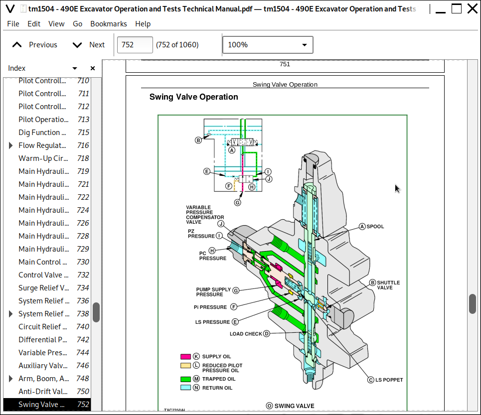
Swing Valve Operation
Shuttle Valve Operation
Combined Function Operation
Swing Motor And Brake Operation
Swing Motor Cover Operation-Start Of Swing
Swing Motor Cover Operation-Normal Swing
Swing Motor Cover Operation-Stopping
Swing Brake Release Solenoid Valve Operation
Swing Stop Cushion Valve Operation
Swing Stop Cushion Valve Operation-Swinging
Swing Gearbox Operation
Cylinder Operation
Return Filter Operation
Suction Screen Operation
Oil Cooler Operation
Pump Inlet And Delivery Circuits Operation
Return Circuit Operation
Drain Circuit Operation
Group 10: System Operational Checks
Hydraulic Operational Checks
Group 15: Diagnostic Information
Diagnostic Procedure
JT07058 Diagnostic Computer Operating Procedure
JT07059 Diagnostic Computer Function
Troubleshooting Differential Pressure Sensor (DP Sensor)
Troubleshooting Pump And Valve Controller (PVC)
Troubleshooting Engine Controller (EC)
Troubleshooting Engine Speed Sensor (N Sensor)
Troubleshooting Pump Displacement Angle Sensor (A Sensor)
Troubleshooting Pressure Sensor (P Sensor)
Troubleshooting Engine Control Sensor (EC Sensor)
Troubleshooting Hydraulic Oil Temperature Sensor (T Sensor)
Troubleshooting Boom Up Pilot Pressure Sensor (BPI Sensor)-Serial No. (025000- )
Troubleshooting Arm In Pressure Sensor (ABP Sensor)-Serial No. (025000- )
Troubleshooting Pump Displacement Solenoid Valve (PDSV)
Troubleshooting Proportional Solenoid Valve
Troubleshooting Propel Speed Change Solenoid Valve
Troubleshooting Swing Brake Release Solenoid Valve
Troubleshooting Swing Stop Cushion Valve
Troubleshooting Engine Control Motor (EC Motor)
Hydraulic Pump Angle Sensor (A Sensor) Mechanical Check Diagnostic Procedure
Introduction To Flow Charts
Diagnose Hydraulic System Malfunctions
Diagnose Pilot Circuit Malfunctions
Diagnose Dig Circuit Malfunctions
Diagnose Swing Circuit Malfunctions
Pilot Circuit Component Location
Hydraulic System Component Location
Pilot System SAE Pattern
Pilot System John Deere Pattern
Group 20: Adjustments
Pilot Shut-Off Valve Linkage Adjustment
Group 25: Tests
JT07058 Diagnostic Computer Operating Procedure
JT07058 Diagnostic Computer Initial Setup
Connecting JT07058 Diagnostic Computer To Machine
Begin JT07058 Diagnostic Computer Function
JT07059 Diagnostic Computer Function
Retry Procedure A
Retry Procedure B
Self Diagnostic Function Fault Codes For Engine Controller (EC)
Self Diagnostic Function Fault Codes For Pump And Valve Controller (PVC)
Monitor Data Function Display List And Description
Component Abbreviations And Location
Cross Reference To Monitor Data Function And Display Symbol
Reading Fault Codes Without JT07058 Diagnostic Computer
Reading Fault Codes With JT07058 Diagnostic Computer
Monitor Data Function Worksheet-490E
Example Of Monitor Data Function Worksheet
JT05801 Clamp-On Electronic Tachometer Installation
JT05800 Digital Thermometer Installation
Hydraulic System Warm-Up Procedure
Hydraulic Pump Start-Up Procedure
Swing Motor Start-Up Procedure
Swing Gearbox Start-Up Procedure
Hydraulic Oil Filter Inspection Procedure
Engine Speed Programming Procedure After Battery Disconnection
Hydraulic Oil Cleanup Procedure Using Portable Filter Caddy
Cycle Time Test
Proportional Solenoid Valve Harness Test
Swing Brake Solenoid Valve Harness Test
Pump Displacement Solenoid Valve Harness Test
Swing Stop Cushion Valve Harness Test
Engine Control Motor (EC Motor) Harness Test
Differential Pressure Sensor Voltage Test And Adjustment
Engine Control Sensor (EC Sensor) Test
Miscellaneous Harness Test
Pilot Pressure Regulating Valve Test And Adjustment
Pilot Pressure Reducing Valve Test And Adjustment
Surge Relief Valve Test And Adjustment-Serial No. ( -024999)
System Relief Valve Test And Adjustment-(Serial No. -024999)
System Relief Valve Test And Adjustment-(Serial No. 025000- )
Circuit Relief Valve Test And Adjustment
Proportional Solenoid Valve (PSV) Test And Adjustment
Swing Motor Crossover Relief Valve Test And Adjustment
Hydraulic Pump Flow Test
Engine Power Or Hydraulic Pump Test Using Flow Meter Method
Pilot Pump Flow Test
Arm, Boom, And Bucket Cylinder Drift Test
Swing Motor Leakage Test
Oil Cooler Flow And Pressure Drop Test
John Deere 490E Excavator Operation and Test Service Manual (TM1504)
![]()