
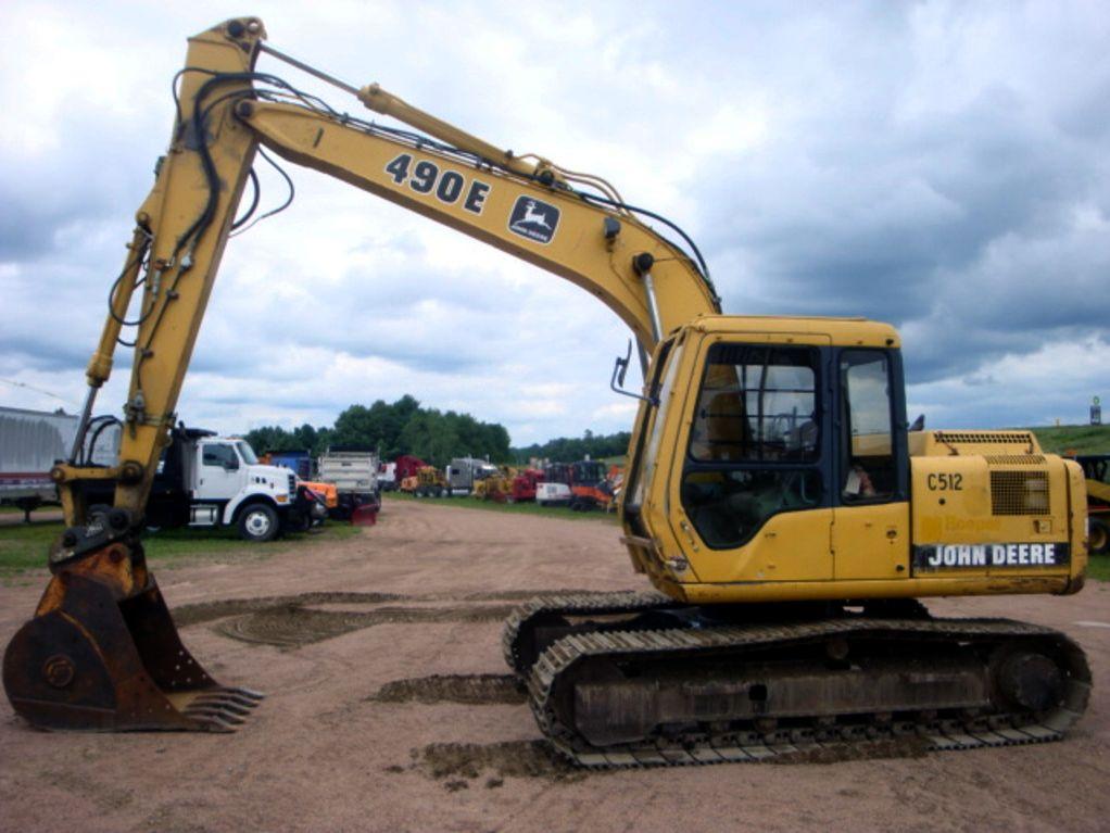
John Deere 490E Excavator Service Repair Manual (TM1505)

Complete service repair manual for John Deere 490E Excavator, with all the service information to maintain, repair, and rebuild like professional mechanics.
John Deere 490E Excavator workshop service & repair manual includes:
* Numbered table of contents easy to use so that you can find the information you need fast.
* Detailed sub-steps expand on repair procedure information
* Numbered instructions guide you through every repair procedure step by step.
* Notes, cautions and warnings throughout each chapter pinpoint critical information.
* Bold figure number help you quickly match illustrations with instructions.
* Detailed illustrations, drawings and photos guide you through every procedure.
* Enlarged inset helps you identify and examine parts in detail.
TM1505 - John Deere 490E Excavator Technical Manual - Repair.PDF
TM1505 - John Deere 490E Excavator Technical Manual - Repair.EPUB
PRODUCT DETAILS:
Total Pages: 664 pages
File Format: PDF (bookmarked, ToC, Searchable, Printable, high quality) & EPUB/MOBI/AZW for Kindle/iPad/iPhone/Android.
Language: English
TABLE OF CONTENTS................1
Section 00: General Information................14
Group 0001: Safety................14
Follow Safe Procedures................17
Prepare for Emergencies................18
Prevent Acid Burns................19
Handle Chemical Products Safely................21
Handle Fluids Safely-Avoid Fires................22
Avoid High-Pressure Fluids................23
Warn Others of Service Work................24
Support Machine Properly................25
Operate Only from Operator's Seat................26
Park Machine Safely................27
Stay Clear of Moving Parts................28
Avoid Power Lines................29
Use Handholds and Steps................30
Keep Riders Off Machine................31
Move and Operate Machine Safely................32
Wear Protective Clothing................33
Protect Against Flying Debris................34
Protect Against Noise................35
Illuminate Work Area Safely................36
Service Machines Safely................37
Remove Paint Before Welding or Heating................38
Avoid Heating Near Pressurized Fluid Lines................39
Beware of Exhaust Fumes................40
Use Proper Lifting Equipment................41
Service Cooling System Safely................42
Dispose of Waste Properly................43
Work in a Clean Area................44
Use Tools Properly................45
Replace Safety Signs................46
Live With Safety................47
Group 0002: General Specifications................670
490E................15
490E Drain And Refill Capacities................15
Group 0003: Torque Values................15
Unified Inch Bolt and Cap Screw Torque Values................54
Metric Bolt and Cap Screw Torque Values................55
Additional Metric Cap Screw Torque Values................56
Service Recommendations for O-Ring Boss Fittings................58
Service Recommendations for Flat Face O-Ring Seal Fittings................60
Service Recommendations for 37° Flare and 30° Cone Seat Connectors................62
Service Recommendations For Flared Connections-Straight or Tapered Threads................64
Service Recommendations For Inch Series Four Bolt Flange Fittings................66
Service Recommendations for Metric Series Four Bolt Flange Fitting................68
Group 0004: Fuels and Lubricants................15
Fuel Specifications................670
Engine Oil................72
Hydraulic Oil................74
Swing Gearbox, Propel Gearbox and Pump Gearbox Oils................75
Track Roller, Front Idler, And Carrier Roller Oil................76
Track Adjuster, Working Tool Pivot, Swing Bearing, And Swing Bearing Gear Grease................77
Section 01: Tracks................78
Group 0130: Track System................78
Service Equipment and Tools................634
Other Material................635
Specifications................670
Measure Lower Track Roller Wear................83
Remove and Install Lower Track Roller................84
Disassemble and Assemble Lower Track Roller................86
Test Lower Track Roller for Oil Leakage................89
Measure Upper Track Roller Wear................90
Remove and Install Upper Track Roller................91
Disassemble and Assemble Upper Track Roller................93
Inspect Metal Face Seals................153
Measure Track Shoe Grouser Wear................98
Remove and Install Track Shoe................99
Measure Track Chain Link Wear................101
Measure Track Chain Bushing Wear................102
Measure Track Chain Pitch................103
Remove Track Chain................104
Install Track Chain................107
Disassemble and Assemble Track Chain................110
Disassemble and Assemble Track Chain to Replace Broken Part................112
Adjust Track Sag................115
Remove and Install Sprocket................117
Measure Front Idler Wear................119
Remove and Install Front Idler................120
Disassemble Front Idler................121
Assemble Front Idler................123
Test Front Idler for Oil Leakage................125
Remove and Install Track Adjuster Cylinder and Recoil Spring................127
Disassemble and Assemble Track Adjuster Recoil Spring................130
Disassemble and Assemble Track Adjuster Cylinder................135
Section 02: Axles and Suspension Systems................138
Group 0250: Axle Shaft, Bearings, and Reduction Gears................138
Service Equipment and Tools................634
Other Material................635
Specifications................670
Towing Machine................143
Remove and Install Propel Gearbox................145
Disassemble Propel Gearbox................148
Inspect Metal Face Seals................153
Disassemble and Assemble First Planet Carrier................155
Disassemble and Assemble Second Planet Carrier................156
Assemble Propel Gearbox................157
Group 0260: Hydraulic System................138
Service Equipment and Tools................634
Other Material................635
Specifications................670
Remove and Install Propel Motor and Brake................166
Propel Motor Start-Up Procedure................169
Disassemble Propel Motor and Brake................170
Assemble Propel Motor and Brake................174
Disassemble and Assemble Propel Motor Brake Valve Housing................179
Remove and Install Rotary Manifold................190
Disassemble and Assemble Rotary Manifold................194
Rotary Manifold Air Test................197
Section 04: Engine................198
Group 0400: Removal and Installation................198
4045 John Deere Engine-Use CTM8................198
Special or Essential Tools................459
Service Equipment and Tools................634
Other Material................635
Specifications................670
Remove Engine................206
Install Engine................211
Remove and Install Oil Pan................216
Removing DB4 Fuel Injection Pump................219
Installing DB4 Fuel Injection Pump................223
JT07158 TIME TRAC TIME TRAC is a registered trademark of the Stanadyne Automotive Corp. Installation................198
Bleed Fuel System................229
Adjust Engine Valve Lash (Clearance)................230
Remove and Install Starter................233
Section 05: Engine Auxiliary Systems................235
Group 0505: Cold Weather Starting Aids................235
Other Material................635
Specifications................670
Remove and Install Starting Aid Solenoid and Nozzle................239
Remove and Install Engine Coolant Heater................241
Group 0510: Cooling System................235
Specifications................670
Remove and Install Fan, Shroud, and Guards................245
Remove and Install Radiator................247
Remove and Install Fan Belt................250
Group 0515: Speed Controls................235
Service Equipment and Tools................634
Other Material................635
Specifications................670
Remove and Install Engine Speed and Control Linkage................255
Engine Speed and Control Linkage Adjustment................257
Remove and Install Engine Control (EC) Motor and Sensor................260
Disassemble and Assemble Engine Control (EC) Motor and Sensor................262
Group 0520: Intake System................235
Special or Essential Tools................459
Service Equipment and Tools................634
Specifications................670
Remove and Install Air Cleaner................269
Air Intake System Leakage Test................270
Group 0560: External Fuel Supply Systems................235
Other Material................635
Specifications................670
Remove and Install Fuel Tank................274
Remove and Install Water Separator Filter................276
Disassemble and Assemble Water Separator Filter................277
Section 07: Dampener Drive (Flex Coupling)................279
Group 0752: Elements................279
Specifications................670
Remove and Install Dampener Drive (Flex Coupling)................282
Section 16: Electrical System................287
Group 1671: Batteries, Support, and Cables................287
Service Equipment and Tools................634
Specifications................670
Handle Batteries Safely................292
Procedure for Testing Batteries................293
Checking Electrolyte Specific Gravity................294
Check Battery Electrolyte Level and Terminals................297
Using Booster Batteries-24-Volt System................300
Charge Battery................302
Batteries Remove and Install................305
Adding 12-Volt Accessories................307
Group 1672: Alternator, Regulator, and Charging System Wiring................287
Alternators and Starting Motors-Use CTM77................309
Specifications................670
Remove and Install Alternator................311
Group 1674: Wiring Harness and Switches................287
Special or Essential Tools................459
Front Chassis Electrical Component Identification................315
Cab Electrical Component Identification................317
Hydraulic Electrical Component Identification................320
Engine Electrical Component Identification................322
Connecting Engine Controller (EC) and Pump and Valve Controller (PVC) Harness Connector................352
Disconnecting Spring Wire Retainer Connectors................325
Disconnecting Tab Retainer Connectors................326
Replacing Fuses................327
Fuse (Blade-Type) Color Codes................330
Remove and Install Cab Ground Straps................331
Remove and Install Starter Switch................332
Remove and Install Dome Light Switch................334
Remove and Install Propel Alarm Cancel Switch and Start Aid Switch................335
Replace DEUTSCH DEUTSCH is a trademark of the Deutsch Co. Connectors................287
Install DEUTSCH DEUTSCH is a trademark of the Deutsch Co. Contact................288
Replace WEATHER PACK WEATHER PACK is a trademark of Packard Electric Connector................288
Install WEATHER PACK WEATHER PACK is a trademark of Packard Electric Contact................288
Remove Connector Body From Blade Terminals................345
Group 1675: System Controls................288
Welding on Machine................435
Connecting Engine Controller (EC) and Pump and Valve Controller (PVC) Harness Connector................352
Remove and Install Pump and Valve Controller (PVC)................353
Remove and Install Monitor Controller................355
Group 1676: Instruments and Indicators................288
Replace Monitor Panel Bulbs................357
Remove and Install Monitor Panel................358
Remove and Install Switch Panel 1................360
Remove and Install Hour Meter, Coolant Temperature and Fuel Level Gauges................361
Replace Switch Panel 2 Bulb................363
Remove and Install Switch Panel 2................364
Section 17: Frame or Supporting Structure................366
Group 1740: Frame Installation................366
Specifications................670
Welding on Machine................435
Welding Repair of Major Structure................372
Group 1749: Chassis Weights................366
Service Equipment and Tools................634
Specifications................670
Remove and Install Counterweight................377
Section 18: Operator's Station................379
Group 1800: Removal and Installation................379
Specifications................670
Remove and Install Cab................382
Group 1810: Operator Enclosure................379
Service Equipment and Tools................634
Other Material................635
Remove and Install Windowpane and Two Piece Molding................390
Remove and Install Windowpane and One Piece Molding................392
Remove and Install Sliding Windows................393
Windowpane Dimensions................395
Group 1821: Seat and Seat Belt................379
Specifications................670
Remove and Install Seat................399
Disassemble and Assemble Seat (Early Machine)................401
Disassemble and Assemble Seat Stand (Early Machine)................403
Group 1830: Heating and Air Conditioning................379
Remove and Install Blower Motor................408
Remove and Install Heater Core and Blower Motor Relay................410
Section 20: Safety and Convenience................411
Group 2004: Horn and Warning Devices................411
Remove and Install Travel Alarm................413
Changing Travel Alarm Volume................414
Section 33: Excavator................416
Group 3302: Bucket................416
Specifications................670
Replacing Bucket Teeth................421
Replacing Bucket Tooth Tip-Heavy-Duty Bucket................423
Remove and Install Tooth Shank................425
Remove and Install Bucket and Linkage................428
Adjust Bucket Linkage................433
Welding on Machine................435
Replace Welded Bucket Cutting Edges................437
Repair Cracked Cutting Edge................438
Group 3340: Frames................416
Service Equipment and Tools................634
Specifications................670
Remove and Install Arm................443
Remove and Install Boom................449
Inspect Arm and Boom Pins and Bushings................454
Remove and Install Bushings and Seals................456
Group 3360: Hydraulic System................416
Special or Essential Tools................459
Service Equipment and Tools................634
Other Material................635
Specifications................670
Hydraulic Cylinder Bleed Procedure................597
Release Pressure in Hydraulic System................466
Hydraulic Oil Cleanup Procedure Using Portable Filter Caddy................468
Remove and Install Hydraulic Pump................470
Hydraulic Pump Start-Up Procedure................474
Disassemble Hydraulic Pump................475
Assemble Hydraulic Pump................482
Remove and Install Hydraulic Pump Displacement Solenoid Valve................496
Remove and Install Engine Speed Sensor (S.N. -024999)................498
Remove and Install Engine Speed Sensor (S.N. 025000-)................499
Remove and Install Hydraulic Pump Angle Sensor (A Sensor)................500
Hydraulic Pump Angle Sensor (A Sensor) Adjustment................503
Remove and Install Pilot Pump (S.N. -024999)................505
Remove and Install Pilot Pump (S.N. 025000-)................506
Disassemble and Assemble Pilot Pump................508
Remove and Install Pilot Filter................512
Hydraulic Oil Filter Inspection Procedure................514
Remove and Install Proportional Solenoid Valve................515
Disassemble and Assemble Proportional Solenoid Valve................518
Remove and Install Pilot Pressure Regulating Valve................522
Remove and Install Pilot Pressure Reducing Valve................523
Remove and Install Pilot Shut-Off Valve................524
Disassemble and Assemble Pilot Shut-Off Valve................526
Pilot Shut-Off Valve Linkage Adjustment................528
Remove and Install Dig Function Pilot Controller................530
Disassemble and Assemble Dig Function Pilot Controller................534
Remove and Install Dig Function Pilot Controller Check Valve................537
Disassemble and Assemble Dig Function Pilot Controller Check Valve................539
Remove and Install Dig Function Pilot Flow Regulator Valve................540
Disassemble and Assemble Dig Function Pilot Flow Regulator Valve................542
Remove and Install Propel Pilot Controller................544
Disassemble and Assemble Propel Pilot Controller................546
Remove and Install Propel Pilot Check Valve Block................550
Disassemble and Assemble Propel Pilot Check Valve Block................552
Remove and Install Main Control Valve................553
Disassemble and Assemble Main Control Valve................558
Remove and Install Differential Pressure Sensor................572
Remove and Install Surge Relief Valve (S.N. -024999) System Relief Valve (S.N. 025000-)................573
Disassemble and Assemble Surge Relief Valve (S.N. -024999) System Relief Valve (S.N. 025000-)................574
Remove and Install System Relief Valve and Unloading Valve (S.N. -024999)................576
Disassemble and Assemble System Relief Valve and Unloading Valve (S.N. -024999)................577
Remove and Install Circuit Relief and Anti-Cavitation Valve................579
Disassemble and Assemble Circuit Relief and Anti-Cavitation Valve................580
Remove and Install Variable Pressure Compensator Valve................583
Disassemble and Assemble Variable Pressure Compensator Valve................585
Remove and Install Holding Valve................586
Remove and Install Shuttle Valve................587
Remove and Install Arm in Pressure Sensor (S.N. 025000-)................589
Remove and Install Boom Cylinder................590
Remove and Install Arm Cylinder................593
Remove and Install Bucket Cylinder................595
Hydraulic Cylinder Bleed Procedure................597
Disassemble Bucket, Arm, or Boom Cylinder................598
Assemble Bucket, Arm, or Boom Cylinder................604
Remove and Install Hydraulic Oil Cooler................618
Remove and Install Hydraulic Oil Cooler Bypass Valve................621
Remove and Install Swing Make-Up Restriction Valve................623
Remove and Install Return Filter and Bypass Valve................625
Remove and Install Reservoir................627
Disassemble and Assemble Reservoir................630
Section 43: Swing Rotation or Pivoting System................632
Group 4350: Mechanical Drive Elements................632
Service Equipment and Tools................634
Other Material................635
Specifications................670
Remove and Install Swing Gearbox................637
Swing Gearbox Start-Up Procedure................639
Disassemble and Assemble Swing Gearbox................640
Remove Upperstructure................649
Install Upperstructure................657
Remove and Install Swing Bearing................661
Disassemble and Assemble Swing Bearing................663
Install Swing Bearing Upper Seal................667
Install Swing Bearing Lower Seal................668
Group 4360: Hydraulic System................632
Specifications................670
Remove and Install Swing Motor and Brake................671
Swing Motor Start-Up Procedure................673
Disassemble Swing Motor and Brake................674
Assemble Swing Motor and Brake................679
Disassemble and Assemble Swing Motor Valve Housing and Cover................684
Disassemble and Assemble Swing Relief Valve................686
Remove and Install Swing Stop Cushion Valve................689
Disassemble and Assemble Swing Stop Cushion Valve................691
Disassemble and Assemble Swing Brake Release Solenoid Valve................696
Section 99: Dealer Fabricated Tools................698
Group 9900: Dealer Fabricated Tools................698
ST4920 Track Recoil Spring Disassembly and Assembly Tool................704
DFT1087 Track Recoil Spring Disassembly and Assembly Guard Tool................709
DFT1112 Spacer................710
DF1036A Propel Gearbox Nut Wrench................711
DFT1109 Holding Bar................712
Rotary Manifold Lifting Tool................713
DFT1089 Barrel Support................714
DFT1113 Guide Pin................716
DFT1119 Pump Support................717
John Deere 490E Excavator Service Repair Manual (TM1505)
![]()