
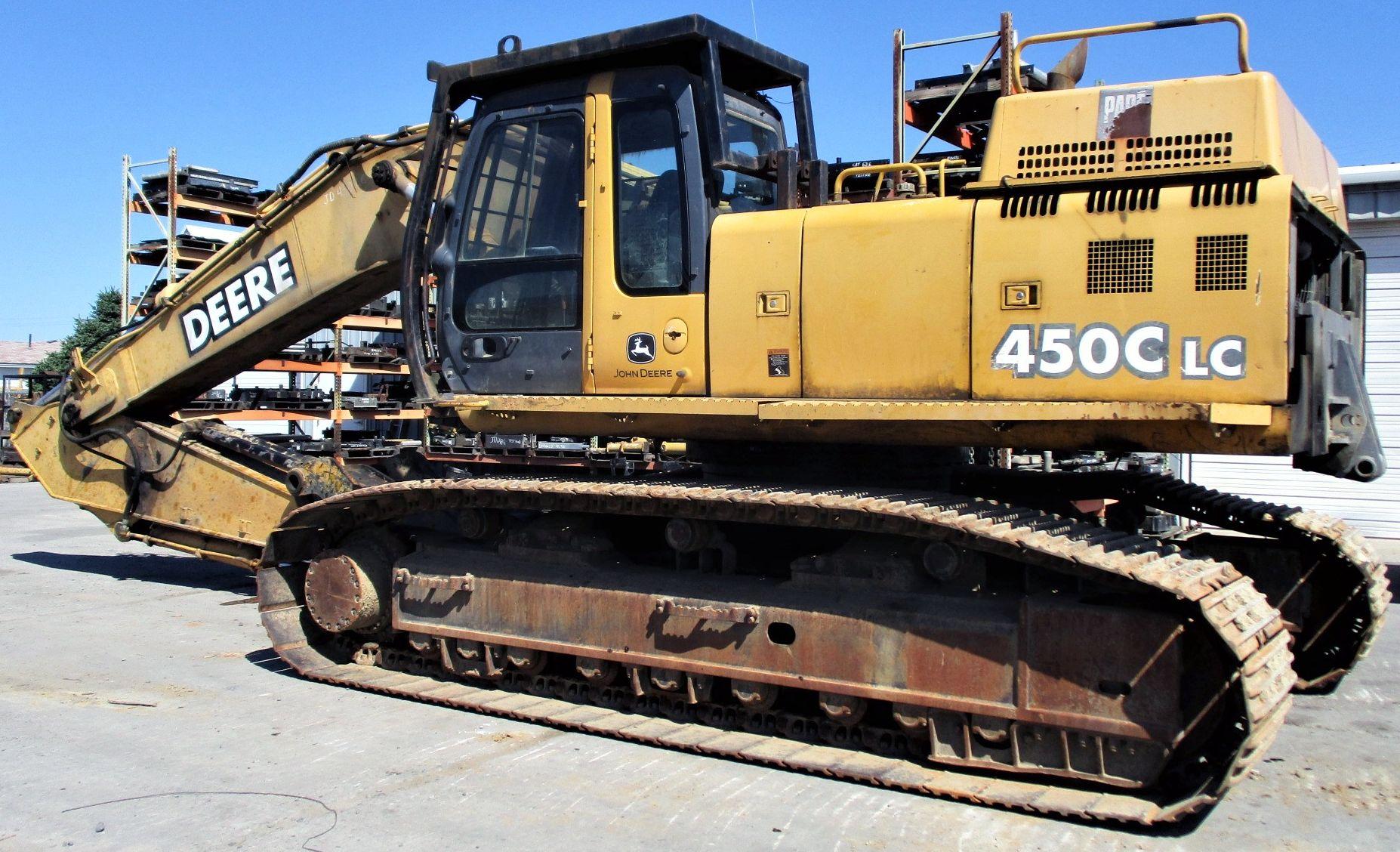
John Deere 450CLC Excavator Service Repair Manual (TM1925)

Complete service repair manual for John Deere 450CLC Excavator, with technical information to maintain, repair, and service like professional mechanics.
John Deere 450CLC Excavators workshop service & repair manual includes:
* Numbered table of contents easy to use so that you can find the information you need fast.
* Detailed sub-steps expand on repair procedure information
* Numbered instructions guide you through every repair procedure step by step.
* Notes, cautions and warnings throughout each chapter pinpoint critical information.
* Bold figure number help you quickly match illustrations with instructions.
* Detailed illustrations, drawings and photos guide you through every procedure.
* Enlarged inset helps you identify and examine parts in detail.
TM1925 - John Deere 450CLC Excavator Technical Manual - Repair.PDF
TM1925 - John Deere 450CLC Excavator Technical Manual - Repair.EPUB
PRODUCT DETAILS:
Total Pages: 454 pages
File Format: PDF/EPUB/MOBI/AZW (PC/Mac/Android/Kindle/iPhone/iPad; bookmarked, ToC, Searchable, Printable)
Language: English
MAIN SECTIONS
Foreword
General Information
Predelivery Assembly Instructions
Tracks
Track System
Axles and Suspension Systems (Propel)
Axle Shaft, Bearings and Reduction Gears
Hydraulic System
Engine
Removal and Installation
Engine Auxiliary Systems
Cooling System
Intake System
External Fuel Supply Systems
Connector Drive
Elements
Electrical System
Batteries, Support and Cables
Wiring Harness and Switches
System Controls
Frame, Chassis or Supporting Structure
Chassis Weights
Operator`s Station
Removal and Installation
Operator Enclosure
Seat and Seat Belt
Heater and Air Conditioning
Safety, Convenience, and Miscellaneous
Horn and Warning Devices
Excavator
Bucket
Frames
Hydraulic System
Swing or Pivoting System
Mechanical Drive Elements
Hydraulic System
Dealer Fabricated Tools
tm1925 - 450CLC Excavator
Table of Contents
Technical Information Feedback Form
Section 00: General Information
Group 06: Predelivery Assembly Instructions
Specifications
Install Boom, Arm, Bucket and Counterweight
Adjust Bucket Linkage
Attach Windshield Wiper
Track Gauge Work Position Adjustment
Track Gauge Transport Position Adjustment
Check Hydraulic Oil Level
Lubricate Working Tool Pivots
Install Counterweight
Section 01: Tracks
Group 0130: Track System
Service Equipment and Tools
Other Material
Specifications
Track Roller
Inspect Metal Face Seals
Track Carrier Roller
Remove and Install Track Shoe
Track Chain
Remove and Install Sprocket
Front Idler
Track Adjuster Cylinder and Recoil Spring
Disassemble and Assemble Track Adjuster Cylinder
Section 02: Axles and Suspension Systems (Propel)
Group 0250: Axle Shaft, Bearings and Reduction Gears
Essential Tools
Service Equipment and Tools
Other Material
Specifications
Propel Gearbox
Group 0260: Hydraulic System
Essential Tools
Service Equipment and Tools
Other Material
Specifications
Propel Motor and Brake
Propel Motor Start-Up Procedure
Remove and Install Rotary Manifold
Section 04: Engine
Group 0400: Removal and Installation
Essential Tools
Service Equipment and Tools
Other Material
Specifications
Remove and Install Engine
Section 05: Engine Auxiliary Systems
Group 0510: Cooling System
Specifications
Remove and Install Fan, Shroud, and Guard
Remove and Install Radiator
Group 0520: Intake System
Remove and Install Air Cleaner and Piping
Group 0560: External Fuel Supply Systems
Specifications
Remove and Install Fuel Tank
Section 07: Connector Drive
Group 0752: Elements
Specifications
Remove and Install Connector Drive Coupling
Section 16: Electrical System
Group 1671: Batteries, Support and Cables
Specifications
Remove and Install Batteries
Group 1674: Wiring Harness and Switches
Remove and Install Key Switch
Group 1675: System Controls
Remove and Install Engine Control Unit (ECU)
Remove and Install Pump and Valve Controller (PVC)
Remove and Install Monitor Controller
Section 17: Frame, Chassis or Supporting Structure
Group 1749: Chassis Weights
Specifications
Remove and Install Counterweight
Section 18: Operator's Station
Group 1800: Removal and Installation
Specifications
Remove and Install Cab
Group 1810: Operator Enclosure
Other Material
Remove and Install Sliding Windows
Group 1821: Seat and Seat Belt
Remove and Install Seat Belt
Group 1830: Heater and Air Conditioning
Refrigerant Cautions and Proper Handling
Essential Tools
Service Equipment and Tools
Specifications
R134a Component Oil Charge
R134a Refrigerant Recovery, Recycling and Charging Station Installation Procedure
Recover R134a System
Evacuate R134a System
Charge R134a System
Check and Adjust Compressor Belt Tension
Remove and Install Air Conditioning Compressor
Remove and Install Receiver-Dryer
Remove and Install Evaporator
Remove and Install Condenser
Remove and Install Heater Core
Section 20: Safety, Convenience, and Miscellaneous
Group 2004: Horn and Warning Devices
Remove and Install Travel Alarm
Section 33: Excavator
Group 3302: Bucket
Specifications
Remove and Install Bucket and Linkage
Adjust Bucket Linkage
Bucket Pin-Up Data
Group 3340: Frames
Specifications
Remove and Install Arm
Remove and Install Boom
Inspect Arm and Boom Pins and Bushings
Remove and Install Bushings and Seals
Group 3360: Hydraulic System
Essential Tools
Service Equipment and Tools
Other Material
Specifications
Hydraulic Oil Tank Vent Procedure
Main Hydraulic Pump
Hydraulic Pump Start-Up Procedure
Main Hydraulic Pump Regulator
Pilot Pump
Pilot Shut-Off Valve
Remove and Install Pilot Check Valve Manifold
Remove and Install Swing Priority Solenoid Valve
Pilot Controller
Propel Pilot Controller
Pilot Signal Manifold
Main Control Valve
Remove and Install Bucket Cylinder
Remove and Install Arm Cylinder
Remove and Install Boom Cylinder
Disassemble Bucket, Arm, or Boom Cylinder
Assemble Bucket, Arm, or Boom Cylinder
Remove and Install Hydraulic Oil Cooler
Remove and Install Hydraulic Oil Cooler Bypass Valve
Remove and Install Restriction Valve
Remove and Install Hydraulic Oil Tank
Section 43: Swing or Pivoting System
Group 4350: Mechanical Drive Elements
Essential Tools
Service Equipment and Tools
Other Material
Specifications
Swing Gearbox
Swing Gearbox Start-Up Procedure
Remove Upperstructure
Install Upperstructure
Remove and Install Swing Bearing
Disassemble and Assemble Swing Bearing
Install Swing Bearing Upper Seal
Install Swing Bearing Lower Seal
Group 4360: Hydraulic System
Specifications
Swing Motor and Brake
Swing Motor Start-Up Procedure
Crossover Relief Valves and Make-Up Valves
Section 99: Dealer Fabricated Tools
Group 9900: Dealer Fabricated Tools
ST4920 Track Recoil Spring Disassembly and Assembly Tool
DFT1129 Spacer
DFT1087 Track Recoil Spring Disassembly and Assembly Guard Tool
DFT1221 PROPEL GEARBOX NUT WRENCH
Rotary Manifold Lifting Tool
DFT1220 Swing Gearbox Nut Spanner Wrench
DFT1089 Barrel Support
DFT1090 Wide Flange Beam Support
DFT1144 Guide Pin
John Deere 450CLC Excavator Service Repair Manual (TM1925)
![]()