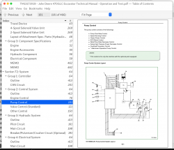
John Deere Excavator 470GLC Service Operation and Test Manual (TM13173X19)
Complete Diagnostics, Operation and Test manual for John Deere Excavator 470GLC (PIN: 1FF470GX__C047001-), with all the shop information to maintain, diagnose, and rebuild like professional mechanics.
John Deere Excavator 470GLC workshop Operation and Test manual includes:
* Numbered table of contents easy to use so that you can find the information you need fast.
* Detailed sub-steps expand on repair procedure information
* Numbered instructions guide you through every repair procedure step by step.
* Troubleshooting and electrical service procedures are combined with detailed wiring diagrams for ease of use.
* Notes, cautions and warnings throughout each chapter pinpoint critical information.
* Bold figure number help you quickly match illustrations with instructions.
* Detailed illustrations, drawings and photos guide you through every procedure.
* Enlarged inset helps you identify and examine parts in detail.
TM13173X19 - John Deere 470GLC Excavator Operational Principle Technical Manual (PIN: 1FF470GX_ _C047001— ) (Operation and Test).pdf
tm13173x54 - John Deere Escavadeira 470GLC (PIN: 1FF470GX_ _C047001— ).pdf
tm13173x63 - John Deere Excavadora 470GLC (PIN: 1FF470GX_ _C047001— ) Principios de funcionamiento.pdf
PRODUCT DETAILS:
Total Pages: 462 pages
File Format: PDF/EPUB/MOBI/AZW (PC/Mac/Android/Kindle/iPhone/iPad; bookmarked, ToC, Searchable, Printable)
Language: English Portuguese Spanish
Models: John Deere - 470GLC Excavator - 1FF470GX__C047001
MAIN SECTIONS
To The Reader
Additional References
Manual Composition
Page Number
Safety Alert Symbol and Headline Notations
Units Used
Symbol and Abbreviation
Safety
Safety
Operational Performance Test
Introduction
Standard
Engine Test
Machine Performance Test
Component Test
Adjustment
Troubleshooting
Diagnosing Procedure
Monitor
e-Service
Component Layout
Troubleshooting A
Troubleshooting B
Air Conditioner
Travel Device
Signal Control Valve
Others (Upperstructure)
Others (Undercarriage)
TABLE OF CONTENTS................1
Section T1: General................14
Group 1: Specifications................17
Specifications................17
Working Ranges................19
Group 2: Component Layout................14
Main Component................24
Electrical System (Overview)................27
Electrical System (Rear Tray)................28
Electrical System (Switch Panel)................30
Electrical System (Cab Behind Side)................32
Isolation Switch (Optional)................34
Engine................52
Pump Device................37
Control Valve................38
Check Valve / Accumulator................447
Signal Control Valve................40
Swing Device................42
Travel Device................43
4-Spool Solenoid Valve Unit................269
2-Spool Solenoid Valve Unit................269
Layout of Attachment Spec. Parts (Hydraulic System)................46
Group 3: Component Specifications................17
Engine................52
Engine Accessories................55
Hydraulic Component................56
Electrical Component................59
MEMO................462
MEMO................462
Section T2: System................64
Group 1: Controller................64
Outline................413
CAN Circuit................201
Group 2: Control System................64
Outline................413
Engine Control................76
Pump Control................101
Valve Control (Standard)................121
Other Control................150
Group 3: Hydraulic System................64
Outline................413
Pilot Circuit................161
Main Circuit................198
Breaker/Pulverizer/Crusher Circuit (Optional)................191
Group 4: Electrical System................64
Outline................413
Main Circuit................198
Electric Power Circuit (Key Switch: OFF)................199
CAN Circuit................201
Accessory Circuit................226
Preheating Circuit (Key Switch: ON, START)................205
Starting Circuit (Key Switch: START)................207
Charging Circuit (Key Switch: ON)................210
Surge Voltage Prevention Circuit................213
Pilot Shut-Off Circuit (Key switch: ON)................215
Engine Stop Circuit................217
Monitor Circuit................219
Security Circuit................220
Radio Circuit................222
Air Conditioner Circuit................224
Accessory Circuit................226
Work Light Circuit................227
Wiper/Washer Circuit................229
Cab Light Circuit................232
MEMO................462
MEMO................462
Section T3: Component Operation................238
Group 1: Pump Device................37
Outline................413
Main Pump................244
Regulators................246
Pilot Pump................257
N Sensor (Engine Speed Sensor)................258
Pump Delivery Pressure Sensor................259
Pump Displacement Angle Sensor................260
Group 2: Swing Device................42
Outline................413
Swing Reduction Gear................263
Swing Motor................265
Swing Parking Brake................401
Valve Unit................269
Group 3: Control Valve................38
Outline................413
Hydraulic Circuit................322
Flow Combiner Valve................327
Main Relief Valve................330
Overload Relief Valve (with Make-Up Function)................332
Boom Overload Relief Valve (Low Pressure)................336
Regenerative Valve................338
Anti-Drift Valve................343
Flow Rate Control Valve................347
Boom Lower Meter-In Cut Valve................354
Bypass Shut-Out Valve................357
Auxiliary Flow Combiner Valve................360
Group 4: Pilot Valve................238
Outline................413
Operation (Front Attachment / Swing and Travel Pilot Valves)................371
Operation (Auxiliary / Counterweight Removal and Installation Pilot Valve)................386
Shockless Function (Only for Travel Pilot Valve)................391
Group 5: Travel Device................43
Outline................413
Travel Reduction Gear................397
Travel Motor................399
Parking Brake................401
Travel Brake Valve................403
Overload Relief Valve................407
Travel Mode Control................409
Group 6: Signal Control Valve................40
Outline................413
Pilot Port................414
Shuttle Valve................417
Shockless Valve................445
Pump 1 Flow Rate Control Valve, Pump 2 Flow Rate Control Valve................425
Arm Flow Rate Control Valve Control Spool, Flow Combiner Valve Control Spool, Swing Parking Brake Release Spool................427
Group 7: Others (Upperstructure)................239
Pilot Shut-Off Solenoid Valve................437
Solenoid Valve................437
Fan Motor................440
Fan Valve................441
Pilot Relief Valve................444
Shockless Valve................445
Accumulator................447
Distribution Valve................448
Group 8: Others (Undercarriage)................239
Swing Bearing................456
Center Joint................457
Track Adjuster................458
MEMO................462
MEMO................462
Technical Information Feedback Form................464
John Deere Excavator 470GLC Service Operation and Test Manual (TM13173X19)


