
John Deere Wheeled Excavator 190DW Operation & Test Technical Service Manual (TM10542)
Complete Technical Diagnostics, Operation and Test Manual with electrical wiring diagrams for John Deere 190DW, with all the technical information to maintain, diagnose, rebuild like professional mechanics.
John Deere 190DW Wheeled Excavator workshop Operation and Test manual includes:
* Numbered table of contents easy to use so that you can find the information you need fast.
* Detailed sub-steps expand on repair procedure information
* Numbered instructions guide you through every repair procedure step by step.
* Troubleshooting and electrical service procedures are combined with detailed wiring diagrams for ease of use.
* Notes, cautions and warnings throughout each chapter pinpoint critical information.
* Bold figure number help you quickly match illustrations with instructions.
* Detailed illustrations, drawings and photos guide you through every procedure.
* Enlarged inset helps you identify and examine parts in detail.
TM10542 - John Deere 190DW Wheeled Excavator Technical Manual - Operation and Test.pdf|
PRODUCT DETAILS:
Total Pages: 1,833 pages
File Format: PDF (bookmarked, ToC, Searchable, Printable, high quality)
Language: English
MAIN SECTIONS
Foreword
Technical Information Feedback Form
General Information
Safety
Diagnostic Trouble Codes (DTC)
Main Controller (MCF) Diagnostic Trouble Codes
Engine Control Module (ECM) Diagnostic Trouble Codes
Information Controller (ICF) Diagnostic Trouble Codes
Air Conditioner Controller (ACF) Diagnostic Trouble Codes
Monitor Controller (MON) Diagnostic Trouble Codes
Option Controller (URF) Diagnostic Trouble Codes
Steering Column Monitor (SCM) Diagnostic Trouble Codes
Operational Checkout Procedure
Operational Checkout Procedure
Engine
Theory of Operation
Diagnostic Information
Tests
Electrical System
System Information
System Diagrams
Sub-System Diagnostics
Monitor Operation
References
Power Train
Theory of Operation
Diagnostic Information
Tests and Adjustments
Hydraulic System
Theory of Operation
Diagnostic Information
Tests
Heating and Air Conditioning
Theory of Operation
Diagnostic Information
Tests
Reference Material
Terminology Cross Reference Chart
Dealer Fabricated Tools
TABLE OF CONTENTS....1
Section 9000: General Information....23
Group 01: Safety....23
Recognize Safety Information....26
Follow Safety Instructions....27
Operate Only If Qualified....28
Wear Protective Equipment....29
Avoid Unauthorized Machine Modifications....30
Add Cab Guarding for Special Uses....31
Inspect Machine....32
Stay Clear of Moving Parts....33
Avoid High-Pressure Fluids....34
Avoid High-Pressure Oils....35
Beware of Exhaust Fumes....36
Prevent Fires....37
Prevent Battery Explosions....38
Handle Chemical Products Safely....39
Dispose of Waste Properly....40
Prepare for Emergencies....41
Use Steps and Handholds Correctly....42
Start Only From Operator's Seat....43
Use and Maintain Seat Belt....44
Prevent Unintended Machine Movement....45
Avoid Work Site Hazards....46
Keep Riders Off Machine....48
Avoid Backover Accidents....49
Avoid Machine Tip Over....50
Use Special Care When Lifting Objects....51
Add and Operate Attachments Safely....52
Park and Prepare for Service Safely....53
Service Cooling System Safely....54
Remove Paint Before Welding or Heating....55
Service Tires Safely....56
Make Welding Repairs Safely....57
Drive Metal Pins Safely....58
Section 9001: Diagnostic Trouble Codes (DTC)....59
Group 10: Main Controller (MCF) Diagnostic Trouble Codes....68
Main Controller (MCF) Diagnostic Trouble Codes....68
11000.02 - Abnormal EEPROM....59
11001.02 - Abnormal RAM....59
11002.02 - Abnormal A-D Conversion....59
11003.02 - Abnormal Sensor Voltage....59
11004.02 - Abnormal CAN Communication....59
11100.02 - Abnormal Engine Speed....59
11101.03 - Engine Control Dial Sensor Voltage High....59
11101.04 - Engine Control Dial Sensor Voltage Low....59
11200.03 - Pump 1 Delivery Pressure Sensor Voltage High....59
11200.04 - Pump 1 Delivery Pressure Sensor Voltage Low....59
11202.03 - Pump 2 Delivery Pressure Sensor Voltage High....59
11202.04 - Pump 2 Delivery Pressure Sensor Voltage Low....59
11203.03 - Steering Pump Delivery Pressure Sensor Voltage High....59
11203.04 - Steering Pump Delivery Pressure Sensor Voltage Low....59
11206.03 - Pump 1 Control Pressure Sensor Voltage High....59
11206.04 - Pump 1 Control Pressure Sensor Voltage Low....59
11208.03 - Pump 2 Control Pressure Sensor Voltage High....59
11208.04 - Pump 2 Control Pressure Sensor Voltage Low....59
11301.03 - Swing Pilot Pressure Sensor Voltage High....59
11301.04 - Swing Pilot Pressure Sensor Voltage Low....59
11302.03 - Boom-up Pilot Pressure Sensor Voltage High....59
11302.04 - Boom-up Pilot Pressure Sensor Voltage Low....59
11303.03 - Arm-in Pilot Pressure Sensor Voltage High....59
11303.04 - Arm-in Pilot Pressure Sensor Voltage Low....59
11305.03 - Travel Forward Pressure Sensor Voltage High....59
11305.04 - Travel Forward Pressure Sensor Voltage Low....59
11306.03 - Travel Reverse Pressure Sensor Voltage High....59
11306.04 - Travel Reverse Pressure Sensor Voltage Low....59
11307.03 - Front Attachment Pressure Sensor Voltage High....59
11307.04 - Front Attachment Pressure Sensor Voltage Low....59
11310.03 - Brake Pressure Sensor Voltage High....60
11310.04 - Brake Pressure Sensor Voltage Low....60
11311.03 - Brake Remaining Pressure Sensor Voltage High....60
11311.04 - Brake Remaining Pressure Sensor Voltage Low....60
11400.02 - Pump 2 Flow Rate Limit Solenoid Feedback Current Abnormal....60
11400.03 - Pump 2 Flow Rate Limit Solenoid Feedback Current High....60
11400.04 - Pump 2 Flow Rate Limit Solenoid Feedback Current Low....60
11401.02 - Torque Control Solenoid Feedback Current Abnormal....60
11401.03 - Torque Control Solenoid Feedback Current High....60
11401.04 - Torque Control Solenoid Feedback Current Low....60
11403.02 - Arm Regenerative Solenoid (SC) Feedback Current Abnormal....60
11403.03 - Arm Regenerative Solenoid (SC) Feedback Current High....60
11403.04 - Arm Regenerative Solenoid (SC) Feedback Current Low....60
11404.02 - Power Dig Solenoid (SG) Feedback Current Abnormal....60
11404.03 - Power Dig Solenoid (SG) Feedback Current High....60
11404.04 - Power Dig Solenoid (SG) Feedback Current Low....60
11410.02 - Pump 1 Flow Rate Limit Solenoid Feedback Current Abnormal....60
11410.03 - Pump 1 Flow Rate Limit Solenoid Feedback Current High....60
11410.04 - Pump 1 Flow Rate Limit Solenoid Feedback Current Low....60
11422.02 - Travel Speed Solenoid Feedback Current Abnormal....60
11422.03 - Travel Speed Solenoid Feedback Current High....60
11422.04 - Travel Speed Solenoid Feedback Current Low....60
11423.02 - Travel Make-up Solenoid Feedback Current Abnormal....60
11423.03 - Travel Make-up Solenoid Feedback Current High....60
11423.04 - Travel Make-up Solenoid Feedback Current Low....60
11424.02 - Axle Lock Solenoid (SI) Feedback Current Abnormal....60
11424.03 - Axle Lock Solenoid (SI) Feedback Current High....60
11424.04 - Axle Lock Solenoid (SI) Feedback Current Low....60
11425.02 - Work Brake Solenoid (SF) Feedback Current Abnormal....60
11425.03 - Work Brake Solenoid (SF) Feedback Current High....60
11425.04 - Work Brake Solenoid (SF) Feedback Current Low....60
11502.02 - Travel Motor Overspeed....60
11901.03 - Hydraulic Oil Temperature Sensor Voltage High....60
11901.04 - Hydraulic Oil Temperature Sensor Voltage Low....61
11910.02 - Engine Speed CAN Message Abnormal....61
11911.02 - Security Signal CAN Message Abnormal....61
11914.02 - Engine Coolant Temperature CAN Message Abnormal....61
11915.02 - Pilot Shutoff Signal CAN Message Abnormal....61
11918.02 - Work Mode CAN Message Abnormal....61
11920.02 - Fuel Flow Rate CAN Message Abnormal....61
11921.02 - Incorrect Odometer Value....61
Group 20: Engine Control Module (ECM) Diagnostic Trouble Codes....319
Engine Control Module (ECM) Diagnostic Trouble Codes....319
100.03 - Engine Oil Pressure Sensor Voltage Low (P0522)....61
100.04 - Engine Oil Pressure Sensor Voltage High (P0523)....61
102.03 - Boost Pressure Sensor Voltage Low (P0237)....61
102.04 - Boost Pressure Sensor Voltage High (P0238)....61
105.03 - Boost Temperature Sensor Voltage High (P1113)....61
105.04 - Boost Temperature Sensor Voltage Low (P1112)....61
108.03 - Barometric Pressure Sensor Voltage Low (P0107)....61
108.04 - Barometric Pressure Sensor Voltage High (P0108)....61
110.00 - Engine Coolant Temperature Hight (P1173)....61
110.03 - Engine Coolant Temperature Sensor Voltage High (P0118)....61
110.04 - Engine Coolant Temperature Sensor Voltage Low (P0117)....61
157.00 - Fuel Rail Pressure Abnormal (First Stage) (P0088)....61
157.00 - Fuel Rail Pressure Abnormal (Second Stage) (P0088)....61
157.02 - Fuel Rail Pressure High (Pump Over-Pressure) (P0089)....61
157.03 - Fuel Rail Pressure Sensor Voltage High (P0193)....61
157.04 - Fuel Rail Pressure Sensor Voltage Low (P0192)....61
172.03 - Intake Air Temperature Sensor Voltage High (P0113)....61
172.04 - Intake Air Temperature Sensor Voltage Low (P0112)....61
174.03 - Fuel Temperature Sensor Voltage High (P0183)....61
174.04 - Fuel Temperature Sensor Voltage Low (P0182)....61
190.00 - Engine Overspeed (P0219)....61
628.02 - Abnormal ROM (P1603)....61
633.07 - Pressure Limiter Open (P1095)....61
636.02 - Abnormal Cam Angle Sensor (No Signal) (P0340)....62
636.02 - Abnormal Cam Angle Sensor (Abnormal Signal) (P0341)....62
636.07 - Phase Mismatch of Cam Angle Sensor (P1345)....62
639.02 - CAN Communication Error (U2104)....62
639.03 - CAN Time Out (U2106)....62
651.03 - Injector 1 Drive System Open Circuit (P0201)....62
652.03 - Injector 2 Drive System Open Circuit (P0202)....62
653.03 - Injector 3 Drive System Open Circuit (P0203)....62
654.03 - Injector 4 Drive System Open Circuit (P0204)....62
723.02 - Abnormal Crank Speed Sensor (No Signal) (P0335)....62
723.02 - Abnormal Crank Speed Sensor (Abnormal Signal) (P0336)....62
987.03 - Abnormal Check Engine Lamp (P0650)....62
1077.02 - Abnormal IC for CPU Watching (P0601)....62
1079.02 - 5 Volt Power Source 1 Voltage Abnormal (P1632)....62
1080.02 - 5 Volt Power Source 2 Voltage Abnormal (P1633)....62
1239.01 - No Pressure To Pump (P0087)....62
1240.01 - No Pressure To Pump (P1093)....62
1347.00 - Suction Control Valve Drive Circuit Open or Shorted (P0090)....62
1381.03 - High Voltage Fault of Fuel Differential Pressure Sensor....62
1381.04 - Low Voltage Fault of Fuel Differential Pressure Sensor....62
1485.02 - Engine Control Module (ECM) Relay Abnormal (P1625)....62
10001.03 - Abnormal EGR Position (P0487)....62
10002.02 - Abnormal EGR Valve Control (P0488)....62
10003.02 - Injector Drive System Common 1 Abnormal (P1262)....62
10004.02 - Injector Drive System Common 2 Abnormal (P1262)....62
10005.01 - Charge Circuit Abnormal Bank 1 (P0611)....62
10006.1 - Charge Circuit Abnormal Bank 2 (P0612)....62
10007.02 - Abnormal CPU (P0606)....62
10008.02 - Abnormal A-D Conversion (P1630)....62
10009.02 - 5 Volt Power Source 3 Voltage Abnormal (P1634)....62
10010.02 - 5 Volt Power Source 4 Voltage Abnormal (P1635)....62
10011.02 - 5 Volt Power Source 5 Voltage Abnormal (P1261)....62
10013.02 - Abnormal EEPROM (P1631)....62
Group 30: Information Controller (ICF) Diagnostic Trouble Codes....377
Information Controller (ICF) Diagnostic Trouble Codes....377
14000.02 - Abnormal CAN Communication....63
14001.02 - Flash Memory: Read - Write Error....63
14002.02 - External RAM: Read - Write Error....63
14003.02 - EEPROM: Sum Check Error....63
14006.02 - Satellite Communication Terminal: Communication Error....63
14008.02 - Abnormal Internal RAM....63
14100.02 - Satellite Communication Terminal: Abnormal EEPROM....63
14101.02 - Satellite Communication Terminal: Abnormal IB-OB Queue....63
14102.02 - Satellite Communication Terminal: Abnormal Local Loop Back....63
14103.02 - Satellite Communication Terminal: Satellite Cannot Be Found....63
14104.02 - Satellite Communication Terminal: Remote Loop Back Failure 1....63
14105.02 - Satellite Communication Terminal: Remote Loop Back Failure 2....63
14106.02 - Satellite Communication Terminal: Received Data is Not Same With Sent Data....63
Group 40: Air Conditioner Controller (ACF) Diagnostic Trouble Codes....417
Air Conditioner Controller (ACF) Diagnostic Trouble Codes....417
21 - Mix Door Open Circuit....63
Section 9005: Operational Checkout Procedure....771
Group 10: Operational Checkout Procedure....771
Operational Checkout....835
Section 9010: Engine....898
Group 05: Theory of Operation....898
Engine Component Location....901
Engine Fuel System Operation....902
Cooling System Operation....908
Engine Lubrication System Operation....910
Engine Intake and Exhaust System Operation....912
Engine Turbocharger Operation....913
Exhaust Gas Recirculation (EGR) Operation....914
Quick On System Operation....916
Engine Speed Control System Operation....917
Group 15: Diagnostic Information....898
4HK1 Isuzu Diesel Engine....924
Diagnose Engine Malfunctions....925
Engine Cranks But Will Not Start....898
Engine Misfires Or Runs Irregularly....898
Engine Does Not Develop Full Power....898
Engine Overheats....898
Auto-Idle Does Not Work....898
Coolant Temperature Too Low....898
Coolant in Oil or Oil in Coolant....898
Low Engine Oil Pressure....898
High Engine Oil Pressure....898
Engine Uses Too Much Oil....898
Engine Uses Too Much Fuel....898
Engine Emits Excessive Black or Gray Exhaust Smoke....898
Engine Emits Excessive White Exhaust Smoke....898
Turbocharger Excessively Noisy or Vibrates....898
Oil Dripping From Turbocharger Adapter....898
Excessive Drag in Turbocharger Rotating Members....898
Fuel In Oil....898
Engine Speed Can Not Be Controlled With Travel Pedal (Travel Pedal Engine Speed Control)....898
Group 25: Tests....899
Serpentine Belt Check and Adjust....976
High Pressure Fuel Pump Timing Check....978
Engine Valve Lash (Clearance) Check and Adjust....980
Engine Compression Pressure Test....984
Air Filter Restriction Indicator Switch Test....986
Engine Power Test Using Turbocharger Boost Pressure....988
Engine Oil Pressure Test....992
Section 9015: Electrical System....994
Group 05: System Information....994
Electrical Diagram Information....1005
Group 10: System Diagrams....994
Explanation of Wire Markings....1012
Fuse and Relay Specifications....1013
System Functional Schematic, Component Location, and Wiring Diagram Master Legend....1016
System Functional Schematic....1026
Cab Harness (W1) Component Location....1038
Cab Harness (W1) Wiring Diagram....1043
Machine Harness (W2) Component Location....1050
Machine Harness (W2) Wiring Diagram....1052
Monitor Harness (W3) Component Location....1056
Monitor Harness (W3) Wiring Diagram....1058
Engine Harness (W4) Component Location....1059
Engine Harness (W4) Wiring Diagram....1060
Floor Harness (W5) Component Location....1061
Floor Harness (W5) Wiring Diagram....1063
Chassis Harness (W6) Component Location....1064
Chassis Harness (W6) Wiring Diagram....1066
Right Console Harness (W7) Component Location....1068
Right Console Harness (W7) Wiring Diagram....1070
Pump Harness (W8) Component Location....1071
Pump Harness (W8) Wiring Diagram....1073
Left Console Harness (W9) Component Location....1074
Left Console Harness (W9) Wiring Diagram....1075
Air Suspension Seat Harness (W10) Component Location....1077
Air Suspension Seat Harness (W10) Wiring Diagram....1079
Right Pilot Control Lever Harness (W11) Component Location....1080
Right Pilot Control Lever Harness (W11) Wiring Diagram....1081
Swing Park Brake Solenoid Harness (W12) Component Location....1082
Swing Park Brake Solenoid Harness (W12) Wiring Diagram....1084
Blade and/or Outrigger Control Lever Harness (W13) Component Location....1085
Blade and/or Outrigger Control Lever Harness (W13) Wiring Diagram....1086
Boom Positioning and/or Assist Pressure Sensor Harness (W14) Component Location....1087
Boom Positioning and/or Assist Pressure Sensor Harness (W14) Wiring Diagram....1088
Digital Assist Harness (W17) Component Location—If Equipped....1089
Digital Assist Harness (W17) Wiring Diagram—If Equipped....1090
Digital or Analog Assist Solenoid Harness (W18) Component Location....1091
Digital or Analog Assist Solenoid Harness (W18) Wiring Diagram....1092
Cab Light Timer Harness (W19) Component Location....1093
Cab Light Timer Harness (W19) Wiring Diagram....1095
Boom Positioning and/or Auxiliary Select Harness (W20) Component Location....1096
Boom Positioning and/or Auxiliary Select Harness (W20) Wiring Diagram....1097
Seat Heater Switch Harness (W21) Component Location—If Equipped....1099
Seat Heater Switch Harness (W21) Wiring Diagram—If Equipped....1100
Left Pilot Control Lever Harness (W22) Component Location....1101
Left Pilot Control Lever Harness (W22) Wiring Diagram....1103
Travel Alarm Cancel Switch Harness (W24) Component Location....1104
Travel Alarm Cancel Switch Harness (W24) Wiring Diagram....1105
Travel Alarm Cancel Switch Sub Harness (W25) Component Location....1106
Travel Alarm Cancel Switch Sub Harness (W25) Wiring Diagram....1107
Travel Alarm Harness (W26) Component Location....1108
Travel Alarm Harness (W26) Wiring Diagram....1109
Attachment Harness (W27) Component Location—If Equipped....1110
Attachment Harness (W27) Wiring Diagram—If Equipped....1112
Auxiliary Solenoid Harness (W29) Component Location....1114
Auxiliary Solenoid Harness (W29) Wiring Diagram....1116
Positioning Harness (W30) Component Location....1117
Positioning Harness (W30) Wiring Diagram....1118
Rear Cab Light Relay Harness (W31) Component Location....1119
Rear Cab Light Relay Harness (W31) Wiring Diagram....1121
Rear Cab Light Harness (W32) Component Location....1122
Rear Cab Light Harness (W32) Wiring Diagram....1123
12-Volt Power Converter Harness (W33) Component Location....1124
12-Volt Power Converter Harness (W33) Wiring Diagram....1125
Beacon Harness (W34) Component Location....1126
Beacon Harness (W34) Wiring Diagram....1128
Beacon Relay Harness (W35) Component Location....1129
Beacon Relay Harness (W35) Wiring Diagram....1130
Beacon Switch Harness (W36) Component Location....1131
Beacon Switch Harness (W36) Wiring Diagram....1132
Beacon Lamp Harness (W37) Component Location....1133
Beacon Lamp Harness (W37) Wiring Diagram....1134
Front Cab Light 1 Relay Harness (W38) Component Location....1135
Front Cab Light 1 Relay Harness (W38) Wiring Diagram....1137
Front Cab Light 2 Relay Harness (W40) Component Location....1138
Front Cab Light 2 Relay Harness (W40) Wiring Diagram....1139
Front Cab Light 2 Harness (W41) Component Location....1140
Front Cab Light 2 Harness (W41) Wiring Diagram....1141
Pilot Shutoff Switch Harness (W42) Component Location....1142
Pilot Shutoff Switch Harness (W42) Wiring Diagram....1143
Service Advisor Connector Harness (W43) Component Location....1145
Service Advisor Connector Harness (W43) Wiring Diagram....1148
Front Cab Light Harness (W44) Component Location....1150
Front Cab Light Harness (W44) Wiring Diagram....1151
JDLink™ System Harnesses Component Location—MIG/GTT....1152
JDLink™ System Harnesses Component Location—MTG/SAT....1154
JDLink™ System Wiring Diagrams—MIG/GTT....1156
JDLink™ System Wiring Diagrams—MTG/SAT....1161
Group 15: Sub-System Diagnostics....996
Controller Area Network (CAN) Theory of Operation....1164
Starting and Charging Circuit Theory of Operation....1166
Monitor Controller Circuit Theory of Operation....1169
Engine Control Module (ECM) Circuit Theory of Operation....1175
Main Controller (MCF) Circuit Theory of Operation....1180
Information Controller (ICF) Circuit Theory of Operation....1190
Option Controller (URF) Circuit Theory of Operation....1192
Steering Column Monitor (SCM) Circuit Theory of Operation....1198
Travel Alarm Circuit Theory of Operation....1201
Windshield Wiper and Washer Circuit Theory of Operation....1203
Pilot Shutoff Circuit Theory of Operation....1205
Attachment Control Circuit Theory of Operation....1207
Lights Circuit Theory of Operation....1214
Blade and/or Outrigger Control Circuit Theory of Operation....1218
JDLink™ Circuit Theory of Operation—If Equipped....1222
Group 16: Monitor Operation....997
Monitor Menu Operation....1226
Monitor Service Menu Operation....1227
Group 20: References....997
Monitor Data Items....1233
Reading Diagnostic Trouble Codes with Monitor Display....1235
Service ADVISOR™ Diagnostic Application....1237
Service ADVISOR™ Connection Procedure....1238
Reading Diagnostic Trouble Codes with Service ADVISOR™ Diagnostic Application....1240
Service ADVISOR™ Interactive Tests....1243
JDLink™ System Identification....1244
JDLink™ Connection Procedure—If Equipped....1247
Information Controller (ICF) Recorded Data....1248
Fuse Test....1251
Relay Test....1257
Pressure Sensor Test....1258
Solenoid Test....1261
Proportional Solenoid Test....1262
Temperature Sensor Test....1263
Alternator Test....1264
Electrical Component Checks....1266
Battery Remove and Install....1272
Rear Cover Remove and Install....1275
Main Controller (MCF) Remove and Install....1277
Engine Control Module (ECM) Remove and Install....1279
Information Controller (ICF) Remove and Install....1281
Option Controller (URF) Remove and Install....1282
Steering Column Monitor (SCM) Remove and Install....1283
Monitor Controller Remove and Install....1285
Key Switch Remove and Install....1288
Switch Panel Remove and Install....1289
Travel Alarm Remove and Install....1291
Left Console Switch Remove and Install....1292
Disconnect Tab Retainer Connectors....1293
Disconnecting Spring Wire Clip Connectors....1294
Replace DEUTSCH DEUTSCH is a trademark of the Deutsch Co. Connectors....998
Replace DEUTSCH DEUTSCH is a trademark of Deutsch Co. Rectangular or Triangular Connectors....998
Install DEUTSCH DEUTSCH is a trademark of the Deutsch Co. Contact....998
Replace WEATHER PACK WEATHER PACK is a trademark of Packard Electric. Connector....998
Install WEATHER PACK WEATHER PACK is a trademark of Packard Electric. Contact....998
Replace (Pull Type) Metri-Pack™ Connectors....1305
Replace (Push Type) Metri-Pack™ Connectors....1307
Replace CINCH CINCH is a trademark of the Cinch Co. Connectors....998
Install CINCH CINCH is a trademark of the Cinch Co. Contact....998
Repair 32 and 48 Way CINCH CINCH is a trademark of the Cinch Co. Connectors....998
Remove Connector Body from Blade Terminals....1316
Section 9020: Power Train....1317
Group 05: Theory of Operation....1317
Travel Hydraulic System Diagram and Operation....1482
Brake System Diagram and Operation....1323
Travel Pilot Control Valve Operation....1542
Travel Shockless Valve Operation....1327
Travel Motor and Regulator Operation....1328
Counterbalance Valve Operation....1340
Transmission Operation....1344
Shift Interlock Operation....1350
Transmission Disconnect Operation....1351
Transmission Control Valve....1353
Park Brake Operation....1358
Service Brake Circuit Operation....1360
Brake Accumulator Charging Valve Operation....1366
Axle Lock Circuit Operation....1369
Group 15: Diagnostic Information....1317
Diagnose Transmission Malfunctions....1317
Diagnose Brake Malfunctions....1317
Travel Hydraulic System Schematic....1692
Travel Hydraulic System Component Location....1703
Travel Hydraulic System Line Identification....1436
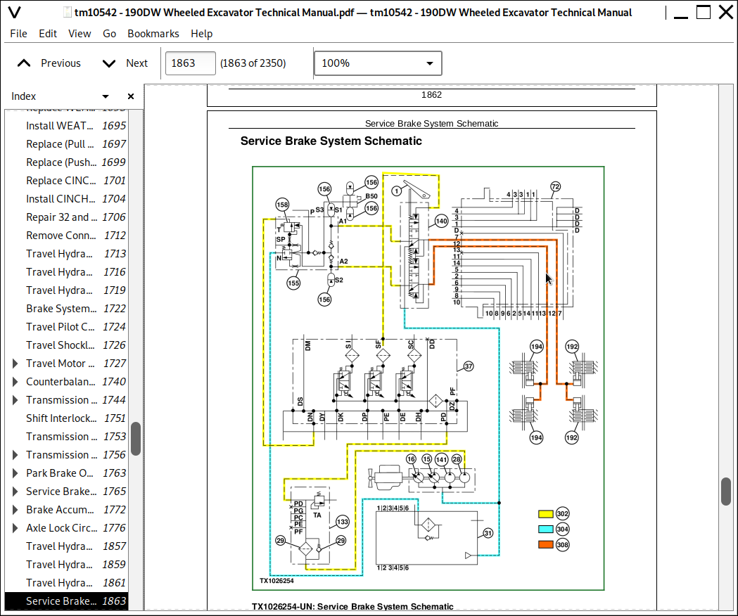
Service Brake System Schematic....1437
Service Brake System Component Location....1439
Service Brake System Line Identification....1441
Axle Lock System Line Identification....1442
Axle Lock System Schematic....1444
Axle Lock System Component Location....1445
Group 20: Tests and Adjustments....1317
Transmission Manual Disconnection Procedure....1449
Brake Bleeding Procedure....1451
Brake Warning Set Pressure (Decrease)....1453
Brake Warning Set Pressure (Increase)....1459
Brake Warning Set Pressure (Increase)....1459
Rear Brake Pressure Test....1462
Front Brake Pressure Test....1465
Transmission Control Valve Pressure Test....1468
Brake Accumulator Pressure Test....1471
Measure Swing Bearing Wear....1474
Section 9025: Hydraulic System....1477
Group 05: Theory of Operation....1477
Hydraulic System Diagram and Operation....1482
Pilot System Diagram and Operation....1484
Steering System Diagram and Operation....1494
Blade and/or Outrigger System Diagram and Operation....1496
Hydraulic Assist Diagram and Operation....1498
Two Piece Boom Positioning Diagram and Operation....1501
Pilot Pump, Pressure Regulating Valve and Filter Operation....1505
Pilot Shutoff Solenoid Valve Operation....1507
Pilot Control Valve Operation....1542
Travel Pilot Control Valve Operation....1542
Pilot Operation of Control Valve Operation....1542
Pilot Signal Manifold Operation....1519
Pump 1, Pump 2 and Drive Gearbox Operation....1529
Pump 1 and Pump 2 Regulator Operation....1532
Engine Speed Sensing Control Circuit Operation....1540
Control Valve Operation....1542
Control Valve Check Valves Identification and Operation....1554
Main Relief Valve Circuit Operation....1558
Circuit Relief and Anticavitation Valve Operation....1560
Auxiliary Flow Combiner Valve Operation....1562
Boom Regenerative Valve Circuit Operation....1567
Arm Regenerative Valve Circuit Operation....1570
Bucket Regenerative Valve Circuit Operation....1573
Boom and Arm Reduced Leakage Valves Operation....1576
Bucket Flow Rate Control Valve Circuit Operation....1580
Auxiliary Flow Rate Control Valve Circuit Operation....1583
Swing Reduction Gearbox Operation....1584
Swing Motor, Crossover Relief Valve, and Make-Up Check Valve Operation....1585
Swing Motor Dampener Valve....1589
Swing Motor Park Brake Release Circuit Operation....1599
Swing Shockless Valve Operation....1600
Center Joint Operation....1602
Steering Valve Operation....1604
Blade and/or Outrigger Check Valve Operation....1610
Cylinder Holding Valve Operation....1612
Cylinder Operation....1616
Return Filter Operation....1618
Group 15: Diagnostic Information....1478
Diagnose Hydraulic System Malfunctions....1478
Diagnose Pilot Circuit Malfunctions....1478
Diagnose Dig Circuit Malfunctions....1478
Diagnose Swing Circuit Malfunctions....1478
Diagnose Steering Circuit Malfunctions....1478
Diagnose Blade and/or Outrigger Circuit Malfunctions....1478
Pump 1, Pump 2, and Pilot Pump Line Identification....1682
Control Valve Line Identification....1683
Swing Motor Line Identification....1686
Pilot Control Valve-to-Pilot Signal Manifold Component Location—Excavator Pattern....1687
Pilot Signal Manifold-to-Control Valve Line Connection....1688
Steering System Component Location....1689
Steering System Line Connection....1690
Hydraulic System Schematic....1692
Hydraulic System Component Location....1703
Hydraulic System Line Connections....1706
Group 25: Tests....1478
JT05800 Digital Thermometer Installation....1708
JT02156A Digital Pressure/Temperature Analyzer Installation....1709
Hydraulic Oil Cleanup Procedure Using Portable Filter Caddy....1710
Hydraulic Oil Warm-Up Procedure....1711
Pilot Pressure Regulating Valve Test and Adjustment....1714
Control Valve Spool Actuating Pilot Pressure Test....1718
Arm Regenerative Solenoid Valve Test and Adjustment....1722
Torque Control Solenoid Valve Test and Adjustment....1727
Axle Lock Solenoid Valve Test and Adjustment....1731
Work Brake Solenoid Valve Test and Adjustment....1736
Pump Control Pilot Pressure Signal Test....1741
Main Relief Valve Test and Adjustment....1744
Circuit Relief Valve Test and Adjustment....1749
Swing Motor Crossover Relief Valve Test and Adjustment....1757
Steering Relief Valve Pressure Test....1762
Two Piece Boom Positioning and Hydraulic Assist Relief Valve Test and Adjustment....1765
Pump Flow Test....1770
Swing Motor Leakage Test....1779
Steering System Leakage Test....1782
Steering Cylinder Leakage Test....1784
Cylinder Drift Test—Boom, Arm, and Bucket....1786
Section 9031: Heating and Air Conditioning....1788
Group 05: Theory of Operation....1788
Air Conditioning System Cycle of Operation....1791
Group 15: Diagnostic Information....1788
Diagnose Air Conditioning System Malfunctions....1796
Diagnose Heating System Malfunctions....1799
Heater and Air Conditioner Diagnostic Trouble Code Check....1801
Heater and Air Conditioner Component Location....1807
Group 25: Tests....1788
R134a Refrigerant Cautions and Proper Handling....1809
Heater and Air Conditioner Operational Checks....1810
R134a Air Conditioning System Test....1824
Air Conditioner Compressor Clutch Test....1817
Refrigerant Leak Test....1818
Refrigerant Hoses and Tubing Inspection....1819
Air Conditioner High/Low-Pressure Switch Test....1820
Air Conditioner Freeze Control Switch Test....1823
Air Conditioning System Test....1824
Air Conditioner Compressor Belt Check and Adjustment....1827
Operating Pressure Diagnostic Chart....1828
Section 9050: Reference Material....1830
Group 05: Terminology Cross Reference Chart....1833
Terminology Cross Reference Chart....1833
Section 9900: Dealer Fabricated Tools....1835
Group 99: Dealer Fabricated Tools....1835
DFT1218 Split Flange Hose Cap....1837
John Deere Wheeled Excavator 190DW Operation & Test Technical Service Manual (TM10542)
![]()