
John Deere 200LC, 330LC and 370 Excavator Logger Service Technical Manual Supplement (Repair) (TM1847)
Complete service repair manual Supplement for John Deere 200LC, 330LC and 370 Excavator Logger, with all the workshop information to maintain, repair, and rebuild like professional mechanics.
John Deere 200LC, 330LC and 370 Excavator Logger workshop service repair manual Supplement includes:
* Numbered table of contents easy to use so that you can find the information you need fast.
* Detailed sub-steps expand on repair procedure information
* Numbered instructions guide you through every repair procedure step by step.
* Troubleshooting and electrical service procedures are combined with detailed wiring diagrams for ease of use.
* Notes, cautions and warnings throughout each chapter pinpoint critical information.
* Bold figure number help you quickly match illustrations with instructions.
* Detailed illustrations, drawings and photos guide you through every procedure.
* Enlarged inset helps you identify and examine parts in detail.
TM1847 - John Deere 200LC, 330LC and 370 Excavator Logger Technical Manual Supplement - Repair.pdf
TM1847 - John Deere 200LC, 330LC and 370 Excavator Logger Technical Manual Supplement - Repair.epub
Total Pages: 491 pages
File Format: PDF (bookmarked, ToC, Searchable, Printable, high quality)
Language: English
MAIN SECTIONS
Foreword
Technical Information Feedback Form
General Information
Safety
General Specifications
Torque Values
Fuels and Lubricants
Tracks
Track System
Axles and Suspension Systems
Axle Shaft, Bearings, and Reduction Gears
Hydraulic System
Engine Auxiliary Systems
Cold Weather Starting Aids
Speed Controls
External Exhaust Systems
External Fuel Supply Systems
Electrical System
Batteries, Support, and Cables
Wiring Harness and Switches
System Controls
Frame or Supporting Structure
Frame Installation
Frame Bottom Guards
Chassis Weights
Operator's Station
Removal and Installation
Operator Enclosure
Steps and Handholds
Heating and Air Conditioning
Sheet Metal and Styling
Miscellaneous Shields
Safety and Convenience
Fire Extinguisher
Horn and Warning Devices
Pneumatic Systems
Removal and Installation
Excavator
Frames
Hydraulic System
Dealer Fabricated Tools
tm1847 - 200lc 330lc and 370 excavator logger repair supplement
Table of Contents
Foreword
Technical Information Feedback Form
Section 00: General Information
Group 0001: Safety
Follow Safe Procedures
Prepare for Emergencies
Handle Fluids Safely-Avoid Fires
Prevent Battery Explosions
Handle Chemical Products Safely
Prevent Acid Burns
Avoid High-Pressure Fluids
Warn Others of Service Work
Park Machine Safely
Support Machine Properly
Operate Only from Operator's Seat
Stay Clear of Moving Parts
Avoid Power Lines
Use Handholds and Steps
Keep Riders Off Machine
Move and Operate Machine Safely
Wear Protective Clothing
Protect Against Flying Debris
Protect Against Noise
Illuminate Work Area Safely
Service Machines Safely
Remove Paint Before Welding or Heating
Avoid Heating Near Pressurized Fluid Lines
Beware of Exhaust Fumes
Use Proper Lifting Equipment
Service Cooling System Safely
Dispose of Waste Properly
Work in a Clean Area
Use Tools Properly
Replace Safety Signs
Live With Safety
Group 0002: General Specifications
200LC Log Loader Live Heel Grapple With 2921 mm (9 Ft 7 in.) Track Gauge and Side Entry Cab With 1219 mm (48 in.) Riser-Specifications
330LC Log Loader Live Heel Grapple With 3100 mm (10 Ft 2 in.) Track Gauge, Rear Entry Cab With 1830 mm (72 in.) Riser, and Heavy Duty Belly Pan-Specifications
330LC Log Loader Live Heel Grapple With 2921 mm (9 Ft 7 in.) Track Gauge and Rear Entry Cab With 1219 mm (48 in.) Riser-Specifications
330LC Log Loader Live Heel Grapple With 2921 mm (9 Ft 7 in.) Track Gauge and Side Entry Cab With 1219 mm (48 in.) Riser-Specifications
330LC Road Builder With 2921 mm (9 Ft 7 in.) Track Gauge and Side Entry Cab-Specifications
200LC Log Loader Live Heel Grapple Working Ranges
330LC Log Loader Live Heel Grapple Working Ranges
200LC Excavator Logger Engine Specifications
200LC Excavator Logger Drain and Refill Capacities
330LC/370 Excavator Logger Engine Specifications
330LC/370 Drain and Refill Capacities
Lift Capacity-200LC Logger Live Heel Grapple With 2921 mm (9 Ft 7 in.) Track Gauge and Side Entry Cab With 1219 mm (48 in.) Riser
Lift Capacity-330LC Logger Live Heel Grapple With 2921 mm (9 Ft 7 in.) Track Gauge and Rear Entry Cab With 1219 mm (48 in.) Riser
Lift Capacity-330LC Logger Live Heel Grapple With 2921 mm (9 Ft 7 in.) Track Gauge and Side Entry Cab With 1219 mm (48 in.) Riser
Lift Capacity-330LC Logger Live Heel Grapple With 3100 mm (10 Ft 2 in.) Track Gauge and Rear Entry Cab With 1830 mm (72 in.) Riser
Lift Capacity-330LC Logger Butt-N-Top Grapple With 3100 mm (10 Ft 2 in.) Track Gauge and Rear Entry Cab With 1830 mm (72 in.) Riser
Lift Capacity-330LC Logger Road Builder With 2591 mm (8 Ft 6 in.) Track Gauge, 2.3 Cubic Yard Bucket, Hydraulic Thumb and Guarding Package
Lift Capacity-370 Logger Live Heel Grapple With 2921 mm (9 Ft 7 in.) Track Gauge and Rear Entry Cab With 1219 mm (48 in.) Riser
Lift Capacity-370 Logger Live Heel Grapple With 3100 mm (10 Ft 2 in.) Track Gauge and Rear Entry Cab With 1830 mm (72 in.) Riser
Lift Capacity-370 Logger Butt-N-Top Grapple With 3100 mm (10 Ft 2 in.) Track Gauge and Rear Entry Cab With 1830 mm (72 in.) Riser
Lift Capacity-370 Logger Road Builder With 2591 mm (8 Ft 6 in.) Track Gauge, 2.3 Cubic Yard Bucket, Hydraulic Thumb and Guarding Package
Group 0003: Torque Values
Unified Inch Bolt and Cap Screw Torque Values
Metric Bolt and Cap Screw Torque Values
Additional Metric Cap Screw Torque Values
Check Oil Lines and Fittings
Service Recommendations for O-Ring Boss Fittings
Service Recommendations for Flat Face O-Ring Seal Fittings
Service Recommendations for 37° Flare and 30° Cone Seat Connectors
Service Recommendations For Flared Connections-Straight or Tapered Threads
Service Recommendations For Inch Series Four Bolt Flange Fittings
Service Recommendations for Metric Series Four Bolt Flange Fitting
Group 0004: Fuels and Lubricants
Diesel Fuel
Lubricity Of Diesel Fuels
Low Sulfur Diesel Fuel Conditioner
Diesel Fuel Storage
Fuel Tank
Do Not Use Galvanized Containers
Diesel Engine and Pump Gearbox Oils
Hydraulic Oil
Swing Gearbox And Propel Gearbox Oils
Track Roller, Front Idler, and Carrier Roller Oil
Track Adjuster, Working Tool Pivot, Swing Bearing, and Swing Bearing Gear Grease
Oil Filters
Lubricant Storage
Alternative and Synthetic Lubricants
Mixing of Lubricants
Section 01: Tracks
Group 0130: Track System
Service Equipment and Tools
Other Material
Specifications
Remove and Install Rock Guards
Measure Track Roller Wear
Remove and Install Track Roller
Remove and Install Track Carrier Roller
Disassemble and Assemble Track Carrier Roller
Measure Track Chain Link Wear
Measure Track Chain Bushing Wear
Adjust Track Sag
Disassemble and Assemble Track Adjuster Cylinder-330LC
Section 02: Axles and Suspension Systems
Group 0250: Axle Shaft, Bearings, and Reduction Gears
Specifications
Remove and Install Propel Gearbox-330LC
Group 0260: Hydraulic System
Service Equipment and Tools
Specifications
Remove and Install Propel Motor and Park Brake-330LC
Section 05: Engine Auxiliary Systems
Group 0505: Cold Weather Starting Aids
Other Material
Remove and Install Cold Weather Start Aid
Group 0515: Speed Controls
Specifications
Engine Speed Learning Procedure-Rear Entry Cab Excavator Logger
Engine Speed Learning Procedure-Side Entry Cab Excavator Logger
Group 0530: External Exhaust Systems
Remove and Install Muffler
Group 0560: External Fuel Supply Systems
Other Material
Specifications
Remove and Install Fuel Tank (Standard With Counterweight Tank)-330LC/370
Remove and Install Fuel Tank (High Capacity)-330LC/370
Section 16: Electrical System
Group 1671: Batteries, Support, and Cables
Charge Battery (Rear Entry Cab)
Adding 12-Volt Accessories
Group 1674: Wiring Harness and Switches
Functional Schematic and Component Location Legend
Side Entry Cab Component Location Drawing
Rear Entry Cab Component Location Drawing
Frame Component Location Drawing (72” Rear Entry Cab Live Heel Grapple)
Frame Component Location Drawing (72” Rear Entry Cab Butt-N-Top Grapple)
Connecting Engine and Pump Controller (EPC) Harness Connector
Replacing Fuses-Rear Entry Cab
Replacing Fuses-Side Entry Cab With Riser
Remove and Install Forestry Cab Ground Straps
Remove and Install 24-Volt to 12-Volt Converter
Remove and Install Cab Tilt Switch
Group 1675: System Controls
Welding On Machine
Remove and Install Engine and Pump Controller (EPC) (Side Entry and Forestry Cab)
Remove and Install Engine and Pump Controller (EPC) (Rear Entry Cab)
Section 17: Frame or Supporting Structure
Group 1740: Frame Installation
Welding On Machine
Group 1746: Frame Bottom Guards
Specifications
Under Decking Covers
Swivel Guard
Extreme Duty Swivel Guard
Group 1749: Chassis Weights
Service Equipment and Tools
Specifications
Remove and Install Counterweight
Remove and Install Counterweight With Fuel Tank
Section 18: Operator's Station
Group 1800: Removal and Installation
Specifications
Remove and Install Cab
Group 1810: Operator Enclosure
Remove and Install Rear Entry Cab Windows
Remove and install Rear Entry Cab Right Side Window
Remove and Install Rear Entry Cab Door
Remove and Install Rear Entry Cab Window Guard
Remove and Install Forestry Cab Rear Window
Remove and Install Forestry Cab Windows
Remove and Install Forestry Cab Door Window
Remove and Install Forestry Cab Door
Remove and Install BC Road Builder Cab Window
Remove and Install BC Roadbuilder Cab Guard
Remove and Install BC Road Builder Cab Left Window Guard
Group 1822: Steps and Handholds
Specifications
Remove and Install High Capacity Fuel Tank (Option) Handhold
Remove and Install Step (72 Inch Rear Entry Cab)
Remove and Install Step (48 Inch Rear Entry Cab)
Remove and Install Grab Handle
Group 1830: Heating and Air Conditioning
Specifications
Heater and Air Conditioner (72 Inch Rear Entry Cab)
Remove and Install Air Conditioning Piping (Rear Entry Cab)
Remove and Install Receiver-Dryer (Side Entry Cab)
Remove and Install Receiver-Dryer (Rear Entry Cab)
Remove and Install Evaporator (Rear Entry Cab)
Remove and Install Heater Core and Blower Motor (Side Entry Cab)
Remove and Install Heater Core and Blower Motor (Rear Entry Cab)
Remove and Install Heater Hoses (Side Entry Cab)
Remove and Install Heater Hoses (Rear Entry Cab)
Section 19: Sheet Metal and Styling
Group 1913: Miscellaneous Shields
Remove and Install Log Deflector
Remove and Install Side Guarding 330LC and 370 Loggers
Remove and Install High Profile Side Guarding With Counterweight Fuel Tank-330LC/370
Remove and Install Side Guarding With High Capacity Fuel Tank-330LC/370
Remove and Install Side Guarding-200LC
Remove and Install Cylinder Mounted Arm Cylinder Guard
Remove and Install Boom Mounted Arm Cylinder Guard
Remove and Install Boom Mounted Cylinder Guard
Section 20: Safety and Convenience
Group 2003: Fire Extinguisher
Remove and Install Fire Extinguisher
Group 2004: Horn and Warning Devices
Remove and Install Air Horn
Section 22: Pneumatic Systems
Group 2200: Removal and Installation
Remove and Install Air Compressor
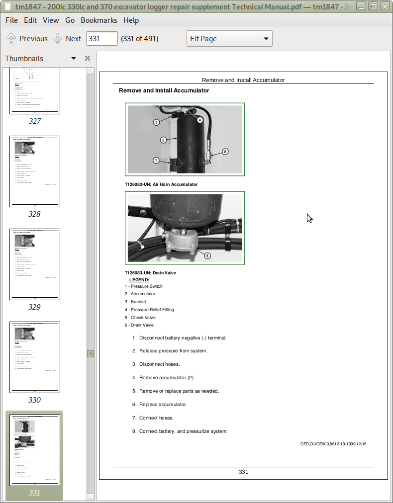
Remove and Install Accumulator
Remove and Install Check Valve
Remove and Install Pressure Switch
Remove and Install Drain Valve
Remove and Install Air Horn Solenoid
Section 33: Excavator
Group 3340: Frames
Service Equipment and Tools
Specifications
Remove and Install Arm (200LC Live Heel Grapple)
Remove and Install Arm (330LC/370 Live Heel Grapple)
Remove and Install Arm (Butt-N-Top Grapple)
Remove and Install Boom (Live Heel Grapple)
Remove and Install Boom (Butt-N-Top Grapple)
Inspect Arm and Boom Pins and Bushings-330LC/370
Inspect Arm and Boom Pins and Bushings-200LC
Group 3360: Hydraulic System
Service Equipment and Tools
Other Material
Specifications
Remove and Install Hydraulic Filter Restriction Indicator Switch
330LC/370 Hydraulic Oil Cleanup Procedure Using Portable Filter Caddy
200LC Hydraulic Oil Cleanup Procedure Using Portable Filter Caddy
Remove and Install Pilot Pump-Butt-N-Top Grapple
Remove and Install Pilot Pump-Live Heel Grapple
Remove and Install Proportional Solenoid Valve Manifold
Remove and Install Float and Auxiliary DCV Solenoids-Butt-N-Top Grapple
Remove and Install Grapple Solenoids-Live Heel Grapple
Remove and Install Cab Tilt Solenoids
Disassemble and Assemble Control Valve
Remove and Install Boom Cylinder-200LC
Remove and Install Boom Cylinder-330LC/370
Remove and Install Arm Cylinder-200LC
Remove and Install Arm Cylinder-330LC/370
Remove and Install Heel Cylinder-200LC
Remove and Install Heel Cylinder-330LC/370
Disassemble Boom, Arm or Heel Cylinder-200LC
Disassemble Boom, Arm, or Heel Cylinder-330LC/370
Assemble Boom, Arm or Bucket Cylinder-200LC
Assemble Boom, Arm, or Heel Cylinder-330LC/370
Remove and Install Cab Tilt Cylinder
Disassemble and Assemble Cab Tilt Cylinder
Section 99: Dealer Fabricated Tools
Group 9900: Dealer Fabricated Tools
DF1063 Lift Bracket
DFT1130 Adapter
John Deere 200LC, 330LC and 370 Excavator Logger Service Technical Manual Supplement (Repair) (TM1847)
![]()